Page is loading ...

SM-400.8002
The C-2 Relay Valve functions to reproduce in
substantial volume whatever pressure is applied to the
small volume control portion of the valve itself. Its
essential purpose is to increase the speed of operation
for devices such as brakes, clutches, positioning
devices and to reduce trans-mission time in control
lines. This valve is usually directed by a relatively small
pressure control valve, such as a CONTROLAIR
®
Valve, which is located at some distance from the
controlled volume and is connected by small diameter
pipe or tubing.
C-2 RELAY VALVE
SERVICE INFORMATION
The user of these devices must conform to all applicable
electrical, mechanical, piping and other codes in the
installation, operation or repair of these devices.
INSTALLATION! Do not attempt to install, operate or repair
these devices without proper training in the technique of
working on pneumatic or hydraulic systems and devices,
unless under trained supervision.
Compressed air and hydraulic systems contain high levels of
stored energy. Do not attempt to connect, disconnect or
repair these products when a system is under pressure.
Always exhaust or drain the pressure from a system before
performing any service work. Failure to do so can result in
serious personal injury.
MOUNTING! Devices should be mounted and positioned in
such a manner that they cannot be accidentally operated.
WARNING: INSTALLATION AND
MOUNTING
INSTALLATION
Two 9/16 holes are provided on the pipe bracket for
mounting of the valve. Suitable clearance should be
allowed to permit removal of the valve portion from the
pipe bracket for servicing without disturbing the piping.
Ports for air connections are numbered on the pipe
bracket and the sizes are as follows:
1 - Supply, 1/2" - 14 NPT
2 - Control, 1/4" - 18 NPT
3 - Delivery, 1/2" - 14 NPT
EX- Exhaust, 3/4" - 14 NPT
MAINTENANCE
C
-2 Relay Valve should be visually inspected for
wear and given an “in system” operating
performance and leakage test at least once a
year. If these visual observations indicate valve
repair is required, the valve must be removed,
repaired and tested.
C-2 Relay Valve should be dismantled at periodic
intervals for inspection, cleaning and lubrication.
A major overhaul is recommended at one million
cycles. However, where frequency of use is such
that is would require more than two years to
obtain one million cycles, the valve must be
overhauled at the two year period.
After disassembly, clean all metal parts with a
nonflammable solvent. Rinse thoroughly and
blow dry with a low pressure air jet. Replace all
rubber parts and those parts which are damaged,
corroded, or worn.
The diaphragm and rubber packing rings should
be carefully inspected and replaced if cracked or
worn.
During re-assembly, lubricate all rubber parts
except diaphragm with Dow Corning 55 M
Grease and all metal-to-metal surfaces with
Number 107 Lubriplate.
ADJUSTMENT
The C-2 Relay Valve requires no adjustment.
The supply pressure should not exceed a
maximum of 250 psi. The control pressure
normally should not exceed 150 psi.
For additional dimensional information, ask for
drawing ID-76233-1.

Page 2
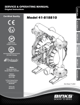
Legend
1—Supply
2—Control
3—Delivery
Ex-Exhaust
Fig. 2 Outline View
4 17/32”
3 25/32”
7 ¼”

Page 3
REPAIR PARTS LIST
Old Part Number New Part
Number
Ref.
No.
-538975-00000
-850012-00000
R431000091
R431000110
C-2 RELAY VALVE, complete
RELAY VALVE PORTION complete
(Includes Ref. Nos. 2 to 42, inclusive)
P –050756-00001
-850050-00000
R431002759
R431000127
2 BODY, Relay Valve
VALVE, Supply complete (Includes
3,5,9,10 and R431000128)
-850015-00000 R431000113 3 CAGE, Supply Valve
SEE KIT SEE KIT 4* RING, 1-7/16” O.D. Supply Valve
Cage Packing
SEE KIT SEE KIT 5* SPRING, Supply Valve
SEAL, Supply Valve, complete
(Includes 6,7, and 8)
-850046-00000 R431000126 6 HOUSING, Supply Valve Seal
SEE KIT SEE KIT 7* SEAL, Supply Valve
-850019-00000 R431000114 8 RETAINER, Supply Valve Seal
SEE KIT SEE KIT 9* RING, 5/8” O.D. Supply V. Seal
P –049882-00010 R431002387 10 RING, Supply Valve Retaining
P –049882-00044 R431002397 11 RING, Supply Valve Cage Retaining
-850022-00000 R431000116 20 STEM, Diaphragm
-521391-00000
-850023-00000
R431000021
R431000117
21* SPRING, Diaphragm Stem
VALVE, Exhaust, complete (Includes
22,26,27,29, and R431000119)
-850024-00000
-850025-00000
R431000118
R431000119
22 CAGE, Exhaust Valve
SEAL, Exhaust Valve, complete
(Includes 23, 24, and 25)
-850026-00000 R431000120 23 HOUSING, Exhaust Valve Seal
SEE KIT SEE KIT 24* SEAL, Exhaust Valve
850028 R431000121 25 RETAINER, Exhaust Valve Seal
SEE KIT SEE KIT 26* RING, 15/16” O.D. Ex.V. Seal
Housing Packing
SEE KIT SEE KIT 27* SPRING, Exhaust Valve
SEE KIT SEE KIT 28* RING, 1-5/8” O.D. Cage Packing
P –049921-00003 R431002551 29 RING, Exhaust Valve Retaining
P –049882-00010
-850030-00000
R431002387
R431000122
30 RING, Exhaust Valve Cage
DIAPHRAGM complete (Includes
35, 36, 37, three of 38 and 39)
-850031-00000 R431000123 35 FOLLOWER, Diaphragm
SEE KIT SEE KIT 36* DIAPHRAGM
P –067541-00000 R431007214 37 PLATE, Diaphragm Clamping
P –051181-00000 R431002887 38 SCREW, Diaphragm Clamping
(3 req’d)
P –049976-00004 R431002567 39 NUT, Diaphragm Clamping
(3 req’d)
SEE KIT SEE KIT 40*
GASKET, 9/16” Port
P –050394-00001 R431002633 41 COVER, Diaphragm
P –049871-00004 R431002350 42 BOLT, 5/16” x 1-1/4”
Diaphragm Cover (6 req’d)
P –049901-00020 R431002419 43 NUT, 5/16” x 1-1/4”
-527583-00000 R431000048 47 STRAINER (2 req’d)
-529161-00000 R431000051 48 RING, Strainer Retaining (2 req’d)
SEE KIT SEE KIT 49* GASKET, Pipe Bracket
P –050395-00000 R431002634 50 BRACKET, Pipe
P –049832-00149 R431002242 51 BOLT, 3/8” x 1-7/8”
Pipe Bracket (3 req’d)
P –049832-00149 R431002242 52 BOLT, 3/8” x 2-1/4” Pipe Bracket
P –049876-00001 R431002357 53 NUT, 3/8” (2 req’d)
Pipe Bracket (3 req’d)
*NOTE: Parts marked with an asterisk are recommended spares to be carried in stock at all times, Suggested quantities are 100% for rubber parts and 25%
for all other parts recommended. Spare parts may be ordered in Kit Form Pg. No R431004938 (Old No. P –059191-00000)
Prices will be quoted upon application
Orders should give PART NUMBER and NAME of part wanted
Fig. 3. Assembly View
A

Page 4
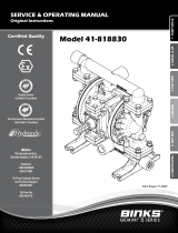
Referring to Figure 4, with supply air
pressure present in port 1 and no air pressure
present on the control diaphragm 36, both the
supply valve 7 and the exhaust valve 24 will be
seated by their respective springs. Assume that
air pressure is admitted to the control port 2 of
the valve. This pressure will be delivered to the
upper side of diaphragm 36 causing it to move
downward, carrying diaphragm stem 20 with it.
During this movement, the diaphragm stem will
contact the differential type supply valve 7 and
unseat it by compression of spring 5. Supply air
from port 1 will then flow past the unseated
valve to the delivery port 3 where it is piped to
the device being operated. Supply air also flows
through the choke in the exhaust valve cage 22
to the underside of the control diaphragm 36.
When the pressure under the diaphragm is
substantially equal to the control pressure on top
of the diaphragm, the diaphragm assembly will
move back toward its initial position and the
supply valve will seal, aided by spring 5, thus
cutting off further flow of supply air to the
delivery port.
The relay valve will maintain this delivery
pressure against leakage. In the case of a
reduction in delivery pressure, the higher
pressure on the upper side of the diaphragm will
cause movement downward repeating the
application cycle and restoring the delivery
pressure to the desired value.
When the control pressure to the valve is
reduced, the higher pressure on the
underside of the diaphragm 36 will cause it to
move upward carrying stem 20 with it. During
this movement, a shoulder on the diaphragm
stem will contact the differential type exhaust
valve 24 and unseat it by compression of
spring 27. Air from the delivery port will then
flow past the unseated exhaust valve to
atmosphere reducing the pressure in the
device being operated. When this pressure
has been reduced to balance the pressures
on diaphragm 36, the diaphragm assembly
will move back toward its initial position and
the exhaust valve will seal aided by spring 27,
thus cutting off the flow of air to exhaust. If the
control pressure is completely removed from
the diaphragm, the valve will completely
e x h a u s t t h e d e l i v e r y p r e s s u r e .
During an application of air to an
operating device, if the pressure in the
delivery line should increase due to
temperature variation or other causes, this
condition will unbalance the diaphragm to
repeat the exhaust cycle described above
until the desired pressure is again reached.
From the foregoing it will be seen that the
C-2 Relay Valve will reproduce in the delivery
line a pressure equal to that in the control line
and will maintain this pressure against
leakage or temperature effect.
Fig. 4. Diagrammatic View
22
36
27
24
20
7
5
CONTROL———-2
EXHAUST ———EX
DELIVERY ———3
SUPPLY ——–—-1

Page 5
NOTICE TO PRODUCT USERS
1. WARNING: FLUID MEDIA
AVENTICS pneumatic devices are designed and tested for use
with filtered, clean, dry, chemical free air at pressures and
temperatures within the specified limits of the device. For use
with media other than air or for human life support systems,
AVENTICS must be consulted. Hydraulic cylinders are designed
for operation with filtered, clean, petroleum based hydraulic fluid;
operation using fire-resistant or other special types of fluids may
require special packing and seals. Consult the factory.
2. WARNING: MATERIAL COMPATIBILITY
Damage to product seals or other parts caused by the use of
noncompatible lubricants, oil additives or synthetic lubricants in
the air system compressor or line lubrication devices voids
AVENTICS warranty and can result in product failure or other
malfunction. See lubrication recommendations below.
AIR LINE LUBRICANTS! In service higher than 18 cycles per
minute or with continuous flow of air through the device, an air
line lubricator is recommended.* (Do not use line lubrication with
vacuum products.) However, the lubricator must be maintained
since the oil will wash out the grease, and lack of lubrication will
greatly shorten the life expectancy. The oils used in the
lubricator must be compatible with the elastomers in the device.
The elastomers are normally BUNA-N, NEOPRENE, VITON,
SILICONE and HYTREL. AVENTICS recommends the use of
only petroleum based oils without synthetic additives, and with
an aniline point between 180° F and 210° F.
COMPRESSOR LUBRICANTS! All compressors (with the
exception of special "oil free" units) pass oil mist or vapor from
the internal crankcase lubricating system through to the
compressed air. Since even small amounts of non-compatible
lubricants can cause severe seal deterioration (which could
result in component and system failure) special care should be
taken in selecting compatible compressor lubricants.
3. WARNING: INSTALLATION AND MOUNTING
The user of these devices must conform to all applicable
electrical, mechanical, piping and other codes in the installation,
operation or repair of these devices.
INSTALLATION ! Do not attempt to install, operate or repair
these devices without proper training in the technique of working
on pneumatic or hydraulic systems and devices, unless under
trained supervision. Compressed air and hydraulic systems
contain high levels of stored energy. Do not attempt to connect,
disconnect or repair these products when a system is under
pressure. Always exhaust or drain the pressure from a system
before performing any service work. Failure to do so can result
in serious personal injury.
MOUNTING! Devices should be mounted and positioned in such
a manner that they cannot be accidentally operated.
4. WARNING: APPLICATION AND USE OF PRODUCTS
The possibility does exist for any device or accessory to fail to
operate properly through misuse, wear or malfunction. The user
must consider these possibilities and should provide appropriate
safe guards in the application or system design to prevent
personal injury or property damage in the event of a malfunction.
5. WARNING: CONVERSION, MAINTENANCE AND REPAIR
When a device is disassembled for conversion to a different
configuration, maintenance or repair, the device must be tested
for leakage and proper operation after being reassembled and
prior to installation.
MAINTENANCE AND REPAIR! Maintenance periods should be
scheduled in accordance with frequency of use and working
conditions. All AVENTICS products should provide a minimum of
1,000,000 cycles of maintenance free service when used and
lubricated as recommended. However, these products should be
visually inspected for defects and given an "in system" operating
performance and leakage test once a year. Where devices
require a major repair as a result of the one million cycles, one
year, or routine inspection, the device must be disassembled,
cleaned, inspected, parts replaced as required, rebuilt and
tested for leakage and proper operation prior to installation. See
individual catalogs for specific cycle life estimates.
6. PRODUCT CHANGES
Product changes including specifications, features, designs and
availability are subject to change at any time without notice. For
critical dimensions or specifications, contact factory.
*Many AVENTICS pneumatic valves and cylinders can operate
with or without air line lubrication; see individual sales catalogs
for details.
LIMITATIONS OF WARRANTIES & REMEDIES
AVENTICS warrants its products sold by it to be free from defects in material and workmanship to the following:
For twelve months after shipment AVENTICS will repair or replace (F.O.B. our works), at its option, any equipment which under normal
conditions of use and service proves to be defective in material or workmanship at no charge to the purchaser. No charge will be made for labor
with respect to defects covered by this Warranty, provided that the work is done by AVENTICS or any of its authorized service facilities.
However, this Warranty does not cover expenses incurred in the removal and reinstallation of any product, nor any downtime incurred, whether
or not proved defective.
All repairs and replacement parts provided under this Warranty policy will assume the identity, for warranty purposes, of the part replaced, and
the warranty on such replacement parts will expire when the warranty on the original part would have expired. Claims must be submitted within
thirty days of the failure or be subject to rejection.
This Warranty is not transferable beyond the first using purchaser. Specifically, excluded from this Warranty are failures caused by misuse,
neglect, abuse, improper operation or filtration, extreme temperatures, or unauthorized service or parts. This Warranty also excludes the use of
lubricants, fluids or air line additives that are not compatible with seals or diaphragms used in the products. This Warranty sets out the
purchaser's exclusive remedies with respect to products covered by it, whether for negligence or otherwise. Neither, AVENTICS nor any of its
affiliates will be liable for consequential or incidental damages or other losses or expenses incurred by reason of the use or sale of such products.
Our liability (except as to title) arising out of the sale, use or operation of any product or parts, whether on warranty, contract or negligence
(including claims for consequential or incidental damage) shall not in any event exceed the cost of replacing the defective products and, upon
expiration of the warranted period as herein provided, all such liability is terminated. THIS WARRANTY IS IN LIEU OF ALL OTHER
WARRANTIES, EXPRESS OR IMPLIED, WHETHER FOR MERCHANTABILITY OR FITNESS FOR A PARTICULAR PURPOSE OR OTHERWISE.
No attempt to alter, amend or extend this Warranty shall be effective unless authorized in writing by an officer of AVENTICS Corporation.
AVENTICS reserves the right to discontinue manufacture of any product, or change product materials, design or specifications without
notice.

m
AVENTICS
/