Page is loading ...

Changing the Setpoint/Modify Key: Press and
hold to view current setpoint temperature. While
held, press the decrease or increase key to change the
setpoint.
Decrease Key: Press in conjunction with Modify
Key in order to decrease setpoint.
Increase Key: Press in conjunction with Modify
Key in order to increase setpoint.
Changing the Controller Parameters
The BB703 operates at its optimum performance when
left with the factory parameter settings. The only
internal parameter that the operator may need to change
is the engineering units (°C or °F) or display resolution
(XXX, XXX.X or X.XX).
ARTWORK/PRODUCT ART/
DWGS/START HERE ARROW
5
ARTWORK/PRODUCT ART/
DWGS/START HERE ARROW
6
BB703
Blackbody Calibrator
Menu 1 Menu 2 Menu 3
TUNE OFF SP1.P 0 SP1.d SSd1
BAND A 58 hAnd OFF SP2.d SSd2
int.t A 1.2 PL.1 100 burn uP.SC
der.t A 8 PL.2 100 rEU.d 1r.2d
daC A 2.0 sp2.A none rEU.L 1n.2n
CyC.t A 5 sp2.b none SPAn * 10
oFSt 0.0 diSp 0.1º Zero * -2.5
SP.LK OFF hi.SC 752 ChEK OFF
SP.rr 0 Lo.SC 32 rEAd Uarº
SPrn OFF ipPt rtd tECh Ct A
SOAK - - unit ºF Uer 392
SEt.2 0.0 rSEt nonE
bnd.2 3.6
CyC.2 on.oF
Menu Hierarchy Showing Factory
Default Settings
1. To enter programming
menu hold down the
and
keys, simultaneously, for 3 seconds. Upon entering the menu,
the user is always located at the “tUnE” parameter. This is the
first parameter of MENU1.
2. Use the
and
keys to scan through the various
parameters on a given menu level.
3. Use the
key together with the
key or the
key to
change a given parameter.
4. To change menu levels, scan to the first parameter on a given menu
level, using the
key. Next, hold down the key in addition
to the
key or the key to go to a different menu level.
5. To leave the programming menu and return to the normal
operation mode, hold down the
and keys, simultaneously.
6. All parameters are saved, even when power is removed from the
unit.
Overheat Reset Switch
If the unit is operated at high temperatures in elevated
ambient temperatures, an overheat condition may occur.
In an overheat situation a mechanical reset switch on
the right side panel will pop and open the heater circuit.
The controller will still have power. While the controller
will be demanding heat from the heater, the process
temperature will fall continuously until it equalizes with
the room temperature. If an overheat condition occurs,
let the unit cool off for one hour (leave the unit on),
then press the reset button, firmly.
Overheat Reset Switch (Right Side Panel)
SECTION 4: RS232 Communications
This section only applies to BB703 Series Calibrators pur-
chased with optional RS-232 Communications
(-C2) Option.
Communication Port
The RS-232 communication port is located on the left
side of the BB703 calibrator. An interface cable, Pt. No.
OM-NOMAD-CP9, is included with your unit for easy
connection between your BB703 calibrator and PC.
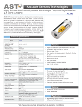
Wiring Connections From Calibrator To PC
CN9-SW Communication Software
Calibrators with the –C2 option come complete with
communication software (CN9-SW). The software is
designed to interface with your calibrator. Refer to
the Software Communication Manual (M2896) for
factory default settings and for making changes to the
communications settings and programming.
OVERHEAT
RESET SWITCH
HANDLE
(IN RETRACT POSITION)
FRONT
BACK
FAN
NOTE:
16151413131110
9
8765432
1
BENCHTOP CONTROLLER
INTERNAL WIRING
STEREO JACK
SIDE PANEL
1.8 m (6 ft.)
PC COM PORT
DB–9
15
STEREO PLUG –– DB–9
INTERFACE CABLE
CONTROLLER
TX
TX
RX
GND
RX
GRN
omega.com info@omega.com
TM
The information contained in this document is believed to be correct, but
OMEGA accepts no liability for any errors it contains, and reserves the right to
alter specifications without notice.
Servicing North America:
U.S.A. Omega Engineering, Inc.
Headquarters: Toll-Free: 1-800-826-6342 (USA & Canada only)
Customer Service: 1-800-622-2378 (USA & Canada only)
Engineering Service: 1-800-872-9436 (USA & Canada only)
Tel: (203) 359-1660 Fax: (203) 359-7700
e-mail: info@omega.com
For Other Locations Visit omega.com/worldwide
WARRANTY/DISCLAIMER
OMEGA ENGINEERING, INC. warrants this unit to be free of defects
in materials and workmanship for a period of 37 months from
date of purchase. OMEGA’s WARRANTY adds an additional one
(1) month grace period to the normal three (3) year product
warranty to cover handling and shipping time. This ensures that
OMEGA’s customers receive maximum coverage on each product.
If the unit malfunctions, it must be returned to the factory for
evaluation. OMEGA’s Customer Service Department will issue an
Authorized Return (AR) number immediately upon phone or written
request. Upon examination by OMEGA, if the unit is found to be
defective, it will be repaired or replaced at no charge. OMEGA’s
WARRANTY does not apply to defects resulting from any action of
the purchaser, including but not limited to mishandling, improper
interfacing, operation outside of design limits, improper repair,
or unauthorized modification. This WARRANTY is VOID if the unit
shows evidence of having been tampered with or shows evidence of
having been damaged as a result of excessive corrosion; or current,
heat, moisture or vibration; improper specification; misapplication;
misuse or other operating conditions outside of OMEGA’s control.
Components in which wear is not warranted, include but are not
limited to contact points, fuses, and triacs.
OMEGA is pleased to offer suggestions on the use of its various
products. However, OMEGA neither assumes responsibility for
any omissions or errors nor assumes liability for any damages
that result from the use if its products in accordance with
information provided by OMEGA, either verbal or written.
OMEGA warrants only that the parts manufactured by the
company will be as specified and free of defects. OMEGA
MAKES NO OTHER WARRANTIES OR REPRESENTATIONS OF
ANY KIND WHATSOEVER, EXPRESSED OR IMPLIED, EXCEPT
THAT OF TITLE, AND ALL IMPLIED WARRANTIES INCLUDING
ANY WARRANTY OF MERCHANTABILITY AND FITNESS
FOR A PARTICULAR PURPOSE ARE HEREBY DISCLAIMED.
LIMITATION OF LIABILITY: The remedies of purchaser set forth
herein are exclusive, and the total liability of OMEGA with
respect to this order, whether based on contract, warranty,
negligence, indemnification, strict liability or otherwise,
shall not exceed the purchase price of the component upon
which liability is based. In no event shall OMEGA be liable for
consequential, incidental or special damages.
CONDITIONS: Equipment sold by OMEGA is not intended to be used,
nor shall it be used: (1) as a “Basic Component” under 10 CFR 21 (NRC),
used in or with any nuclear installation or activity; or (2) in medical
applications or used on humans. Should any Product(s) be used in or
with any nuclear installation or activity, medical application, used on
humans, or misused in any way, OMEGA assumes no responsibility
as set forth in our basic WARRANTY/DISCLAIMER language, and,
additionally, purchaser will indemnify OMEGA and hold OMEGA
harmless from any liability or damage whatsoever arising out of the use
of the Product(s) in such a manner.
RETURN REQUESTS/INQUIRIES
Direct all warranty and repair requests/inquiries to the OMEGA
Customer Service Department. BEFORE RETURNING ANY
PRODUCT(S) TO OMEGA, PURCHASER MUST OBTAIN AN
AUTHORIZED RETURN (AR) NUMBER FROM OMEGA’S CUSTOMER
SERVICE DEPARTMENT (IN ORDER TO AVOID PROCESSING
DELAYS). The assigned AR number should then be marked on the
outside of the return package and on any correspondence.
FOR WARRANTY RETURNS,
please have the following
information available BEFORE
contacting OMEGA:
1. Purchase Order number
under which the product
was PURCHASED,
2. Model and serial number of the
product under warranty, and
3. Repair instructions and/or
specific problems relative
to the product.
FOR NON-WARRANTY REPAIRS,
consult OMEGA for current repair
charges. Have the following
information available BEFORE
contacting OMEGA:
1. Purchase Order number to cover
the COST of the repair or
calibration,
2. Model and serial number of the
product, and
3. Repair instructions and/or specific
problems relative to the product.
OMEGA’s policy is to make running changes, not model changes,
whenever an improvement is possible. This affords our customers
the latest in technology and engineering.
OMEGA is a trademark of OMEGA ENGINEERING, INC.
© Copyright 2017 OMEGA ENGINEERING, INC. All rights reserved.
This document may not be copied, photocopied, reproduced,
translated, or reduced to any electronic medium or machine-readable
form, in whole or in part, without the prior written consent of OMEGA
ENGINEERING, INC.
MQS3265/0118
For complete product manual:
www.omega.com/Manuals/manualpdf/M3265.pdf

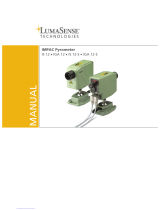
Front/Back Panel Controls and Indicators
Process Temperature/Setpoint Temperature Display
In the default mode, the display will show the process
temperature, i.e. the target plate temperature. When
the modify key is held down, the setpoint temperature
is displayed.
P.I.D. Indicator:
When this light is illuminated, the unit is heating up
the target plate.
Fuses
Refer to User’s Guide Section 5.3 for information on
fuse replacement.
Power Switch
The power switch has two positions, “ON” and
“STANDBY”.
ON STANDBY
In the ON mode, the entire unit is powered up. The fan
will only activate when the target plate is been brought
up to a high temperature for a period of about five
minutes.
ARTWORK/PRODUCT ART/
DWGS/START HERE ARROW
START HERE
ARTWORK/PRODUCT ART/
DWGS/START HERE ARROW
2
ARTWORK/PRODUCT ART/
DWGS/START HERE ARROW
3
ARTWORK/PRODUCT ART/
DWGS/START HERE ARROW
4
Using This Quick Start Manual
Use this Quick Start Manual with your BB703
Blackbody Calibrator for quick installation and
operation. For detailed information, refer to the
User’s Guide (Manual Number M3265).
SECTION 1 .........................General Information
SECTION 2 ....................................... Installation
SECTION 3 ........................................ Operation
SECTION 4 ......................RS232 Communication
PRECAUTIONS:
• Follow all safety precautions and operating
instructions outlined in this manual.
• Never leave your calibrator unattended when in
use.
• Keep out of reach of all children.
• Nothing should come in contact with the target
plate. Even when the unit is off.
• Never place any object within 3 inches of the
cavity opening when hot.
• Do not operate in flammable or explosive envi-
ronments.
• Never operate with a power cord other than the
one provided with your unit.
• Remove and or disconnect main power cord
before attempting any maintenance or fuse
replacement.
• Do not connect this unit to a non-grounded, non-
polarized outlet or power source.
• This unit is intended for indoor use only. Avoid
exposure to moisture.
There are no user serviceable parts inside your unit.
Attempting to repair or service your unit may void
your warranty.
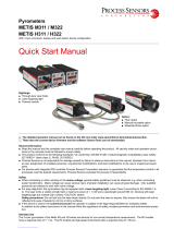
SECTION 1: General Information
The Model BB703 is a portable, rugged, bench-top,
hot blackbody calibration source with a built-in
precision PID digital controller. The calibrator is
used to test and calibrate infrared pyrometers.
The 28.6mm (1.125”) diameter target plate has an
emissivity of .95 and can be set to any temperature
between ambient +11 to 400°C (ambient +20 to
752°F).
BLACK POINT
Blackbody
TM
BB703
®
P. I. D. INDICATOR PROCESS TEMP./
SETPOINT TEMP.
DISPLAY
TARGET
PLATE
MODIFY
KEY
DECREASE
KEY
INCREASE
KEY
VENT
FAN EXHAUST POWER CORD SOCKET
FUSES POWER
SWITCH
In the STANDBY mode, the unit is powered down
except for the fan and fan thermostat. If the unit has
been operated at high temperature and is then put into
standby mode, the fan will still run until the target
plate has cooled down to room temperature.
SECTION 2: Installation
Power Connection
Connect the power cord to the AC Power Input. If you
have an International (230 VAC~, 50/60 Hz) model
you must first connect the international style power
cord to the proper connector used in your country or
local area (connector not provided).
Electrical connections and wiring should be performed
only by suitably trained personnel.
Be sure that the line voltage powering your unit does
not go above or below 10% of the rated voltages
specified above.
Mounting
Mount the unit on a bench, table top or shelf in a
horizontal position and operate at least ten inches
from any air obstructions to the front panel, rear panel,
side or top of the unit. Operate the unit in an ambient
environment between the specified 0 to 40°C (32 to
104°F).
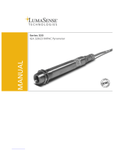
Ambient Temperature
When operating the unit at ambient temperatures
higher than 25°C (77°F), the user must not exceed the
“Maximum Allowable Target Plate Temperature”
shown along the y-axis in the following graph. Failure
to adhere to these guidelines may cause a safety switch
inside the unit to open the heater circuit. If the PID
light is blinking or continuously on but there is no
increase in target plate temperature, then the thermal
safety switch has tripped. In this case refer to SECTION
3 - Overheat Reset Switch or Section 3.3 in the User’s
Guide.
23.9 26.7 29.4 32.2 35.0 37.8 40.6
750
730
710
690
670
650
630
610
590
570
550
398.8
387.8
376.7
365.6
354.4
343.3
332.2
321.1
310.0
298.9
287.8
AMBIENT TEMPERATURE (C)
MAXIMUM ALLOWABLE
TARGET PLATE TEMPERATURE (F)
MAXIMUM ALLOWABLE
TARGET PLATE TEMPERATURE (C)
AMBIENT TEMPERATURE (F)
75
76.4
8580 90 95 100 105
OPERATING
REGION
104.0
24.7 40.0
Maximum Setpoint Temperature for Elevated
Ambient Temperatures
SECTION 3: Operation
Calibrating an IR Pyrometer
In order to calibrate an IR Pyrometer, hold the
pyrometer perpendicular to the target plate for
optimal performance. The proper distance between
the IR pyrometer and the target plate depends on
the field of view of the pyrometer. If the pyrometer
is too far away it will scan unwanted surfaces out-
side of the perimeter of the target plate. Holding
the pyrometer too close could introduce undesir-
able heat to the IR detector of the pyrometer.
---------------------------------------------------------------------------
Target Plate Emissivity: 0.95*
---------------------------------------------------------------------------
*Reference to 8-14 microns wavelength bandwidth
The BB703’s target plate can be set to very high
temperatures. Exercise extreme caution when
operating the unit. Keep hands and fingers away
from the target plate area. Keep flammable
products such as paper, plastics and clothing far
from the BB703.
WARNING:
NOTE:
CAUTION:
1/2