Page is loading ...

1404 327539-000
RESIDENTIAL GAS WATER HEATERS
Installation and Operating Manual
KEEP THIS MANUAL IN THE POCKET ON HEATER FOR FUTURE REFERENCE
WHENEVER MAINTENANCE ADJUSTMENT OR SERVICE IS REQUIRED.
DIRECT VENTED GAS MODELS
NOT FOR USE IN MANUFACTURED (MOBILE) HOMES
• For Your Safety •
AN ODOURANT IS ADDED TO THE GAS USED
BY THIS WATER HEATER.
ALL TECHNICAL AND WARRANTY QUESTIONS: SHOULD BE DIRECTED TO THE LOCAL DEALER FROM WHOM THE WATER HEATER WAS
PURCHASED. IF YOU ARE UNSUCCESSFUL, PLEASE CONTACT THE COMPANY LISTED ON THE RATING PLATE ON THE WATER HEATER.
www.gsw-wh.com

2 www. gsw-wh .com
TABLE OF CONTENTS
SAFE INSTALLATION, USE AND SERVICE . . . . . . . . . . .3
GENERAL SAFETY . . . . . . . . . . . . . . . . . . . . . . . . . . . . . .4
INTRODUCTION . . . . . . . . . . . . . . . . . . . . . . . . . . . . . . . .6
Qualifi ed Installer Or Service Agency . . . . . . . . . . . . 6
Preparing For The Installation. . . . . . . . . . . . . . . . . . 6
TYPICAL INSTALLATION. . . . . . . . . . . . . . . . . . . . . . . . . .7
Get To Know Your Water Heater - Gas Models
(List Referencing Figures 1-5). . . . . . . . . . . . . . . . . . 7
Replacement Parts And Deliming Products . . . . . . . 8
Combo Heating Inlet And Outlet Side Taps. . . . . . . . 8
High Limit Controls (Energy Cut Off). . . . . . . . . . . . . 8
Thermostat/Water Temperature
LOCATING THE NEW WATER HEATER. . . . . . . . . . . . . .9
Facts To Consider About The Location . . . . . . . . . . . 9
External/Internal Damage . . . . . . . . . . . . . . . . . . . . . 9
Air Requirements . . . . . . . . . . . . . . . . . . . . . . . . . . 10
Confi ned Space Installations. . . . . . . . . . . . . . . . . . 10
Clearances To Combustibles
Floors With Carpeting
Clearance For Servicing
Chemical Vapour Corrosion . . . . . . . . . . . . . . . . . . 10
Storage Of Flammable Liquids . . . . . . . . . . . . . . . . .11
Insulation Blankets . . . . . . . . . . . . . . . . . . . . . . . . . .11
Water Piping . . . . . . . . . . . . . . . . . . . . . . . . . . . . . . 12
Water Pressure
Mixing Valves
INSTALLING THE NEW WATER HEATER . . . . . . . . . . . 13
Water Piping Installation . . . . . . . . . . . . . . . . . . . . . 13
Closed Water Systems . . . . . . . . . . . . . . . . . . . . . . 13
Thermal Expansion . . . . . . . . . . . . . . . . . . . . . . . . . 13
Temperature-Pressure Relief Valve. . . . . . . . . . . . . 14
T&P Valve Discharge Pipe Requirements:
Temperature-Pressure Relief Valve And
Pipe Insulation
Filling The Water Heater . . . . . . . . . . . . . . . . . . . . . 15
Space Heating And Potable Water Systems. . . . . . 16
Combo Heating . . . . . . . . . . . . . . . . . . . . . . . . . . . . 17
System Requirements
Installation
Gas Piping. . . . . . . . . . . . . . . . . . . . . . . . . . . . . . . . 18
Sediment Trap. . . . . . . . . . . . . . . . . . . . . . . . . . . . . 19
High Altitude Installations . . . . . . . . . . . . . . . . . . . . 19
Venting . . . . . . . . . . . . . . . . . . . . . . . . . . . . . . . . . . 20
Vent Terminal Clearances . . . . . . . . . . . . . . . . . . . . 20
DV Termination Safety Cover . . . . . . . . . . . . . . . . . 21
Vent Connections . . . . . . . . . . . . . . . . . . . . . . . . . . 21
Locating Clearance Hole For Vent . . . . . . . . . . . . . 21
Standard Vent Arrangement . . . . . . . . . . . . . . . . . . 21
Vent Assembly. . . . . . . . . . . . . . . . . . . . . . . . . . . . . 22
Securing Vent Termination Assembly To
The Exterior Wall. . . . . . . . . . . . . . . . . . . . . . . . . . . 22
Vent Restricter Plate . . . . . . . . . . . . . . . . . . . . . . . . 22
Uncompressing The Corrugated Tubing . . . . . . . . . 22
Vent Connection To The Water Heater . . . . . . . . . . 23
Offset Vent Arrangement. . . . . . . . . . . . . . . . . . . . . 23
Installation Checklist . . . . . . . . . . . . . . . . . . . . . . . . 25
LIGHTING INSTRUCTIONS. . . . . . . . . . . . . . . . . . . . . . .26
TEMPERATURE REGULATION . . . . . . . . . . . . . . . . . . .27
Temperature Regulation . . . . . . . . . . . . . . . . . . . . . 27
Temperature Adjustment
Operating The Temperature Control System. . . . . . 27
Water Temperature Adjustment
Operating Modes And Settings
FOR YOUR INFORMATION. . . . . . . . . . . . . . . . . . . . . . . 28
External Damage . . . . . . . . . . . . . . . . . . . . . . . . . . 28
Start Up Conditions . . . . . . . . . . . . . . . . . . . . . . . . . 28
Condensate
Smoke/Odour
Thermal Expansion . . . . . . . . . . . . . . . . . . . . . . . . . 28
Strange Sounds . . . . . . . . . . . . . . . . . . . . . . . . . . . 29
Operational Conditions . . . . . . . . . . . . . . . . . . . . . . 29
Smelly Water
“Air” In Hot Water Faucets
High Water Temperature Shut Off System
MAINTENANCE . . . . . . . . . . . . . . . . . . . . . . . . . . . . . . . .30
Housekeeping . . . . . . . . . . . . . . . . . . . . . . . . . . . . . 30
Flood Damage. . . . . . . . . . . . . . . . . . . . . . . . . . . . . 30
Venting System Inspection . . . . . . . . . . . . . . . . . . . 30
Pilot And Main Burner . . . . . . . . . . . . . . . . . . . . . . . 30
Burner Flames. . . . . . . . . . . . . . . . . . . . . . . . . . . . . 31
Servicing The Water Heater . . . . . . . . . . . . . . . . . . 31
Removing And Replacing The Gas Control Valve/
Thermostat . . . . . . . . . . . . . . . . . . . . . . . . . . . . . . . 31
Removing The Gas Control Valve/Thermostat:
Replacing The Gas Control Valve/Thermostat:
Removing The Manifold/Burner Assembly . . . . . . . 31
Removing The Burner From The Manifold/Burner
Assembly. . . . . . . . . . . . . . . . . . . . . . . . . . . . . . . . . 32
Natural Gas (Low Nox) & Propane (LP) Gas Burner
Replacing The Pilot/Thermopile Assembly . . . . . . . 32
Replacing The Manifold/Burner Assembly . . . . . . . 33
Piezoelectric Igniter System . . . . . . . . . . . . . . . . . . 34
Testing The Igniter System . . . . . . . . . . . . . . . . . . . 34
Temperature-Pressure Relief Valve Test. . . . . . . . . 34
Draining, Refi lling And Flushing . . . . . . . . . . . . . . . 34
To Drain The Water Heater Storage Tank
To Refi ll The Water Heater Storage Tank
To Flush The Water Heater Storage Tank
Drain Valve Washer Replacement . . . . . . . . . . . . . 35
Anode Rod Maintenance. . . . . . . . . . . . . . . . . . . . . 35
To Remove The Anode Rod:
To Install The Anode Rod:
LEAKAGE CHECKPOINTS . . . . . . . . . . . . . . . . . . . . . . .37
Service . . . . . . . . . . . . . . . . . . . . . . . . . . . . . . . . . . 37
REFERENCE PARTS LISTING . . . . . . . . . . . . . . . . . . . .38
TROUBLESHOOTING GUIDELINES. . . . . . . . . . . . . . . .40
NOTES . . . . . . . . . . . . . . . . . . . . . . . . . . . . . . . . . . . . . . .44

www. gsw-wh .com 3
SAFE INSTALLATION, USE AND SERVICE
Your safety and the safety of others is extremely important in the installation, use and servicing of this water heater.
Many safety-related messages and instructions have been provided in this manual and on your own water heater to warn you
and others of a potential injury hazard. Read and obey all safety messages and instructions throughout this manual. It is very
important that the meaning of each safety message is understood by you and others who install, use or service this water heater.
This is the safety alert symbol. It is used to alert you
to potential personal injury hazards. Obey all safety
messages that follow this symbol to avoid possible
injury or death.
CAUTION used without the safety alert
symbol indicates a potentially hazardous
situation which, if not avoided, could
result in property damage
CAUTION indicates a potentially
hazardous situation which, if not avoided,
could result in minor or moderate injury.
WARNING indicates a potentially
hazardous situation which, if not avoided,
could result in death or injury.
DANGER indicates an imminently
hazardous situation which, if not avoided,
will result in death or injury.
CAUTION
WARNING
CAUTION
DANGER
All safety messages will generally tell you about the type of hazard, what can happen if you do not follow the safety message
and how to avoid the risk of injury.
IMPORTANT DEFINITIONS
Qualifi ed Installer: A qualifi ed installer must have ability equivalent to a licensed tradesman in the fi elds of plumbing,
air supply, venting and gas supply, including a thorough understanding of the requirements of the National Fuel Gas
Code as it relates to the installation of gas fi red water heaters. The qualifi ed installer must also be familiar with the
design features and use of fl ammable vapor ignition resistant water heaters and have a thorough understanding of this
Installation and Operating manual.
Service Agency: A service agency also must have ability equivalent to a licensed tradesman in the fi elds of plumbing, air
supply, venting and gas supply, including a thorough understanding of the requirements of the National Fuel Gas Code
as it relates to the installation of gas fi red water heaters. The service agency must also have a thorough understanding
of this Installation and Operating manual, and be able to perform repairs strictly in accordance with the service guidelines
provided by the manufacturer.
Gas Supplier: The Natural Gas or Propane Utility or service who supplies gas for utilization by the gas burning appliances
within this application. The gas supplier typically has responsibility for the inspection and code approval of gas piping
up to and including the Natural Gas meter or Propane storage tank of a building. Many gas suppliers also offer service
and inspection of appliances within the building.

4 www. gsw-wh .com
GENERAL SAFETY
Read instruction manual before
installing, using or servicing
water heater.
• Do not store or use gasoline or other flammable
vapours and liquids in the vicinity of this water
heater, the vent termination hood or any other
appliance.
• Avoid all ignition sources if you smell gas.
• Do not expose water heater control to excessive
gas pressure.
• Use only gas shown on rating plate.
• Maintain required clearances to combustibles.
• Keep ignition sources away from faucets after
extended period of non-use.
Fire or Explosion Hazard
WARNING

www. gsw-wh .com 5
GENERAL SAFETY
Installation: Do not install the water heater or the vent termina-
tion hood where flammable products will be stored or used.
Vapours from flammable
liquids may explode and
catch fire causing death or
severe burns.
Do not use or store
flammable products such as
gasoline, solvents or adhe-
sives in the same room or
area near the water heater or
the vent termination hood.
Keep flammable products:
1. far away from heater,
2. in approved containers,
3. tightly closed and
4. out of children's reach.
Water heater has a main
burner and pilot. While
operating, the pilot flame:
1. is in continuous operation
and
2. will ignite flammable
vapours.
Vapours:
1. cannot be seen,
2. are heavier than air,
3. go a long way on the floor
and
4. can be carried from other
rooms by air currents.
Flammable Vapours
FLAMMBLE
DANGER
Breathing carbon monoxide can cause brain damage or death.
Always read and understand instruction manual.
• Install vent system in accordance with codes.
• Do not operate water heater if flood damaged.
• For operation above 2347m (7,700’), a high
altitude orifice must be installed.
• Do not operate if soot buildup is present.
• Do not place chemical vapor emitting products
near water heater or vent termination hood.
• Gas and carbon monoxide detectors are
available.
Breathing Hazard - Carbon Monoxide Gas
WARNING

6 www. gsw-wh .com
INTRODUCTION
Thank You for purchasing this water heater. Properly
installed and maintained, it should give you years of trouble
free service.
This water heater is suitable for potable water heating
and space heating applications but not for space heating
only applications.
Abbreviations found in this Installation and Operating
manual:
• CSA - Canadian Standards Association
• ANSI - American National Standards Institute
• ASME - American Society of Mechanical Engineers
This gas-fi red water heater is design certifi ed by CSA
International, under Water Heater Standard ANSI
Z21.10.1 • CSA 4.1 (current edition).
QUALIFIED INSTALLER OR SERVICE AGENCY
Installation and service of this water heater requires ability
equivalent to that of a Qualifi ed Agency (as defi ned by
ANSI below) in the fi eld involved. Installation skills such
as plumbing, air supply, venting, gas supply and electrical
supply are required in addition to electrical testing skills
when performing service.
ANSI Z223.1 2006 Sec. 3.3.83: “Qualifi ed Agency” - “Any
individual, fi rm, corporation or company that either in
person or through a representative is engaged in and is
responsible for (a) the installation, testing or replacement
of gas piping or (b) the connection, installation, testing,
repair or servicing of appliances and equipment; that
is experienced in such work; that is familiar with all
precautions required and that has complied with all the
requirements of the authority having jurisdiction.”
If you are not qualifi ed (as defi ned by ANSI above) and
licensed or certified as required by authority having
jurisdiction to perform a given task, do not attempt to
perform any of the procedures described in this manual.
If you do not understand the instructions given in this
manual do not attempt to perform any procedures outlined
in this manual.
PREPARING FOR THE INSTALLATION
1. Read the “General Safety” section of this manual
fi rst and then entire manual carefully. If you don’t
follow safety rules, the water heater will not operate
properly. It could cause DEATH, SERIOUS BODILY
INJURY AND/OR PROPERTY DAMAGE. This manual
contains instructions for installation, operation,
and maintenance of the gas-fi red water heater. It
also contains warnings throughout the manual that
you must read and be aware of. All warnings and
instructions are essential to proper operation of the
water heater and your safety. Since we cannot put
everything on the fi rst few pages, READ ENTIRE
MANUAL BEFORE ATTEMPTING TO INSTALL OR
OPERATE THE WATER HEATER.
2. The installation must conform with these instructions
and local code authority having jurisdiction. In
absence of local codes, installation must comply with
current editions of the “Natural Gas and Propane
Installation Code” B149.1 and “Canadian Electrical
Code (C22.1), Part I” . All documents are available
from:
Canadian Standards Association,
5060 Spectrum Way,
Mississauga, Ontario, Canada
L4W 5N6
3. If after reading this manual you have any questions or
do not understand any portion of the instructions, call
the local gas utility or the manufacturer whose name
appears on the rating plate.
4. Carefully plan the place where you are going to put
the water heater. Correct combustion, vent action, and
vent pipe installation are very important in preventing
death from possible carbon monoxide poisoning and
fi res (see Figure 6). Examine the location to ensure
the water heater complies with the “Locating The New
Water Heater” section in this manual.
5. For installation in areas subject to earthquakes, this
water heater must be braced, anchored, or strapped to
avoid falling or moving during an earthquake. Contact
local utilities for code requirements in your area.
6. This product is certifi ed to comply with a maximum
weighted average of 0.25% lead content as required
in some areas.

www. gsw-wh .com 7
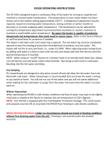
TYPICAL INSTALLATION
GET TO KNOW YOUR WATER HEATER - GAS MODELS (LIST REFERENCING FIGURES 1-5)
1 Vent Termination Hood
2 Wall Plate
3 ***Vent Pipe
4 Cold Water Inlet Nipple/Diptube
5 **Combo Heating System Supply
Outlet (Optional)
6 T&P Valve
7 Gas Control Valve/Thermostat
(Honeywell)
8 **Combo Heating System Return
Inlet (Optional)
9 *Discharge Pipe
10 Drain Valve
11 Outer Gas Door
12 Manifold Door Assembly (behind
outer door) (see Figure 3 &
Figure 4)
13 *Floor Drain
14 *Metal Drain Pan
15 Flexible Manifold Tube (see
Figure 3 & Figure 4)
16 *Sediment Trap
17 *Ground Joint Union (gas
connection)
18 *Main Manual Gas Shut-off Valve
19 *Gas Supply
20 Baffl e Assembly
21 Rating Plate
22 Anode (under cap)
23 Hot Water Outlet Nipple (or
Optional Nipple/Anode)
24 *Inlet Water Shut-off Valve
25 *Union (water connection)
26 Air Inlet Snorkel
27 Air Tower
28 ***Airbox
29 *Thermal Expansion Tank (required
for all closed systems)
30 Sheet Metal Burner (see Figure 3 &
Figure 4)
31 Gas Orifi ce (see Figure 3 &
Figure 4)
32 Gas Manifold (see Figure 3 &
Figure 4)
33 Manifold Door Gasket (see Figure 3
& Figure 4)
34 Manifold Door (see Figure 3 &
Figure 4)
35 Two Piece Grommet With Clip (see
Figure 3 & Figure 4)
36 Viewport (see Figure 3 & Figure 4)
37 Flexible Manifold Tube (see
Figure 3 & Figure 4)
38 Pilot (see Figure 3 & Figure 4)
39 Thermopile (see Figure 3 &
Figure 4)
40 Pilot Shield (see Figure 3 &
Figure 4)
*, **, *** see notes on following page
Front View
23
1 32
6
20
4
9
10
13
14
15
16
17
18
19
2
21
11 12
4
7
22
8
5
Figure 1
Rear View
24
29
25
25
26
1
27
28
Figure 2

8 www. gsw-wh .com
Natural gas and Propane (LP)
main burner with igniter assembly
for 38k to 42k Btu/hr models
31
36
38
39
30
33
34
35
32
37
40
Figure 3
37
Natural gas and Propane
(LP) main burner with igniter
assembly for 47k Btu/hr
models
35
36 34
33
32
31
4039
38 30
Figure 4
Vacuum relief valve
install per local
codes (not supplied
with heater).
Figure 5
Notes:
* Items not supplied with the water heater.
** The side recirculation loop connections may not be
used as the primary water inlet and outlet connections.
See “Combo Heating Inlet And Outlet Side Taps”
below.
*** During operation the vent pipe and airbox can get hot.
REPLACEMENT PARTS AND DELIMING PRODUCTS
Replacement parts and recommended delimer may be
ordered through authorized servicers or distributors. When
ordering parts, provide complete model and serial numbers
(see rating plate), quantity and name of part desired.
Standard hardware items may be purchased locally.
COMBO HEATING INLET AND OUTLET SIDE TAPS
Models equipped with Combo Heating capabilities are
shipped with the two side plumbing taps OPEN (items 5
and 8 in Figure 1 and see also Figure 8). If the heater is to
be operated without using the side taps, these openings
must be closed with the two pipe plugs supplied with
the heaters.
HIGH LIMIT CONTROLS (ENERGY CUT OFF)
Thermostat/Water Temperature
This feature is a part of the gas control valve/thermostat
(see Figure 1, item 7) and limits the maximum water
temperature. In the event of the water overheating, this
safety feature shuts off the fuel supply to the burner.

www. gsw-wh .com 9
LOCATING THE NEW WATER HEATER
FACTS TO CONSIDER ABOUT THE LOCATION
Carefully choose an indoor location for the new water
heater because the placement is a very important
consideration for the safety of the occupants in the building
and for the most economical use of the appliance. This
water heater is not for use in manufactured (mobile) homes
or outdoor installation.
Whether replacing an old water heater or putting the water
heater in a new location, the following critical points must
be observed:
1. Select a location indoors as close as practical to the
vent termination position. Figure 27 shows the venting
distances that the heater can be from the outside wall.
Ensure the vent termination position maintains the
clearances as outlined in Figure 27 thru Figure 29.
2. Selected location must provide adequate clearances
for servicing and proper operation of the water heater.
3. Avoid locations that could cause the water heater to
freeze from outside air.
4. Avoid locations that expose the water heater to direct
sunlight.
5. Keep combustibles such as boxes, magazines,
clothes, etc., away from the water heater area.
• All water heaters eventually leak.
• Do not install without adequate drainage.
Property Damage Hazard
CAUTION
Installation of the water heater must be accomplished
in such a manner that if the tank or any connections
should leak, the fl ow of water will not cause damage to
the structure. For this reason it is not advisable to install
the water heater in an attic or upper fl oor. In all cases, a
metal drain pan should be installed under the water heater.
Metal drain pans are available at your local hardware store.
Such a metal drain pan must have a clearance of at least
25mm (1”) greater than any point on the water heater’s
outer jacket and must be piped to an adequate drain. The
pan must have a maximum depth of 45mm (1.75”).
Water heater life depends upon water quality, water
pressure and the environment in which the water heater
is installed. Water heaters are sometimes installed in
locations where leakage may result in property damage,
even with the use of a metal drain pan piped to a drain.
However, unanticipated damage can be reduced or
prevented by a leak detector or water shut-off device used
in conjunction with a piped metal drain pan. These devices
are available from some plumbing supply wholesalers and
retailers, and detect and react to leakage in various ways:
• Sensors mounted in the metal drain pan that trigger an
alarm or turn off the incoming water to the water heater
when leakage is detected.
• Sensors mounted in the metal drain pan that turn off
the water supply to the entire building when water is
detected in the metal drain pan.
• Water supply shut-off devices that activate based on
the water pressure differential between the cold water
and hot water pipes connected to the water heater.
• Devices that will turn off the gas supply to a gas water
heater while at the same time shutting off its water
supply.
EXTERNAL/INTERNAL DAMAGE
Do not operate the water heater until it has been fully
checked out by a qualifi ed technician, if the water heater:
• Has been exposed to fi re or damage.
• Displays evidence of sooting.
• Produces steam or unusually hot water.
If the water heater has been fl ooded it must be replaced.

10 www. gsw-wh .com
AIR REQUIREMENTS
For safe operation an adequate supply of fresh,
uncontaminated air must be provided for combustion.
This gas-fi red water heater is a direct vent model. It
connects directly to the outside of the building through
the vent termination hood. The hood operates as both
the combustion air intake and the heater exhaust port
(see Figure 15).
All combustion air is obtained from outside the building
through this hood. Ensure the area around the termination
hood is always kept clear and that the air supply is not
exposed to contamination or fl ammable vapours.
CONFINED SPACE INSTALLATIONS
This water heater connects to the vent termination hood
using the sealed air intake and exhaust piping (see Figure
1 and Figure 2).
During operation this piping can become hot, especially in
areas experiencing high ambient temperatures.
When installed in a confi ned space such as a closet, it is
recommended that the confi ned space be ventilated to
minimize the buildup of heat around the heater. Figure 6
and Figure 7 show an examples of ventilating a confi ned
space.
0mm
(0”) MIN.
0mm
(0”) MIN. 0mm
(0”) MIN.
140mm
(5.5”) MIN.
TOP VIEW
OF CLOSET
WITHOUT DOOR
TOP VIEW OF
CLOSET WITH
DOOR
Figure 6
FRONT VIEW
OF DOOR
ROOM AIR
FLOW
ROOM AIR
FLOW
VENTILATION
AIR
OPENING
Figure 7
Clearances To Combustibles
Minimum clearances between water heater and
combustibles are 0mm (0”) at the sides and rear, 140mm
(5.5”) from the front and 305mm (12”) from top. Minimum
clearances from vent piping to combustibles is 25mm
(1”) except as noted in Figure 20. If clearances stated
on the heater differ from these clearances, install water
heater according to clearances stated on the heater (see
Figure 6).
Floors With Carpeting
This water heater must not be installed directly on
carpeting. Carpeting must be protected by a metal or wood
panel beneath the appliance extending beyond the full
width and depth of the appliance by at least 76mm (3”) in
every direction, or if the appliance is installed in an alcove
or closet, the entire fl oor must be covered by the panel.
Failure to heed this warning may result in a fi re hazard.
Clearance For Servicing
Adequate clearance of 610mm (24”) for servicing this
appliance should be considered before installation, such
as changing the anodes, etc.
A minimum clearance of 140mm (5.5”) must be allowed
for access to replaceable parts such as thermostats, drain
valve and relief valve.
When installing the heater, consideration must be given to
proper location. Location selected should be as close to
the wall as practicable and as centralized with the water
piping system as possible.
CHEMICAL VAPOUR CORROSION
CORROSION OF THE FLUEWAYS AND VENT SYSTEM
MAY OCCUR IF AIR FOR COMBUSTION CONTAINS
CERTAIN CHEMICAL VAPOURS. SUCH CORROSION
MAY RESULT IN FAILURE AND RISK OF ASPHYXIATION.
Spray can propellants, cleaning solvents, refrigerator and
air conditioning refrigerants, swimming pool chemicals,
calcium and sodium chloride (water softener salt), waxes,
and process chemicals are typical compounds which are
potentially corrosive. Do not store products of this sort
near the heater or the vent termination hood. Air which is
brought in contact with the heater or the vent termination
hood should not contain any of the chemicals. The Limited
Warranty is voided when failure of water heater is due
to a corrosive atmosphere. See “Limited Warranty” for
complete terms and conditions.
Read instruction manual before
installing, using or servicing
water heater.
• Do not store or use gasoline or other flammable vapours
and liquids in the vicinity of this water heater, the vent
termination hood, or any other appliance.
• Avoid all ignition sources if you smell gas.
• Do not expose water heater control to excessive gas
pressure.
• Use only gas shown on rating plate.
• Maintain required clearances to combustibles.
• Keep ignition sources away from faucets after extended
period of non-use.
Fire or Explosion Hazard
WARNING

www. gsw-wh .com 11
FLAMMABLE
Do not store or use gasoline or other flammable vapors and
liquids in the vicinity of this or any other appliance. Storage or
use of gasoline or other flammable vapors or liquids in the
vicinity of this or any other appliance can result in serious injury
or death.
Can result in serious injury or death
FIRE AND EXPLOSION HAZARD
Flammable Vapors
FLAMMABLES
WARNING
For continued protection against
risk of fire:
• Do not install water heater on
carpeted floor.
• Do not operate water heater if
flood damaged.
Fire Hazard
WARNING
Breathing carbon monoxide can cause brain damage or death.
Always read and understand instruction manual.
• Install water heater in accordance with the
instruction manual and B149.1.
• To avoid injury, combustion air must be taken
from outdoors.
• Do not place chemical vapor emitting products
near water heater or near the vent termination
hood.
• Do not obstruct the vent termination hood.
Breathing Hazard - Carbon Monoxide Gas
WARNING
STORAGE OF FLAMMABLE LIQUIDS
Flammable liquids (such as gasoline, solvents, propane
(LP or butane, etc.) and other substances (such as
adhesives, paints, etc.) emit fl ammable vapours which can
be ignited by a gas water heater’s pilot or main burner. The
resulting fl ashback and fi re can cause death or serious
burns to anyone in the area.
Even though this water heater is a fl ammable vapours
ignition resistant (FVIR) water heater and is designed to
reduce the chances of fl ammable vapours being ignited,
gasoline and other fl ammable substances should never
be stored or used in the same vicinity or area containing a
gas water heater, the vent termination hood, or other open
fl ame or spark producing appliance. Examples of such
locations are garages, storage and utility areas.
The water heater must be located and/or protected so it
is not subject to physical damage by a moving vehicle.
Propellants of aerosol sprays and volatile compounds,
(cleaners, chlorine based chemicals, refrigerants, etc.) in
addition to being highly fl ammable in many cases, will also
react to form corrosive hydrochloric acid when exposed to
the combustion products of the water heater. The results
can be hazardous, and also cause product failure.
INSULATION BLANKETS
Insulation blankets are available to the general public for
external use on gas water heaters but are not necessary
with these products. The purpose of an insulation blanket is
to reduce standby heat loss encountered with storage tank
heaters. Your water heater meets or exceeds the current
standards with respect to insulation and standby loss
requirements, making an insulation blanket unnecessary.
Do not install any insulation blankets on this water heater.

12 www. gsw-wh .com
WATER PIPING
Water Pressure
The water supply pressure should not exceed 80 psi. If this
occurs, a pressure reducing valve with a bypass should be
installed in the cold water inlet line. This should be placed
on the supply to the entire house in order to maintain equal
hot and cold water pressures. See also “Closed Water
Systems” and “Thermal Expansion” sections.
Mixing Valves
HOT WATER CAN SCALD:
Water heaters are intended to heat water. Water heated
to a temperature which will satisfy space heating, clothes
washing, dish washing, cleaning and other sanitizing
needs can scald and permanently injure you upon contact.
Short repeated heating cycles caused by small hot water
uses can cause a temperature increase of the hot water by
11C° (20F°) higher than the heater’s temperature settings.
MIXING VALVE
SHUT-OFF
VALVE
SUGGESTED PIPING
ARRANGEMENT FOR
TOP CONNECTIONS
COLD WATER
INLET
TEMPERED
POTABLE WATER
DISCHARGE
PIPE (DO NOT
CAP OR PLUG)
GAS
SUPPLY
TEMPERATURE-
PRESSURE
RELIEF VALVE
DRAIN
VALVE
METAL DRAIN
PAN
305mm
( 12”)
MAX. AIR
GAP*
CERTAIN
MODELS ARE
EQUIPPED WITH
SIDE PLUMBING
CONNECTIONS
FOR SPACE
HEATING. THE HOT
AND COLD FITTING
ASSEMBLIES
(PART #9001262)
CAN BE ORDERED
THROUGH THE
MANUFACTURER
Figure 8
Water temperature over
52°C (125°F) can cause
severe burns instantly
resulting in severe injury or
death.
Children, the elderly and the
disabled and are at highest
risk of scald injury.
Feel water before bathing or
showering.
Temperature limiting devices
such as mixing must be
installed when required by
codes and to ensure safe
temperatures at fixtures.
BURN
HOT
HOT
DANGER
Some people are more likely to be permanently injured
by hot water than others. These include the elderly,
children, the infi rm and the physically/mentally disabled.
Table 1 (published by U.S. Government Memorandum,
1978) shows the approximate time-to-burn relationship
for normal adult skin. If anyone using hot water provided
by the water heater being installed fi ts into one of these
groups or if there is a local code or state law requiring a
certain water temperature at the point of use, then special
precautions must be taken (see Figure 8).
Water
Temperature
°C (°F)
Time for 1st
Degree Burns
(Less Severe Burns)
Time for Permanent
Burns 2nd & 3rd
Degree (Most
Severe Burns)
44 (110) (normal shower temp.)
47 (116) (pain threshold)
47 (116) 35 minutes 45 minutes
50 (122) 1 minute 5 minutes
55 (131) 5 seconds 25 seconds
60 (140) 2 seconds 5 seconds
65 (149) 1 second 2 seconds
68 (154) instantaneous 1 seconds
(U.S. Government Memorandum, C.P.S.C., Peter L. Armstrong,
Sept. 15,1978)
Table 1
In addition to using lowest possible temperature setting
that satisfi es demand of application, a mixing valve should
be installed at the water heater (see Figure 8) or at hot
water taps to further reduce system water temperature.
Mixing valves are available at plumbing supply stores.
Consult a Qualifi ed Installer or Service Agency. Follow
mixing valve manufacturer’s instructions for installation
of the valves. Before changing the factory setting on the
thermostat, read the “Operating The Temperature Control
System” section in this manual.

www. gsw-wh .com 13
INSTALLING THE NEW WATER HEATER
WATER PIPING INSTALLATION
Note: Water piping and vent piping occupy the space
above the water heater. Plan the water piping to ensure
it does not cause interference with the vent piping (see
“Venting”).
• The system should be installed only with piping that is
suitable for potable (drinkable) water such as copper,
CPVC, or polybutylene. This water heater must not be
installed using iron piping or PVC water piping.
• Use only pumps, valves, or fi ttings that are compatible
with potable water.
• It is recommend that only full fl ow ball or gate valves
are used in water piping installations. The use of valves
that may cause excessive restriction to water fl ow is
not recommended.
• Use only 95/5 tin-antimony or other equivalent solder.
Any lead based solder must not be used.
• Piping that has been treated with chromates, boiler
seal, or other chemicals must not be used.
• Chemicals that may contaminate the potable water
supply must not be added to the piping system.
Piping, fi ttings, and valves should be installed according
to the installation drawing (see Figure 9). If the indoor
installation area is subject to freezing temperatures, the
water piping must be protected by insulation.
Important: Heat must not be applied to the water fi ttings on
the heater as they may contain nonmetallic parts. If solder
connections are used, solder the pipe to the adapter before
attaching the adapter to the hot and cold water fi ttings.
Important: Always use a good grade of joint compound
and be certain that all fi ttings are drawn up tight.
1. Install the water piping and fi ttings as shown in Figure
9. Connect the cold water supply (3/4” NPT) to the cold
water inlet fi tting. Connect the hot water supply (3/4”
NPT) to the hot water outlet fi tting.
Important: These models may contain energy saving heat
traps to minimize the migration of heat to the pipes. Do
not remove the inserts within the heat traps.
2. The installation of unions in both the hot and cold water
supply lines is recommended for ease of removing the
water heater for service or replacement.
3. If installing the water heater in a closed water system,
install an expansion tank in the cold water line as
specifi ed under “Closed Water Systems” and “Thermal
Expansion”.
4. Install a shut-off valve in the cold water inlet line. It
should be located close to the water heater and be
easily accessible. Know the location of this valve and
how to shut off the water to the heater.
5. After piping has been properly connected to the water
heater, remove the aerator at the nearest hot water
faucet. Open the hot water faucet and allow the tank
to completely fi ll with water. To purge the lines of
any excess air, keep the hot water faucet open for
3 minutes after a constant fl ow of water is obtained.
Close the faucet, reinstall the aerator and check all
connections for leaks. Repair as needed.
METAL
DRAIN
PAN
FLOOR
DRAIN
HOT WATER
OUTLET
COLD
WATER
INLET
UNION
UNION
3/4” SWEAT
FITTING
3/4” SWEAT
FITTING
TEMPERATURE-
PRESSURE
RELIEF VALVE
DISCHARGE PIPE
(DO NOT CAP
OR PLUG)
305mm ( 12”)
MAX.
AIR GAP
DRAIN
VALVE
SHUT-OFF
VALVE
SOME
COMPONENTS
NOT SHOWN
FOR CLARITY.
EXPANSION
TANK
Figure 9
Figure 9 shows typical attachment of water piping to the
water heater. The water heater is equipped with 3/4” NPT
water connections.
CLOSED WATER SYSTEMS
Water supply systems may, because of code requirements
or such conditions as high line pressure, among others,
have installed devices such as pressure-reducing valves,
check valves, and back fl ow preventers. Devices such
as these cause the water system to be a closed system.
THERMAL EXPANSION
As water is heated, it expands (thermal expansion). In a
closed system, the volume of water will increase when
heated. As the volume of water increases, there will be a
corresponding increase in water pressure due to thermal
expansion. Thermal expansion can cause premature tank
failure (leakage). This type of failure is not covered under
the limited warranty. Thermal expansion can also cause
intermittent temperature-pressure relief valve operation:
water discharged from the valve due to excessive pressure
build up. The temperature-pressure relief valve is not
intended for the constant relief of thermal expansion. This
condition is not covered under the limited warranty.

14 www. gsw-wh .com
A properly-sized and charged thermal expansion tank must
be installed on all closed systems to control the harmful
effects of thermal expansion. Contact a plumbing service
agency or your retail supplier regarding the installation of
a thermal expansion tank.
Note: To protect against untimely corrosion of hot and cold
water fi ttings, it is recommended that di-electric unions or
couplings be installed on this water heater when connected
to copper pipe.
• Avoid water heater damage.
• Install thermal expansion tank if necessary.
• Do not apply heat to cold-water inlet or hot-water outlet.
• Contact qualified installer or service agency.
Property Damage Hazard
CAUTION
TEMPERATURE-PRESSURE RELIEF VALVE
• Temperature-pressure relief
valve must comply with ANSI
Z21.22-CSA4.4 and ASME
code.
• Properly sized temperature-
pressure relief valve must be
installed in opening provided.
• Do not plug, block, or cap the
discharge line.
• Failure to follow this warning
can result in excessive tank
pressure, serious injury or
death.
Explosion Hazard
WARNING
This water heater is provided with a properly rated/sized
and certifi ed combination Temperature-Pressure Relief
Valve (T&P valve) by the manufacturer. The valve is
certifi ed by a nationally recognized testing laboratory
that maintains periodic inspection of production of listed
equipment of materials as meeting the requirements for
Relief Valves for Hot Water Supply Systems, ANSI
Z21.22-CSA 4.4, and the code requirements of ASME.
If replaced, the new T&P valve must meet the requirements
of local codes, but not less than a combination temperature-
pressure relief valve rated/sized and certifi ed as indicated
in the above paragraph. The new valve must be marked
with a maximum set pressure not to exceed the marked
hydrostatic working pressure of the water heater (150 psi)
and a discharge capacity not less than the water heater
Btu/hr input rate as shown on the water heater’s model
rating plate.
For safe operation of the water heater, the temperature-
pressure relief valve must not be removed from its
designated opening nor plugged. The T&P valve must
be installed directly into the fi tting of the water heater
designed for the relief valve. Install discharge piping so
that any discharge will exit the pipe within 305mm ( 12”)
above an adequate fl oor drain, or external to the building.
In cold climates it is recommended that it be terminated at
an adequate drain inside the building. Be certain that no
contact is made with any live electrical part.
The discharge opening must not be blocked or reduced
in size under any circumstances. Excessive length (over
9.14m [30’]), or use of more than four elbows can cause
restriction and reduce the discharge capacity of the valve.
No valve or other obstruction is to be placed between
the T&P valve and the tank. Do not connect discharge
piping directly to the drain unless a maximum of 305mm
( 12”) air gap is provided. To prevent bodily injury, hazard
to life, or property damage, the relief valve must be
allowed to discharge water in adequate quantities should
circumstances demand. If the discharge pipe is not
connected to a drain or other suitable means, the water
fl ow may cause property damage.
• Temperature-pressure relief valve discharge pipe
must terminate at an adequate drain.
Water Damage Hazard
CAUTION
T&P Valve Discharge Pipe Requirements:
• Shall not be smaller in size than the outlet pipe size
of the valve, or have any reducing couplings or other
restrictions.
• Shall not be plugged or blocked.
• Shall not be exposed to freezing temperatures.
• Shall be of material listed for hot water distribution.
• Shall be installed so as to allow complete drainage
of both the temperature-pressure relief valve and the
discharge pipe.
• Must terminate a maximum of 305mm ( 12”) above a
fl oor drain or external to the building. In cold climates, it
is recommended that the discharge pipe be terminated
at an adequate drain inside the building
• Shall not have any valve or other obstruction between
the relief valve and the drain.
• Burn hazard.
• Hot water discharge.
• Keep clear of
temperature-pressure
relief valve discharge.
BURN
HOT
HOT
DANGER

www. gsw-wh .com 15
The T&P valve must be manually operated at least once
a year. Caution should be taken to ensure
1. no one is in front of or around the outlet of the
discharge line, and
2. the water manually discharged will not cause any
bodily injury or property damage because the water
may be extremely hot.
If after manually operating the valve, it fails to completely
reset and continues to release water, immediately close
the cold water inlet to the water heater, follow the draining
instructions in this manual, and replace the temperature-
pressure relief valve with a properly rated/sized new one.
Note: The purpose of a temperature-pressure relief valve
is to prevent excessive temperatures and pressures in
the storage tank. The T&P valve is not intended for the
constant relief of thermal expansion. A properly sized
thermal expansion tank must be installed on all closed
systems to control thermal expansion, see “Closed Water
Systems” and “Thermal Expansion” sections.
Temperature-Pressure Relief Valve And Pipe
Insulation
The T&P valve installed on this water heater is covered by
insulation to minimize heat loss. The insulation has a hole
on the bottom side to accommodate the valve outlet and
allow for the piping connection. Do not restrict the outlet
opening of the T&P valve.
T&P Relief Valve
T&P Relief Valve
Drain Line
Manual Relief Lever
T&P Relief Valve Insulation
(Outlet opening on underside)
Figure 10
Locate the temperature and pressure relief valve on the
water heater (also known as a T&P relief valve) (see
Figure 10).
1. Locate the slit running the length of the T&P relief
valve insulation.
2. Spread the slit open and fi t the insulation over the T&P
relief valve (see Figure 10). Apply gentle pressure to
the insulation to ensure that it is fully seated on the
T&P Relief Valve. Once seated, secure the insulation
with duct tape, electrical tape, or equivalent.
Important: The insulation and tape must not block the
discharge opening or hinder access to the manual relief
lever (Figure 10). Ensure a discharge pipe is installed into
the T&P valve discharge opening per the instructions in
this manual.
1. Locate the hot water (outlet) and cold water (inlet)
pipes to the water heater.
2. Locate the slit running the length of a section of pipe
insulation.
3. Spread the slit open and slip the insulation over the
cold water (inlet) pipe. Apply gentle pressure along
the length of the insulation to ensure that it is fully
seated around the pipe. Also, ensure that the base
of the insulation is fl ush with the water heater. Once
seated, secure the insulation with duct tape, electrical
tape, or equivalent.
4. Repeat steps 2 and 3 for the hot water (outlet) pipe.
5. Add additional sections of pipe insulation as needed.
FILLING THE WATER HEATER
• Avoid water heater damage.
• Fill tank with water before operating.
Property Damage Hazard
CAUTION
• Never use this water heater unless it is completely full
of water. To prevent damage to the tank, the tank must
be fi lled with water. Water must fl ow from the hot water
faucet before turning “ON” gas to the water heater.
To fi ll the water heater with water:
1. Close the water heater drain valve by turning handle
to the right (clockwise). The drain valve is on the lower
front of water heater (see Figure 9).
2. Important: If the heater is equipped with plumbing
side taps and they are not connected to piping, ensure
the side taps have been closed with pipe plugs.
3. Open all hot water faucets served by the water heater
to allow air to escape from the tank and the water
piping. Ensure any shut-off valves between the heater
and the faucets are in the open position.
4. Open the cold water supply valve to the water heater.
Notes:
• The cold water supply valve must be left open when
the water heater is in use.
• Avoid water leakage when fi lling the tank. Do not
allow the insulation of the water heater to get wet as
water can reduce the effectiveness of the insulation.
5. Allow water to run until a constant fl ow is obtained.
This will let air out of the water heater and the piping.
6. Check all water piping and connections for leaks.
Repair as needed.

16 www. gsw-wh .com
SPACE HEATING AND POTABLE WATER SYSTEMS
This appliance has been design certifi ed as complying
with American National Standard/CSA Standard for water
heaters and are considered suitable for Water (Potable)
Heating and Space Heating. Note: This water heater
may be used in combination potable water/space heating
system. Do not use in a space heating only application.
Toxic Chemical Hazard
WARNING
• Do not connect to non-potable water system.
Note: Ensure the water heater has been properly sized
to accommodate the needs of the hot water demand and
space heating load. Undersizing the water heater can
result in insuffi cient hot water, excessive condensation
and ineffi cient operation.
• This water heater should not be connected to any
heating systems or components previously used with
a non-potable water heating appliance.
• All piping components connected to this unit for space
heating applications should be suitable for use with
potable water.
• Pumps, valves, piping and fi ttings must be compatible
with potable water.
• Toxic chemicals, such as those used for boiler treatment
shall not be introduced into the potable water used for
space heating.
• When the system requires water for space heating at
temperatures higher than required for domestic water
purposes, a mixing valve must be installed. Please refer
to Figure 8 for suggested piping arrangement.
• Be sure to follow the manual(s) shipped with the air
handler or other type heating system.
• This water heater is not to be used as a replacement
for an existing boiler installation.
• Do not use with piping that has been treated with
chromates, boiler seal or other chemicals and do not
add any chemicals to the water heater piping.
• A properly installed fl ow control valve is required to
prevent thermosiphoning. Thermosiphoning is the
result of a continuous fl ow of water through the air
handler circuit during the off cycle. Weeping (blow off)
of the temperature-pressure relief valve (T&P) or higher
than normal water temperatures are the fi rst signs of
thermosiphoning.
• The hot water line from the water heater should be
vertical past any mixing valve or supply line to the
heating system to remove air bubbles from the system.

www. gsw-wh .com 17
COMBO HEATING
This section serves as a guide for the installation and use
of “Combo” heating systems utilizing a domestic water
heater that has been specifi cally approved for such use.
It is written for those knowledgeable in the required trades
and professionals involved in the design and installation
of Combo Heating Systems.
It is the responsibility of the installer/designer to follow all
applicable codes to ensure the effectiveness and safety
of the installation.
System Requirements
The following requirements must be met for the installation
of Combo Heating Systems:
1. All components used for the distribution of water in
the heating loop must be suitable for potable water.
These include all piping, fi ttings, solder and fl uxes,
pumps for circulation of water, valves, etc.
2. The water heater must not be connected to a hydronic
heating system that has been used previously.
3. No boiler treatment chemicals of any kind shall be
introduced into the system.
4. The Combo System components must be selected
and sized to meet and maintain the total calculated
demands for both domestic service hot water
and space heating requirement. The sizing and
installation must be performed in accordance with
good engineering practice such as “ASHRAE
Handbooks”, HRAI’s Unifi ed Combo Guidelines,
“Hydronics Institute Manuals”, ANSI Z223.1, CSA
F280, National/Provincial Building Codes, ANSI
and/or codes having jurisdiction.
5. The air handler (fan coil) and/or the circulating pump
in a baseboard hydronic loop will require a dedicated
120V circuit. This must be provided and identifi ed for
this purpose.
6. All piping between the water heater and the air handler
or hydronic baseboard loop must be adequately
insulated to reduce heat loss.
7. If the local jurisdiction requires a back-fl ow preventer
in the cold water line, an expansion tank of adequate
size must be installed.
8. “Combo” Heating Systems require higher water
temperatures than other applications. When the
system is used to supply water for Combo Heating
applications, a means, such as mixing valve, must be
installed to temper the water in order to reduce scald
hazard potential (see Figure 11 & Figure 12).
Installation
The heating mode may be one of the following options:
A. A fan coil/air handler (Figure 11).
B. A hydronic baseboard (fi nned tube) loop/In fl oor heating
(Figure 12).
The following is a list of requirements for the installation
of option A or B.
1. Install shut-off valves and unions so that the water
heater can be isolated from the heating module should
servicing of the water heater become necessary.
2. Install a drain valve at the lowest point of the heating
loop so that water can be drained from the heating
module without affecting the water heater.
3. If the air handler does not have a venting means at
the highest point of the piping arrangement, install
an air bleed at the highest point of the plumbing
arrangement.
WATER
HEATER
8 in TO
12 in MAX.
HOT
OUTLET
EXPANSION TANK (OPTIONAL)
MIXING
VALVE COLD INLET
CHECK VALVE (IF USED
REQUIRES EXPANSION TANK)
COLD SUPPLY
HOSE BIB
(OPT.)
FLOW
CONTROL
SUPPLY
RETURN
CHECK
VALVE
EXTERNAL
CIRCULATOR
AIR
HANDLER
HOT WATER
TO HOUSE
FIXTURE
C
H
M
INTERNAL
CIRCULATOR
DRAIN/
PURGE
VALVE
Figure 11
WATER
HEATER
8 in TO
12 in MAX.
HOT
OUTLET
EXPANSION TANK (OPTIONAL)
MIXING
VALVE COLD INLET
CHECK VALVE (IF USED
REQUIRES EXPANSION TANK)
COLD SUPPLY
HOSE BIB
(OPT.)
FLOW
CONTROL
SUPPLY
RETURN
CHECK
VALVE
EXTERNAL
CIRCULATOR
HOT WATER
TO HOUSE
FIXTURE
C
H
M
HYDRONIC
BASEBOARDS
(SERIES
CONNECTED
SHOWN)
Figure 12

18 www. gsw-wh .com
GAS PIPING
• Do not use water heater with
any gas other than the gas
shown on the rating plate.
• Excessive pressure to gas
control valve can cause serious
injury or death.
• Turn off gas lines during
installation.
• Contact qualified installer or
service agency.
Fire and Explosion Hazard
WARNING
Explosion Hazard
Have a qualified technician make sure that the L.P.
gas operating pressure does not exceed 13" water
column.
Failure to do so can result in death, explosion, or
fire.
WARNING
Make sure the gas supplied is the same type listed on the
model rating plate. The inlet gas pressure must not exceed
13 inch w.c. for natural gas and propane (LP) gas. The
minimum inlet gas pressure shown on the rating plate is
that which will permit fi ring at rated input.
All gas piping must comply with local codes and ordinances
or with the “Natural Gas and Propane Installation Code”
B149.1 . Copper or brass tubing and fi ttings (except that
which is certifi ed for gas usage) should not be used.
If the gas control valve/thermostat is subjected to
pressures exceeding 1/2 psi (14 inch w.c.), the damage
to the gas control valve/thermostat could result in a fi re or
explosion from leaking gas.
If the main gas line shut-off serving all gas appliances is
used, also turn “OFF” the gas at each appliance. Leave
all gas appliances shut “OFF” until the water heater
installation is complete.
A gas line of suffi cient size must be run to the water
heater. Consult the current edition of the “Natural Gas
and Propane Installation Code” B149.1 and your gas
supplier concerning pipe size.
There must be:
• A readily accessible manual shut-off valve in the gas
supply line serving the water heater, and
• A sediment trap ahead of gas control valve/thermostat
to help prevent dirt and foreign materials from entering
the gas control valve/thermostat.
• A fl exible gas connector or a ground joint union between
the manual gas shut-off valve and gas control valve/
thermostat to permit servicing of the unit.
Be sure to check all the gas piping for leaks before lighting
the water heater. Use a soapy water solution, not a match
or open fl ame. Repair and retest as required. When
fi nished, rinse off soapy solution and wipe dry.
• Use joint compound or tape
compatible with propane.
• Leak test before operating
heater.
• Disconnect gas piping and
shut-off valve before pressure
testing system.
Fire and Explosion Hazard
WARNING
Use pipe joint compound or Tefl on tape marked as being
resistant to the action of gases.
The appliance and its gas connection must be leak tested
before placing the appliance in operation.
The appliance and its individual manual gas shut-off
valve should be disconnected from the gas supply piping
system during any pressure testing of that system at test
pressures in excess of 1/2 psi. It should be isolated from
the gas supply piping system by closing its individual
manual gas shut-off valve during any pressure testing of
the gas supply piping system at test pressures equal to
or less than 1/2 psi.
Connecting gas piping to the gas control valve/thermostat
of water heater can be accomplished by the method shown
in Figure 13.

www. gsw-wh .com 19
BLACK PIPE
SEDIMENT
TRAP GAS
CONTROL
VALVE
GROUND
JOINT
UNION
(OPTIONAL)
CAP
76mm
(3”) MIN.
Figure 13
SEDIMENT TRAP
• Contaminants in gas lines can
cause fire or explosion.
• Clean all gas piping before
installation.
• Install sediment trap in accor-
dance with B149.1.
Fire and Explosion Hazard
WARNING
A sediment trap should be installed as close to the inlet of
the water heater as practical at the time of water heater
installation. The sediment trap should be either a tee fi tting
with a capped nipple in the bottom outlet or other device
recognized as an effective sediment trap. If a tee fi tting is
used, it should be installed in conformance with the method
of installation shown in Figure 13.
Contaminants in the gas lines may cause improper
operation of the gas control valve/thermostat that may
result in fi re or explosion. Before attaching the gas line be
sure that all gas pipe is clean on the inside. To trap any
dirt or foreign material in the gas supply line, a sediment
trap (sometimes called a dirt leg) must be incorporated in
the piping. The sediment trap must be readily accessible.
Install in accordance with the “Gas Piping” section. Refer
to the current edition of the “Natural Gas and Propane
Installation Code” B149.1 .
HIGH ALTITUDE INSTALLATIONS
Installations above 2,347m (7,700’). require replacement
of the burner orifice in accordance with the current
edition of the “Natural Gas and Propane Installation
Code” B149.1 . Failure to replace the orifi ce could result
in improper and ineffi cient operation of the appliance,
producing carbon monoxide gas in excess of safe limits,
which could result in serious personal injury or death.
Contact your gas supplier for any specifi c changes which
may be required in your area.
Breathing carbon monoxide can cause brain damage or death.
Always read and understand instruction manual.
• High altitude orifice must be
installed for operation above
2,347 metres (7,700 ft.).
• Contact a qualified installer or
service agency.
Breathing Hazard - Carbon Monoxide Gas
WARNING

20 www. gsw-wh .com
VENTING
This direct vent water heater uses a sealed venting
system to supply fresh combustion air to the heater and
to exhaust the products of combustion (fl ue gases) to the
outdoors. The venting is a “pipe in a pipe” system. The
inner (3”) piping carries out the exhaust fl ue gases while
the outer (6”) piping carries in fresh combustion air. The
corrugated end of the vent piping connects to the top of
the water heater and the opposite end connects to the vent
termination hood which will be mounted on the exterior wall
(see Figure 15). Figure 15 shows the hot exhaust gas exit
and the location of the combustion air intake.
Figure 18 thru Figure 25 show how to assemble and
connect the venting system.
Figure 27 thru Figure 29 show various installation options.
DO NOT STORE OR USE GASOLINE OR OTHER
FLAMMABLE VAPOURS AND LIQUIDS IN THE VICINITY
OF THE VENT TERMINATION HOOD.
NEVER OPERATE THE WATER HEATER UNLESS IT IS
VENTED TO THE OUTDOORS AND HAS ADEQUATE AIR
SUPPLY TO AVOID RISKS OF IMPROPER OPERATION,
FIRE, EXPLOSION OR ASPHYXIATION.
DO NOT OBSTRUCT THE FLOW OF COMBUSTION AND
VENTILATING AIR. ADEQUATE AIR FOR COMBUSTION
AND VENTILATION MUST BE PROVIDED FOR SAFE
OPERATION.
Figure 14
Breathing carbon monoxide can cause brain damage or death.
Always read and understand instruction manual.
• Install vent system In accordance with codes.
• Do not operate water heater if flood damaged.
• Install water heater in accordance with the
instruction manual.
• Do not operate if soot buildup is present.
• Do not obstruct water heater air intake.
• Do not place chemical vapor emitting products near
water heater or vent terminal hood.
• Gas and carbon monoxide detectors are available.
• Never operate the heater unless it is vented to the
outdoors and has adequate air supply to avoid risks
of improper operation, fire, explosion or asphyxia-
tion.
• Analyze the entire vent system to make sure that
condensate will not become trapped in a section of
vent pipe and therefore reduce the open cross
sectional area of the vent.
• Chemical corrosion of flue and vent system can
cause serious injury or death.
Breathing Hazard - Carbon Monoxide Gas
WARNING
VENT TERMINAL CLEARANCES
The vent system must terminate so that proper clearances
are maintained as cited in local codes or the current edition
of the “Natural Gas and Propane Installation Code”
B149.1 as follows:
/