Page is loading ...

www.memmert.com
MADE IN GERMANY.
ICOmed
with IVF module
ADDITION TO
OPERATING MANUAL
O
PE
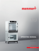
CO2 INCUBATOR ICOMED WITH IVF MODULE
ICO50MED
ICO105MED

Manufacturer and customer service
MEMMERT GmbH + Co. KG
Willi-Memmert Strasse 90-96
91186 Büchenbach
Germany
Phone: +49 (0)9122 925-0
Fax: +49 (0)9122 14585
Internet: www.memmert.com
Customer service:
Service hotline: +49 (0)9171 9792 911
Service fax: +49 (0)9171 9792 979
E-mail: [email protected]
When calling for service enquiries, please state the appliance number given on the nameplate
(see page 10).
Shipping address for repairs:
Memmert GmbH + Co. KG
Customer service
Willi-Memmert Str. 90-96
91186 Büchenbach
Germany
Please contact our customer service department before sending appliances for repair or before
returning equipment, or the shipment may be refused.
© 2020 MEMMERT GmbH + Co. KG
D39322 | Date 01/2020
Subject to change without notice

D39322 | Date 01/2020 1
About this manual
About this manual
Purpose and target audience
These instructions are an addition to the operating manual for the ICOmed CO2 incubator
when using the IVF module. It is intended for use by trained personnel of the owner, who
have the task of operating and/or maintaining the respective appliance.
If you are asked to work on the appliance, read these instructions and the operating manual
for the ICOmed CO2 incubator carefully before starting. Familiarise yourself with the safety
regulations. Only perform work that is described in this manual. If there is something you do
not understand, or certain information is missing, ask your manager or contact the manufac-
turer. Do not do anything without authorisation.
Versions
Due to individual configurations and sizes, illustrations in this manual may be slightly different
to the actual appearance. Function and operation are identical.
Other documents to be observed:
►the operating manual for the ICOmed CO2 incubator
►For operation of the appliance with MEMMERT AtmoCONTROL, observe the separate
software manual
►For service and repair work, observe the separate service manual
Storage and resale
This operating manual belongs with the appliance and should always be stored where per-
sons working on the appliance have access to it. It is the owner's responsibility to ensure that
persons who are working on or are going to work on the appliance know where to find the
operating manual. We recommend that it is always stored in a protected location close to the
appliance. Make sure that the operating manual is not damaged by heat or humidity. If the
appliance is resold or transported and then set up again at a different location, the operating
manual must remain with it.

2 D39322 | Date 01/2020
Contents
Contents
1. Safety regulations 5
1.1 Terms and signs used........................................................................................................... 5
1.1.1 Terms used ........................................................................................................................ 5
1.1.2 Signs used ......................................................................................................................... 5
1.2 Product safety and dangers ................................................................................................ 6
1.3 Intended use ........................................................................................................................ 7
1.4 Requirements of the operating personnel .......................................................................... 7
1.5 Responsibility of the operator .............................................................................................8
1.6 Changes and alterations ...................................................................................................... 8
1.7 Behaviour in case of malfunctions and irregularities .......................................................... 8
1.8 What to do in case of accidents .......................................................................................... 8
1.9 Switching off the appliance in an emergency .................................................................... 9
2. Design and description 10
2.1 Design ................................................................................................................................ 10
2.2 Description ......................................................................................................................... 10
2.3 Standard package .............................................................................................................. 11
3. IVF-Module installation 12
3.1 Additional package for self-installation of the IVF module .............................................. 12
3.2 Assembly ............................................................................................................................ 12
3.2.1 Cleaning .......................................................................................................................... 12
3.2.2 Checking the temperature sensor ................................................................................... 13
3.2.3 Fitting the installation frame .......................................................................................... 13
3.2.4 Insert IVF module ............................................................................................................ 15
3.2.5 Removing the drawers .................................................................................................... 16
3.2.6 Remove IVF module ........................................................................................................17
4. Putting into operation 18
4.1 Connecting the appliance ................................................................................................. 18
4.2 Switching on the appliance ............................................................................................... 18
4.3 Sterilising the appliance .................................................................................................... 18
4.3.1 Preparation ...................................................................................................................... 18
5. Operation 20
5.1 Preparation ........................................................................................................................ 20
5.2 Start the incubation process ............................................................................................. 20
5.3 After the incubation process ............................................................................................. 20
6. Cleaning 21

D39322 | Date 01/2020 3
Safety regulations
1. Safety regulations
1.1 Terms and signs used
In this manual and on the appliance itself, certain common terms and signs are used to warn
you of possible dangers or to give you hints that are important in avoiding injury or damage.
Observe and follow these notes and regulations to avoid accidents and damage. These terms
and signs are explained below.
1.1.1 Terms used
WARNING Warns of a dangerous situation that might lead to death or
serious injuries
CAUTION Warns of a dangerous situation that might lead to moderate
or minor injuries
NOTICE Warns of material damage
1.1.2 Signs used
Danger of elec-
trocution
Fire hazard Gases / vapours Danger of frost-
bite/
cold burns
Warning of gas
bottles
Danger of burns Disconnect the
mains plug
Wear gloves Wear safety
boots
Observe informa-
tion in separate
manual
Information on
first aid
First aid:
Rinse eyes out
Important or
useful
additional infor-
mation

4 D39322 | Date 01/2020
Safety regulations
1.2 Product safety and dangers
The appliances described in this manual are technically sophisticated, manufactured using
high-quality materials and subject to many hours of testing in the factory. They reflect the
state of the art and comply with recognised technical safety regulations. However, there are
still risks involved, even when the appliances are used as intended. These are described below.
WARNING
After removing covers, live parts may be exposed. Touching these
can lead to an electrical shock. Disconnect the mains plug before
removing any covers. Work on the electrical system must only be
performed by qualifi ed electricians.
WARNING
When loading the appliance with an unsuitable load, poisonous
or explosive vapours or gases may be produced. This could cause
the appliance to explode, and people could be severely injured or
poisoned. The appliance may only be loaded with materials / test
objects that do not emit any poisonous or explosive vapours when
heated up.
WARNING
Leaving the door open during operation can cause the appliance to
overheat or pose a fi re hazard. Do not leave the door open during
operation.
WARNING
Depending on operation, the surfaces in the interior of the
appliance and the chamber load may still be very hot after
the appliance is switched off. Touching these surfaces can
cause burns. Wear heat-resistant protective gloves or wait
until the appliance cools down before touching.
WARNING
Gas bottles may burst or explode at high temperatures. Keep the
gas bottles away from open fl ames. Store gas bottles below 50 °C
and ensure that the location is always well ventilated. Prevent water
from penetrating as well as backfl ow into the gas bottles. It is es-
sential that you read the safety notes and instructions of the gas
supplier.
WARNING
Condensation in the electrical components may cause short circuits.
After transporting or storing the device under humid conditions, re-
move it from its packaging and let it ventilate for at least 24 hours in
normal environmental conditions. Do not connect the device to the
mains power during this time.

D39322 | Date 01/2020 5
Safety regulations
CAUTION
Danger of suffocation. CO2 and N2 in high concentrations can have
a suffocating effect. In normal mode, the appliance emits small
amounts of CO2 and N2 to its surroundings. You should therefore en-
sure that the room in which it is installed is properly ventilated. You
will need to extract 250 m³ of air per hour as a minimum. Always
close the stop valve or pressure reducer on the gas bottles if the ap-
pliance is not in operation.
CAUTION
High concentrations of CO2 can cause cold burns or frostbite. Avoid
contact with CO2 gas to the eyes and skin.
CO2 and N2 are not dangerous substances in terms of the German Hazardous Substances
Ordinance (GefStoffV). You should nevertheless familiarise yourself with the applicable safety
regulations prior to handling such gas bottles.
1.3 Intended use
The CO2 incubator ICOmed with IVF module is used to generate and maintain constant ambi-
ent conditions for the in-vitro fertilisation (IVF) application field, especially for the incubation
of oocytes, spermatozoa and zygotes in special culture dishes for IVF application as well as for
gene expression and the biosynthesis of RNA and proteins.
1.4 Requirements of the operating personnel
The incubator may only be operated and maintained by persons who are of legal age, and
who have received instructions for the incubator. Personnel who are to be trained, instructed
or who are undergoing general training may only be active on the incubator under the con-
tinuous supervision of an experienced person.
The incubator may only be transported by persons (fork-lift truck, manual pallet jack), who are
trained for this work and who know the corresponding safety regulations.
Repairs may only be performed by qualified electricians. The regulations in the separate service
manual must be observed.

6 D39322 | Date 01/2020
Safety regulations
1.5 Responsibility of the operator
The operator of the incubator
►is responsible for the flawless condition of the incubator and for the incubator being oper-
ated in accordance with its intended use;
►is responsible for ensuring that persons who are to operate or service the incubator are
qualified to do this, have received instructions about the incubator and are familiar with
this operating manual;
►must know about the applicable guidelines, requirements and operational safety regula-
tions, and train staff accordingly;
►is responsible for ensuring that unauthorised persons have no access to the incubator;
►is responsible for ensuring that the maintenance plan is adhered to and that maintenance
and repair work is properly carried out;
►ensures, for example through corresponding instructions and inspections, that the incuba-
tor and its surroundings are kept clean and tidy;
►is responsible for ensuring that personal protective clothing is worn by operating person-
nel, e.g. work clothes, safety shoes and protective gloves.
1.6 Changes and alterations
No independent conversions or alterations may be made to the incubator. No parts may be
added or inserted which have not been approved by the manufacturer.
Unauthorised changes or alterations result in the EC declaration of conformity losing its valid-
ity, and the incubator may no longer be operated.
The manufacturer is not liable for any damage, danger or injuries that result from unauthor-
ised changes or alterations, or from non-compliance with the provisions in this manual.
1.7 Behaviour in case of malfunctions and irregularities
The incubator may only be used when in a flawless condition. If you as the operator notice
irregularities, malfunctions or damage, put the incubator out of service immediately (see
Chapter 1.9) and inform your superiors.
1.8 What to do in case of accidents
1. Keep calm. Act with determination and consideration. Pay attention to your
own safety.
2. Switch off the incubator and close the valves on the gas bottle.
3. Call a doctor.
4. Start first aid measures. If available: Call a trained first aid helper.
In case of contact with CO2 to the eyes and skin:
Rinse eyes out with water for at least 15 minutes. In case of cold burns, rinse with
water for at least 15 minutes. Cover over in a sterile way. Call a doctor.

D39322 | Date 01/2020 7
Safety regulations
After inhaling CO2:
High concentrations can cause suffocation. Symptoms may include a loss of mobility and
unconsciousness. The victim is not aware of suffocating.
Low concentrations of CO2 can cause accelerated breathing and headaches.
Anyone affected should breathe fresh air, using a breathing device independent of recircu-
lating air. Keep the person warm and calm. Call a doctor. In case of respiratory arrest, use
artificial respiration.
If gas is escaping:
Leave the room immediately, warn others and ventilate the room. If you re-enter the room,
use a breathing device independent of recirculating air if it has not been established that the
atmosphere is harmless.
1.9 Switching off the appliance in an emergency
Press the main switch on the ControlCOCKPIT
(Fig. 1) and disconnect the power plug. This
disconnects the appliance from the power
supply at all poles.
ON
O
O
ON
N
N
N
O
O
N
O
Fig. 1
Switch off the appliance by pressing the
main switch

8 D39322 | Date 01/2020
Design and description
2. Design and description
2.1 Design
1
2
4
3
5
6
7
Fig. 2 Design
1 ControlCOCKPIT with capacitive function keys and LCD displays (for description and opera-
tion see ICOmed operating instructions)
2 Main switch
3 Outlet
4 IVF module
5 Markable drawers
6 Unlocking handle
7 Inner glass door
2.2 Description
The ICOmed CO2 incubator with IVF module is used to generate and maintain constant
ambient conditions for the in-vitro fertilisation (IVF) application field. For this purpose, it is
equipped with a slide-in unit - the IVF module - which in turn contains eight (ICOmed 105)
and six (ICOmed 50) drawers, into which Petri dishes and 4-well plates as well as tube holders
can be inserted on the included inserts.
The drawers in the IVF module can be pulled out individually after opening the door to insert
or remove inserts and preparations.

D39322 | Date 01/2020 9
Design and description
When the door is opened, the temperature, humidity and CO2 control is interrupted until
it closes again.
2.3 Standard package
Standard package
IVF module
Drawer insert for Petri dishes
ICOmed 50: 12 units
ICOmed 105: 16 units
2 holders for IVF tubes
Magnetic foil
Custom calibration certificate

10 D39322 | Date 01/2020
IVF-Module installation
3. IVF-Module installation
3.1 Additional package for self-installation of the IVF module
Additional package for self-assembly
Bottom mounting frame
Top mounting frame
Side mounting frame
(2 pieces included)
Allen key screws M6x70 3 units
Round-head screws M4x8 12 units
3.2 Assembly
Installation is only necessary if the IVF module is not already installed in the ICOmed incubator
at the factory.
3.2.1 Cleaning
The components for the installation frame are cleaned at the factory by Memmert. However,
shipping and packaging may cause contamination.
If necessary, clean the interior of the cabinet and the individual parts of the installation frame
in advance.
The sterilisation process prior to start-up is not basic cleaning for dirt particles.

D39322 | Date 01/2020 11
IVF-Module installation
3.2.2 Checking the temperature sensor
Strong vibrations during transport could result in the
temperature sensors being moved in their holders in
the ceiling of the working chamber. Check whether the
Temperature sensor is located correctly and if neces-
sary, adjust in position in the holders (Fig. 3).
3.2.3 Fitting the installation frame
CAUTION
Risk of injury.
Wear gloves and work shoes.
Required tools
Allen key sizes 2.5 and 5
1. Position the lower mount-
ing frame centrally on the
bottom of the unit so that
the shelf on the front side
protrudes approx. 10 mm
into the interior of the unit.
The fixing screw Ⓐ must face
forward.
oA
Fig. 3 Temperature sensor

12 D39322 | Date 01/2020
IVF-Module installation
2. Slide the side mounting
frame on the left and right
side over the heating bead-
ing. The side installation
frames rest on the lower
installation frame.
3. Slightly tighten the side
mounting frames on both
sides with six M4 x 8 pan-
head screws. Ensure an even
gap between the side and
lower installation frames.

D39322 | Date 01/2020 13
IVF-Module installation
4. Place the upper mounting
frame on the side mounting
frame and slide it in carefully.
The fixing screws Ⓐ must
face forward. The upper
frame rests on the side frame.
5. Tighten the upper mounting
frame evenly on both sides
with six M4 x 8 pan-head
screws.
6. Then tighten all 12 screws
in sequence so that the gap
between the side and top/
bottom mounting frames is
approximately equal.
7. Test whether the mounting
frame is firmly seated.
oA
3.2.4 Insert IVF module
WARNING
Risk of injury due to the weight of the IVF module. The IVF module
50 weighs approx. 25 kg, the IVF module 105 approx. 35 kg.
Always hold the IVF module with both hands.
1. Grip the IVF module by the frame with both hands and insert it into the tube (Fig. 4).
2. Fasten the IVF module with 3 screws M6 x 70 (Fig. 5).
Fig. 4 Insert the IVF module into the tube
with both hands
Fig. 5 Fasten IVF module

14 D39322 | Date 01/2020
IVF-Module installation
3.2.5 Removing the drawers
The drawers can be removed for cleaning purposes and to remove the IVF module.
1. The drawers are secured by a locking mechanism. To pull out a drawer, lift the tab at the
point marked with an arrow and pull out the drawer (Fig. 6).
2. The drawer is secured against being pulled out by the mounting bracket mounted in the
rear area of the drawer. To release the safety device, push the lever upwards to release it
(Fig. 7).
Fig. 6 To pull out a drawer, lift the tab
Fig. 7 Press the safety lever upwards to
remove the drawer

D39322 | Date 01/2020 15
IVF-Module installation
3.2.6 Remove IVF module
WARNING
Risk of injury due to the weight of the IVF module. The IVF module
50 weighs approx. 25 kg, the IVF module 105 approx. 35 kg.
Always hold the IVF module with both hands.
1. Loosen the 3 screws for fastening in the interior with an Allen key (size 5, see Fig. 5).
2. Remove the upper left or right drawer (see section 3.2.5).
3. Reach into the drawer opening and pull out the slide-in unit until the frame is within reach
(Fig. 8).
4. Grip the IVF module by the frame with both hands and pull it out of the tube (Fig. 9).
Fig. 8 Pull the slide in unit out of the drawer
opening
Fig. 9 Pull the IVF module out of
the tube with both hands

16 D39322 | Date 01/2020
Putting into operation
4. Putting into operation
4.1 Connecting the appliance
Connect the appliance to the power, water and CO2 supply as described in the ICOmed oper-
ating manual.
4.2 Switching on the appliance
Switch on the appliance as described in the ICOmed operating manual at the main switch.
4.3 Sterilising the appliance
Before the appliance can be used, it has to be sterilised. Sterilisation programs are stored in
the device. How they are carried out is described in the ICOmed incubator's operating instruc-
tions. Preparation is as described below.
WARNING
Danger of burns! The incubator becomes very hot inside during the
sterilisation process. Do no open door. If you open the door, the on-
going sterilisation process will be terminated and destroyed.
NOTICE
The sterilisation programme is not intended to sterilise the chamber load but only to sterilise
the interior of the appliance. The ICOmed IVF incubator is not a steriliser with respect to the
Law on Medical Products.
4.3.1 Preparation
1. Open the door, pull out the drawer and leave it open for five minutes so that the humidity
can evaporate.
2. Check and make sure that there is no more chamber load in the drawers.
3. Wipe labels if they are present.
4. Place inserts for Petri dishes and/or 4-well plates and tube holders (Fig. 10 and Fig. 11).
Fig. 10 Inserts for Petri dishes and / or
4-well plates inserted
Fig. 11 Tube holder inserted

D39322 | Date 01/2020 17
Putting into operation
5. Close all drawers and the door.
6. Attach magnetic foil to the door (Fig. 12).
7. Carry out the sterilisation program as de-
scribed in the ICOmed incubator's operating
instructions.
NOTICE
Do not leave the appliance unattended during
the sterilisation process.
Fig. 12 Magnetic foil

18 D39322 | Date 01/2020
Operation
5. Operation
5.1 Preparation
Warm the device for 4 hours at 37 °C before incubating (without incubation material, but with
inserted Petri dish holders and media holders as well as media). Do not activate the humidity
control before the chamber has been heated for at least 4 hours. Depending on the use, set
the rest of the parameters (CO2 and O2) (see ICOmed operating instructions).
5.2 Start the incubation process
1. Wipe off any descriptions on the magnetic foil and the drawers.
2. Insert the Petri dishes with the incubation charge.
3. Close the door.
4. Label the outer magnetic film and drawers with whiteboard pens to assign the samples
(do not use permanent markers).
NOTICE
Only open the outer door for checking purposes and otherwise keep the door closed. When
the door is opened, the temperature, humidity and CO2 control is interrupted until it closes
again.
5.3 After the incubation process
Open the appliance, pull out one of the drawers and let the appliance ventilate for 30 min-
utes.
/
