Page is loading ...

68-2154-01 Rev. E
01 19
DP DA2
User Guide
DisplayPort
Distribution Amplifier

Safety Instructions
Safety Instructions • English
WARNING: This symbol,
D
, when used on the product, is
intended to alert the user of the presence of uninsulated dangerous
voltage within the product’s enclosure that may present a risk of
electric shock.
ATTENTION: This symbol,
I
, when used on the product, is
intended to alert the user of important operating and maintenance
(servicing) instructions in the literature provided with the equipment.
For information on safety guidelines, regulatory compliances, EMI/EMF
compatibility, accessibility, and related topics, see the Extron Safety and
Regulatory Compliance Guide, part number 68-290-01, on the Extron
website, www.extron.com.
Sicherheitsanweisungen • Deutsch
WARNUNG: Dieses Symbol
D
auf dem Produkt soll den Benutzer
darauf aufmerksam machen, dass im Inneren des Gehäuses dieses
Produktes gefährliche Spannungen herrschen, die nicht isoliert sind
und die einen elektrischen Schlag verursachen können.
VORSICHT: Dieses Symbol
I
auf dem Produkt soll dem Benutzer
in der im Lieferumfang enthaltenen Dokumentation besonders
wichtige Hinweise zur Bedienung und Wartung (Instandhaltung)
geben.
Weitere Informationen über die Sicherheitsrichtlinien, Produkthandhabung,
EMI/EMF-Kompatibilität, Zugänglichkeit und verwandte Themen finden Sie
in den Extron-Richtlinien für Sicherheit und Handhabung (Artikelnummer
68-290-01) auf der Extron-Website, www.extron.com.
Instrucciones de seguridad • Español
ADVERTENCIA: Este símbolo,
D
, cuando se utiliza en el
producto, avisa al usuario de la presencia de voltaje peligroso sin
aislar dentro del producto, lo que puede representar un riesgo de
descarga eléctrica.
ATENCIÓN: Este símbolo,
I
, cuando se utiliza en el producto,
avisa al usuario de la presencia de importantes instrucciones de uso
y mantenimiento recogidas en la documentación proporcionada con
el equipo.
Para obtener información sobre directrices de seguridad, cumplimiento
de normativas, compatibilidad electromagnética, accesibilidad y
temas relacionados, consulte la Guía de cumplimiento de normativas y
seguridad de Extron, referencia 68-290-01, en el sitio Web de Extron,
www.extron.com.
Instructions de sécurité • Français
AVERTISSEMENT : Ce pictogramme,
D
, lorsqu’il est utilisé sur
le produit, signale à l’utilisateur la présence à l’intérieur du boîtier
du produit d’une tension électrique dangereuse susceptible de
provoquer un choc électrique.
ATTENTION : Ce pictogramme,
I
, lorsqu’il est utilisé sur
le produit, signale à l’utilisateur des instructions d’utilisation ou de
maintenance importantes qui se trouvent dans la documentation
fournie avec le matériel.
Pour en savoir plus sur les règles de sécurité, la conformité à la
réglementation, la compatibilité EMI/EMF, l’accessibilité, et autres sujets
connexes, lisez les informations de sécurité et de conformité Extron,
réf. 68-290-01, sur le site Extron, www.extron.com.
Istruzioni di sicurezza • Italiano
AVVERTENZA: Il simbolo,
D
, se usato sul prodotto, serve ad
avvertire l’utente della presenza di tensione non isolata pericolosa
all’interno del contenitore del prodotto che può costituire un rischio di
scosse elettriche.
ATTENTZIONE: Il simbolo,
I
, se usato sul prodotto, serve ad
avvertire l’utente della presenza di importanti istruzioni di funzionamento
e manutenzione nella documentazione fornita con l’apparecchio.
Per informazioni su parametri di sicurezza, conformità alle normative,
compatibilità EMI/EMF, accessibilità e argomenti simili, fare riferimento
alla Guida alla conformità normativa e di sicurezza di Extron, cod. articolo
68-290-01, sul sito web di Extron, www.extron.com.
Instrukcje bezpieczeństwa • Polska
OSTRZEŻENIE: Ten symbol,
D
, gdy używany na produkt, ma na celu
poinformować użytkownika o obecności izolowanego i niebezpiecznego
napięcia wewnątrz obudowy produktu, który może stanowić zagrożenie
porażenia prądem elektrycznym.
UWAGI: Ten symbol,
I
, gdy używany na produkt, jest przeznaczony do
ostrzegania użytkownika ważne operacyjne oraz instrukcje konserwacji
(obsługi) w literaturze, wyposażone w sprzęt.
Informacji na temat wytycznych w sprawie bezpieczeństwa, regulacji wzajemnej
zgodności, zgodność EMI/EMF, dostępności i Tematy pokrewne, zobacz Extron
bezpieczeństwa i regulacyjnego zgodności przewodnik, część numer 68-290-01,
na stronie internetowej Extron, www.extron.com.
Инструкция по технике безопасности • Русский
ПРЕДУПРЕЖДЕНИЕ: Данный символ,
D
, если указан
на продукте, предупреждает пользователя о наличии
неизолированного опасного напряжения внутри корпуса
продукта, которое может привести к поражению электрическим
током.
ВНИМАНИЕ: Данный символ,
I
, если указан на продукте,
предупреждает пользователя о наличии важных инструкций по
эксплуатации и обслуживанию в руководстве, прилагаемом к
данному оборудованию.
Для получения информации о правилах техники безопасности,
соблюдении нормативных требований, электромагнитной
совместимости (ЭМП/ЭДС), возможности доступа и других вопросах
см. руководство по безопасности и соблюдению нормативных
требований Extron на сайте Extron: www.extron.com, номер по
каталогу - 68-290-01.
安全说明 • 简体中文
警告: D产品上的这个标志意在警告用户该产品机壳内有暴露的危险 电压,
有触电危险。
注意:I 产品上的这个标志意在提示用户设备随附的用户手册中有
重要的操作和维护(维修)说明。
关于我们产品的安全指南、遵循的规范、EMI/EMF 的兼容性、无障碍
使用的特性等相关内容,敬请访问 Extron 网站 www.extron.com,参见 Extron
安全规范指南,产品编号 68-290-01。

安全記事 • 繁體中文
警告: D 若產品上使用此符號,是為了提醒使用者,產品機殼內存在著
可能會導致觸電之風險的未絕緣危險電壓。
注意I 若產品上使用此符號,是為了提醒使用者,設備隨附的用戶手冊中有
重 要 的 操 作 和 維 護( 維 修 )説 明 。
有關安全性指導方針、法規遵守、EMI/EMF 相容性、存取範圍和相關主題的詳細
資訊,請瀏覽 Extron 網站:www.extron.com,然 後 參 閱《 Extron 安全性與
法 規 遵 守 手 冊 》,準 則 編 號 68-290-01。
安全上のご注意 • 日本語
警告:この記号 D が製品上に表示されている場合は、筐体内に絶縁されて
いない高電圧が流れ、感電の危険があることを示しています。
注意:この記号 I が製品上に表示されている場合は、本機の取扱説明
書に 記載されている重要な操作と保守(整備)の指示についてユー
ザーの注意を喚起するものです。
安全上のご注意、法令遵守、EMI/EMF適合性、その他の関連項目に
つ い て は 、エ ク スト ロ ン の ウ ェブ サ イト www.extron.com より
『Extron Safety and Regulatory Compliance Guide』 (P/N 68-290-01) をご
覧ください 。
안전 지침 • 한국어
경고: 이 기호 D, 가 제품에 사용될 경우, 제품의 인클로저 내에 있는
접지되지 않은 위험한 전류로 인해 사용자가 감전될 위험이
있음을 경고합니다.
주의: 이 기호 I, 가 제품에 사용될 경우, 장비와 함께 제공된 책자에
나와 있는 주요 운영 및 유지보수(정비) 지침을 경고합니다.
안전 가이드라인, 규제 준수, EMI/EMF 호환성, 접근성, 그리고 관련 항목에
대한 자세한 내용은 Extron 웹 사이트(www.extron.com)의 Extron 안전 및
규제 준수 안내서, 68-290-01 조항을 참조하십시오.
Copyright
© 2012 - 2019 Extron Electronics. All rights reserved.
Trademarks
All trademarks mentioned in this guide are the properties of their respective owners.
The following registered trademarks®, registered service marks (SM), and trademarks (TM) are the property of RGBSystems, Inc. or
Extron Electronics (see the current list of trademarks on the Terms of Use page at www.extron.com):
Registered Trademarks
(
®
)
Cable Cubby, ControlScript, CrossPoint, DTP, eBUS, EDID Manager, EDID Minder, Extron, Flat Field, FlexOS, Glitch Free, Global Configurator,
Global Scripter, GlobalViewer, Hideaway, HyperLane, IPIntercom, IPLink, Key Minder, LinkLicense, LockIt, MediaLink, MediaPort,
NetPA, PlenumVault, PoleVault, PowerCage, PURE3, Quantum, Show Me, SoundField, SpeedMount, SpeedSwitch, StudioStation,
SystemINTEGRATOR, TeamWork, TouchLink, V-Lock, VideoLounge, VN-Matrix, VoiceLift, WallVault, WindoWall, XTP, XTP Systems, and ZipClip
Registered Service Mark
(SM)
: S3 Service Support Solutions
Trademarks
(
™
)
AAP, AFL (Accu-Rate Frame Lock), ADSP (Advanced Digital Sync Processing), Auto-Image, AVEdge, CableCover, CDRS (Class D
Ripple Suppression), Codec Connect, DDSP (Digital Display Sync Processing), DMI (Dynamic Motion Interpolation), DriverConfigurator,
DSPConfigurator, DSVP (Digital Sync Validation Processing), eLink, EQIP, Everlast, FastBite, FOX, FOXBOX, IP Intercom HelpDesk, MAAP,
MicroDigital, Opti-Torque, PendantConnect, ProDSP, QS-FPC (QuickSwitch Front Panel Controller), Room Agent, Scope-Trigger, ShareLink, SIS,
Simple Instruction Set, Skew-Free, SpeedNav, Triple-Action Switching, True4K, Vector™ 4K, WebShare, XTRA, and ZipCaddy

FCC Class A Notice
This equipment has been tested and found to comply with the limits for a Class A digital
device, pursuant to part15 of the FCC rules. The ClassA limits provide reasonable
protection against harmful interference when the equipment is operated in a commercial
environment. This equipment generates, uses, and can radiate radio frequency energy and,
if not installed and used in accordance with the instruction manual, may cause harmful
interference to radio communications. Operation of this equipment in a residential area is
likely to cause interference. This interference must be corrected at the expense of the user.
NOTE: For more information on safety guidelines, regulatory compliances, EMI/EMF
compatibility, accessibility, and related topics, see the Extron Safety and Regulatory
Compliance Guide on the Extron website.

Conventions Used in this Guide
Notifications
In this user guide, the following are used:
ATTENTION:
• Risk of property damage.
• Risque de dommages matériels.
NOTE: A note draws attention to important information.
Software Commands
Commands are written in the fonts shown here:
^AR Merge Scene,,Op1 scene 1,1 ^B 51 ^W^C
[01] R 0004 00300 00400 00800 00600 [02] 35 [17] [03]
E X!*X1&*X2)*X2#*X2! CE}
NOTE: For commands and examples of computer or device responses
mentioned in this guide, the character “0” is used for the number zero and “O”
represents the capital letter “o”.
Computer responses and directory paths that do not have variables are written in the font
shown here:
Reply from 208.132.180.48: bytes=32 times=2ms TTL=32
C:\Program Files\Extron
Variables are written in slanted form as shown here:
ping xxx.xxx.xxx.xxx —t
SOH R Data STX Command ETB ETX
Selectable items, such as menu names, menu options, buttons, tabs, and field names are
written in the font shown here:
From the File menu, select New.
Click the OK button.
Specifications Availability
Product specifications are available on the Extron website, www.extron.com.
Extron Glossary of Terms
A glossary of terms is available at www.extron.com/technology/glossary.aspx.


Contents
Introduction............................................................ 1
About the DP DA2 .............................................. 1
DP DA2 Features ................................................ 1
Application Diagram ........................................... 2
Panel Features ...................................................... 3
Rear Panel, Features, and Connections .............. 3
Power Supply ................................................. 4
DisplayPort Connectors .................................. 6
Dual Mode DisplayPort ................................... 7
EDID Minder ................................................... 7
RS-232 Control .............................................. 9
Mute Control................................................... 9
Front Panel, Features, and Connections ........... 10
Power LED ................................................... 10
Config USB Port ........................................... 10
Signal and HDCP LEDs ................................ 12
Setup ...................................................................... 13
SIS Commands ................................................... 14
Introduction to SIS ........................................... 14
Symbols Used in this Guide .............................. 15
Error Messages ................................................ 15
Command and Response Table for
SIS Commands ............................................... 16
Updating Firmware ............................................ 18
Downloading and Installing Firmware Loader .... 18
Downloading DP DA2 Firmware ........................ 19
Loading the Firmware to the DP DA2 ................ 20
Resetting Firmware to the Factory
Default Version ................................................ 23
Mounting ............................................................... 24
Desktop Placement .......................................... 24
Rack Mounting ................................................. 24
UL Guidelines for Rack Mounting .................. 24
Rack Mounting Procedure ............................ 24
DP DA2 • Contents vii

DP DA2 • Contents viii

Introduction
This guide describes the function, installation and operation of the DP DA2 distribution
amplifier. Unless otherwise stated, the terms “DA” and “distribution amplifier” refer to the
DPDA2.
This section contains the following information:
• About the DP DA2
• DP DA2 Features
• Application Diagram
About the DP DA2
The DP DA2 provides an Extron distribution amplifier for VESA
®
A DisplayPort signals. It
accepts a single input with data rates up to 10.8 Gbps and, in normal mode, distributes
two identical outputs with resolutions of up to 2560x1600 @ 60 Hz on each output. Input
and output signals can each be carried a maximum of 25feet (7.62 m).
In Extend mode, the DP DA2 outputs an image with a resolution of up to
3840x1080@60Hz extended over two output displays.
The DP DA2 uses the DisplayPort v1.1a standard and is backwards compatible with
earlier specifications. It has EDID Minder for EDID (Extended Display Identification
Data) management, Key Minder for continuous HDCP (High-bandwidth Digital Content
Protection) verification, and can be controlled by RS-232, using the Extron Simple
Instruction Set (SIS) commands.
DP DA2 Features
DisplayPort — In normal mode provides two identical outputs with PC resolutions
up to 2560x1600 @ 60 Hz, with multi-channel audio and HDTV up to 1080p @ 60 Hz,
distributed with embedded multi-channel digital audio signals.
Thunderbolt
™
source support (input) — Thunderbolt sources are backward compatible
with the DPDA2 input with respect to both audio and video, using a DisplayPort to Mini
DisplayPort adapter. Thunderbolt devices are not supported on the DPDA2 outputs.
Signals up to 10.8 Gbps — Supports data rates of either 1.62Gbps (reduced bit rate)or
2.7 Gbps (high bit rate) using one, two, or four lanes.
Dual mode — Allows for interoperability with HDMI, DVI, and VGA display devices.
Provides connectivity between a dual mode DisplayPort-equipped source and HDMI, DVI,
and VGA display devices with an appropriate adapter.
Extend mode — Outputs a single image with a resolution of up to 3840x1080 @ 60 Hz
extended over two output displays.
EDID Minder — Maintains continuous EDID communication with the attached source.
This ensures that the source powers up correctly and maintains a proper video output,
even if the display is off.
Content protection — Supports HDCP. The DPDA2 checks the source and output
displays for HDCP compliance.
DP DA2 • Introduction 1

HDCP visual confirmation — Provides a green signal when encrypted content is sent to
a non-compliant display. A full-screen green signal is sent when HDCP-encrypted content
is transmitted to a non-HDCP compliant display, providing immediate visual confirmation
that protected content cannot be viewed on the display.
Key Minder — Authenticates and maintains continuous HDCP encryption between all
input and output devices to enable simultaneous distribution of a single source signal to
two or more displays.
Automatic input cable equalization — Up to 25 feet (7.6 m) at 2560x1600 @ 60Hz
with Extron DisplayPort cables. Conditions incoming digital signals to compensate for
signal loss from long cables, low quality cables, or source devices with poor DisplayPort
signal output.
LED indicators — Provide real-time feedback and monitoring of key performance
parameters by indicating signal presence and HDCP authentication. The tri-color EDID
LED indicator on the back panel shows whether an internal or external EDID is stored.
RS-232 serial control — Allows control by SIS commands either via the controller or
directly from a PC using the front panel USB port or the rear panel 3-pole captive screw
connector.
Output muting control via RS-232 or contact closure — Provides the capability to
mute one or both outputs at any time. This allows content to be viewed on a local monitor
prior to appearing on the main presentation display.
Application Diagram
12V
0.6A MAX
POWER
EDID
STORE
EXTEND
NORMAL
DEFAULT
STORED
1
RS-232 MUTE
RxTx 1G 2
2
INPUT
REMOTE
EDID
OUTPUTS
DP DA2
Flat Panel Displays
with DisplayPort Inputs
Ext
ron
DP
DA2
Displ
ayPort
Dist
ribution
Am
plier
PC with DisplayPort Output
1
31
42
3
1
42
31
42
2
3
100
LINK
AC
T
COM
IR
INPU
T
RELAY
T
X
RX
R
IPL 250
®
ON
O
FF
D
ISPLAY
MUTE
S
CREEN
UP
S
CREEN
DOWN
VCR
DVD
DOC
CAM
LAPTOP
P
C
TCP/IP
TouchLink Pro
Control System
Figure 1. Typical DP DA2 Application
DP DA2 • Introduction 2

Panel Features
This section describes the panel features and connections of the DP DA2.
• Rear Panel, Features, and Connections
• Front Panel, Features, and Connections
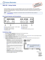
Rear Panel, Features, and Connections
12V
0.6A MAX
POWER
EDID
STORE
EXTEND
NORMAL
DEFAULT
STORED
1
RS-232 MUTE
RxTx 1G2
2
INPUT REMOTEEDIDOUTPUTS
DP DA2
AABBCCD
DE
EFFGGH
H
Figure 2. DP DA2 Rear Panel
A
Power — Connect the provided power supply to this 2-pole, 3.5 mm captive screw
connector (see Power Supply on page 4).
B
Input — Connect the source device to this female DisplayPort connector (see
DisplayPort Connectors on page 6).
C
Outputs — Connect up to two display devices to these female DisplayPort
connectors (see DisplayPort Connectors on page 6).
D
EDID Minder LED — Lights red, amber, or green, showing current EDID Minder
state (see EDID Minder LED on page 8).
E
EDID Minder Store push-button — This recessed button activates EDID store (see
Recording EDID on page 7).
F
EDID Minder DIP switches — Used to configure the EDID Minder features (see DIP
switches on page 8).
G
RS-232 control — Connect the transmit (Tx), receive (Rx), and ground (G)
connectors of this 5-pole, 3.5 mm captive screw connector to a control PC (see
RS-232 Control on page 9).
H
Mute control — Connect the ground (G) and either pin 1 (to mute output1) or pin 2
(to mute channel 2) (see Mute Control on page 9).
DP DA2 • Panel Features 3

Power Supply
The provided 12 VDC power supply connects to this 2-pole, 3.5mm captive screw
connector (see figure 2,
A
, on page 3). The front panel power LED lights green when
the unit is receiving power.
1. Connect the captive screw connector from the power supply to the power receptacle.
Rear Panel
Power Receptacle
DC Power Cord
Captive Screw Connector
AC Power Cord
+12 VDC
External
Power Supply
(12 VDC, 1 A )
SECTION A–A
Ridges
Smooth
Power Supply
Output Cord
AA
3/16"
(5 mm) Max
.
12V
- - A MAX
POWER
12V
- - A MAX
POWER
–
Figure 3. Power Connections
ATTENTION:
• Always use a power supply provided by or specified by Extron. Use of an
unauthorized power supply voids all regulatory compliance certification and may
cause damage to the supply and the end product.
• Utilisez toujours une source d’alimentation fournie ou recommandée par Extron.
L’utilisation d’une source d’alimentation non autorisée annule toute conformité
réglementaire et peut endommager la source d’alimentation ainsi que le produit
final.
• If not provided with a power supply, this product is intended to be supplied by a
power source marked “Class 2” or “LPS” and rated 12VDC, minimum 1.0 A.
• Si le produit n’est pas fourni avec une source d’alimentation, il doit être alimenté
par une source d’alimentation de classe 2 ou LPS, avec une tension nominale
12 Vcc, 1,0 A minimum.
• Extron power supplies are certified to UL/CSA 60950-1 and are classified as
LPS (Limited Power Source). Use of a non-LPS or unlisted power supply will
void all regulatory compliance certification.
• Les sources d’alimentation Extron sont qualifiées UL/CSA60950-1 et sont
classéesLPS(LimitedPowerSource). L’utilisation d’une source d’alimentation
non-listée ou non-listéeLPS annulera toute certification de conformité
réglementaire.
• Unless otherwise stated, the AC/DC adapters are not suitable for use in air
handling spaces or in wall cavities. The power supply is to be located within the
same vicinity as the Extron AV processing equipment in an ordinary location,
Pollution Degree 2, secured to the equipment rack within the dedicated closet,
podium, or desk.
• Sauf mention contraire, les adaptateurs AC/DC ne sont pas appropriés pour
une utilisation dans les espaces d’aération ou dans les cavités murales. La
source d’alimentation doit être située à proximité de l’équipement de traitement
audiovisuel dans un endroit ordinaire, avec un degré2 de pollution, fixé à un
équipement de rack à l’intérieur d’un placard, d’une estrade, ou d’un bureau.
DP DA2 • Panel Features 4

ATTENTION:
• The installation must always be in accordance with the applicable provisions of
National Electrical Code ANSI/NFPA 70, article 725 and the Canadian Electrical
Code part 1, section 16.
• Cette installation doit toujours être en accord avec les mesures qui s’applique
au National Electrical Code ANSI/NFPA70, article725, et au Canadian
Electrical Code, partie1, section16.
• The power supply shall not be permanently fixed to building structure or similar
structure.
• La source d’alimentation ne devra pas être fixée de façon permanente à une
structure de bâtiment ou à une structure similaire.
• Power supply voltage polarity is critical. Incorrect voltage polarity can damage
the power supply and the unit. Identify the power cord negative lead by the
ridges on the side of the cord (figure 4).
• La polarité de la source d’alimentation est primordiale. Une polarité incorrecte
pourrait endommager la source d’alimentation et l’unité. Repérez le pôle négatif
du cordon d’alimentation grâce aux stries sur le côté du cordon (illustration 4).
• The length of the exposed wires in the stripping process is critical. The ideal
length is 3/16 inches (5 mm). Any longer and the exposed wires may touch,
causing a short circuit between them. Any shorter and the wires can be easily
pulled out even if tightly fastened by the captive screws.
• La longueur des câbles exposés est primordiale lorsque l’on entreprend de les
dénuder. La longueur idéale est de 5mm (3/16inches). S’ils sont un peu plus
longs, les câbles exposés pourraient se toucher et provoquer un court circuit.
S’ils sont un peu plus courts, ils pourraient sortir, même s’ils sont attachés par
les vis captives.
• Do not tin the wire leads before installing into the connector. Tinned wires are
not as secure in the connector and could be pulled out.
• Ne pas étamer les conducteurs avant de les insérer dans le connecteur. Les
câbles étamés ne sont pas aussi bien fixés dans le connecteur et pourraient
être retirés.
2. Connect the AC power cord of the power supply unit to a 110 or 220 VAC electrical
source. When the unit is receiving power, the front panel LED shows a green light.
DP DA2 • Panel Features 5

DisplayPort Connectors
Connect the source device to the input socket (see figure 2,
B
on page 3) and up
to two display devices to the output sockets (
C
). The connector wiring is shown in the
figure and table below.
Pin Function Notes
1
ML Lane 0 (p) Main Link Lane 0 (positive)
2
GND Ground
3
ML_Lane 0 (n) Main Link Lane 0 (negative)
4
ML_Lane 1 (p) Main Link Lane 1 (positive)
5
GND Ground
6
ML_Lane 1 (n) Main Link Lane 1 (negative)
7
ML_Lane 2 (p) Main Link Lane 2 (positive)
8
GND Ground
9
ML_Lane 2 (n) Main Link Lane 2 (negative)
10
ML_Lane 3 (p) Main Link Lane 3 (positive)
11
GND Ground
12
ML_Lane 3 (n) Main Link Lane 3 (negative)
13
CONFIG1 Connected to Ground 1
14
CONFIG2 Connected to Ground 1
15
AUX CH (p) Auxiliary Channel (positive)
16
GND Ground
17
AUX CH (n) Auxiliary Channel (negative)
18
Hot Plug Hot Plug Detect
19
Return Return for Power
20
DP_PWR Power for Adapters (3.3 V 500 mA)
The DP DA2 supports data rates of either 1.62 Gbps (reduced bit rate) or 2.7Gbps (high
bit rate), using either one, two, or four lanes. The DP DA2 supports mini DisplayPort
and dual mode DisplayPort through the use of the appropriate adapters and cables (not
provided).
Thunderbolt sources are backward compatible with the DPDA2 input with respect to both
audio and video, using a DisplayPort to Mini DisplayPort adapter. Thunderbolt devices are
not supported on the DPDA2 outputs.
An equalizer on the input compensates for a poor source signal and allows a cable run of
up to 25 feet (7.62 m).
The DP DA2 supports resolutions up to 2560x1600 @ 60 Hz. In addition, a resolution of
3840x1080 @ 60 Hz can be carried over two outputs and displayed as extended view. If
audio is available from the source, it will also be available to the output devices.
The Key Minder feature ensures that the DP DA2 is fully HDCP compliant. The source
negotiates with the DP DA2 input and the display negotiates with the DP DA2 output. The
input HDCP LED lights green when the source is encrypted and has been authenticated
by the DP DA2 unit. Each output HDCP LED lights green when HDCP has been
authenticated between the source and the corresponding output. The LEDs will not light
if the source does not require HDCP encryption or if the sink device connected to that
output is not HDCP compliant.
NOTE: Extron recommends that the displays connected to outputs 1 and 2 are the
same model or have the same native resolution.
119
220
DP DA2 • Panel Features 6

Dual Mode DisplayPort
The DP DA2 supports dual mode for interoperability with VGA, DVI, and HDMI display
devices. Appropriate adapters are required.
NOTES:
• Certain VGA displays that lack a scaler do not work properly with Dual Mode
DisplayPort.
• In some applications using DisplayPort adapters, the DP DA2 may be unable
to capture EDID of the display connected to output 1. Use SIS commands to
adjust the DDC speed (see page 15).
EDID Minder
During boot up, the source device uses the auxiliary channel to obtain
Extended Display Identification Data (EDID) from the display device.
This allows the output signal to match the resolution and refresh rate
of the display device.
EDID Minder allows the user to store and use EDID values for another
display device to ensure the output signal is compatible with both the
display devices.
EDID Store push-button and LED
Recording EDID
NOTE: A source must be connected to the input to record EDID from the sink
device.
1. Connect the display device that will provide EDID information to output 1.
2. Power on the display and the DP DA2.
3. Set DIP switch 1 (on the left) in the Stored (down) position (see DIP switches on
the following page for more information). The EDID Minder LED (see figure 2,
D
, on
page 3) lights red until you start recording EDID.
4. Press the EDID Store push-button (
E
). The button is recessed (you may need a
small screwdriver).
The EDID Minder LED lights amber while the EDID is being stored and turns green
when the recording process is successfully completed.
EDID information is read from the display device connected to output 1. The recorded
EDID is stored in non-volatile memory and is retained after a power cycle or after a
new display device is connected to output 1.
The new EDID is then available when DIP switch1 is in the Stored position. Each
time a new EDID is recorded, it overwrites the existing data and is available when
DIPswitch1 is in the Stored position.
NOTE: If the EDID for a display device is corrupted or cannot be read, the
DP DA2 will continue to use the currently stored EDID.
EDID
STORE
EXTEND
NORMAL
DEFAULT
STORED
EDID
DP DA2 • Panel Features 7

EDID Minder LED
The LED shows the status of the EDID recording process:
• Off — DIP switch 1 is set to Default.
• Red — DIP switch 1 is set to Stored, but external EDID has not been stored (the
factory default EDID is still present).
• Amber — New EDID information is currently being read and stored.
• Green — External EDID has been stored.
DIP switches
Two DIP switches (see figure 2,
F
, on page 3) are used to select which of two
EDID values is presented to the source device (DIP switch 1) and whether the output is in
normal or extend mode (DIP switch 2).
DIP switch 1 — In the Default (up) position, the EDID value is the factory-stored
default, with a native resolution of 1080p and 2-channel audio. In the Stored (down)
position, the most recently recorded EDID value is used (this file overwrites previously
stored values). Before any other EDID file is recorded, the factory default EDID is also
stored here.
To record EDID, follow the instructions in Recording EDID on the previous page.
DIP switch 2 — In the Normal (down) position, the DP DA2 provides two duplicate
outputs of up to 2560x1600 @ 60Hz and multi-channel audio. If the DIP switch is in
the Extend (up) position, the DPDA2 provides an image with a resolution of up to
3840x1080 @ 60 Hz and 2-channel audio extended over two output displays.
Available Extend Mode Resolutions Resolution per Output
3840x1080 @ 60 Hz 1920x1080 @ 60 Hz
3360x1050 @ 60 Hz 1680x1050 @ 60 Hz
2880x900 @ 60 Hz 1440x900 @ 60 Hz
2560x1024 @ 60 Hz 1280x1024 @ 60 Hz
Summary
DIP Switch 1 DIP Switch 2 Function
Stored (down) Normal (down)
Stored EDID is used and normal mode
Default (up) Normal (down)
Default EDID is used and normal mode
Extend (up)
Extended mode
NOTE: If DIP switch 2 is set to Extend, DIP switch 1 is non-functional
DP DA2 • Panel Features 8

RS-232 Control
The RS-232 controls use the first three pins of the rear panel 5-pin captive
screw connector labeled Remote (see figure 2,
G
, on page 3). The pins
are labeled Tx, Rx, and G. The ground (G) is shared with the mute controls.
Connect the DP DA2 to a control PC, as follows:
Host PC Pin DP DA2 Pin
5 (Gnd) G
2 (Rx) Tx
3 (Tx) Rx
NOTE: Connect a ground wire between
To Computer or
Control System
RS-232 Port
DP DA2
Rear Panel
RS-232 Port
9-pin
Connector
NOTE: If you use cable that has a drain
RS-232 MUTE
RxTx 1G2
REMOTE
the DP DA2 and the computer or
control system.
wire, tie the drain wire to ground at
both ends.
(Rx) Receive Pin to Tr ansmit (Tx) Pin 3
G Ground Pin 5
(Tx) Transmit Pin to Receive (Rx) Pin 2
Alternatively, use the Config USB Port to connect to the PC (see the next page). These
ports are used to send commands from the control PC or Control system to the DA (see
SIS Commands on page 14).
Mute Control
The mute controls use the third, fourth, and fifth pins of the Remote 5-pin
captive screw connector (see figure 2,
H
, on page 3). They are labeled
G, 1, and 2. The ground (G) is shared with the RS-232.
Ground pin 1 (to mute output 1) or pin 2 (to mute output 2).
RS-232 MUTE
RxTx 1
G2
REMOTE
RS-232
RS-232 MUTE
RxTx 1
G2
REMOTE
Mute
DB9 Pin Locations
Female
51
96
DP DA2 • Panel Features 9

Front Panel, Features, and Connections
DP DA2
DISPLAYPORT DISTRIBUTION AMPLIFIER
CONFIG
AABBCC
INPUT
OUTPUTS
SIGNAL
HDCP
12
Figure 4. DP DA2 Front Panel
A
Power LED — Lights green when the unit is receiving power (see Power LED).
B
Config USB port — Connect this USB port to a control PC (see Config USB Port).
C
Signal and HDCP LEDs — Provide information about the signal and HDCP
encryption status of the input and outputs (see Signal and HDCP LEDs on
page 12).
Power LED
The Power LED (see figure 4,
A
) lights green when the unit is receiving power.
Config USB Port
Connecting to the USB Port
The USB mini B port (
B
) is located on the DP DA2 front panel. It can be used to connect
the distribution amplifier to a host computer for updating firmware or for configuration
using SIS commands. Alternatively, use the RS-232 Control (see page 9). For
complete information about SIS commands, see SIS Commands on page 14.
1. Connect a USB A to mini B cable between the USB Config port on the front panel of
the DPDA2 and the USB port of the PC.
USB Cable
USB AUSB Mini B
USB 1
USB
Ports
Computer
DP DA2 Front Panel
DP DA2
DISPLAYPORT DISTRIBUTION AMPLIFIER
CONFIG
INPUT
OUTPUTS
SIGNAL
HDCP
1 2
Figure 5. Connecting a PC to the DP DA2 Front Panel USB Port
2. If this is the first time a DP DA2 has been connected to the PC, the Found New
DP DA2 • Panel Features 10

Hardware Wizard opens (see figure 6). The first screen offers to search the Web for
the appropriate driver needed to communicate with the distribution amplifier via the
USB port. This is not necessary if the USB driver is already on your PC.
Figure 6. Found New Hardware Wizard Welcome Screen
• Select Yes, this time only to connect the PC to Windows Update only this
one time.
• Select Yes, now, and every time I connect a device to automatically
connect to Windows Update every time the DP DA2 connects to this USB port.
• Select No, not this time if you do not want to connect to Windows Update
(for example, if the driver is already on the PC).
3. Click Next. The next screen of the Wizard opens unless No, not this time was
selected in step 2:
Figure 7. Installing the Software Automatically
4. Select Install the software automatically (Recommended) and click Next.
DP DA2 • Panel Features 11

NOTE: You do not need to insert an installation disc.
The PC locates the driver needed and installs it in the correct location on the hard
drive.
5. When the Completed screen appears, click Finish to close the wizard.
NOTE: The wizard appears only on the first occasion you connect the DP DA2
to that USB port. The wizard will reappear if you connect the DP DA2 to a
different USB port or if you connect a different piece of equipment, requiring a
different driver, to the same USB port.
6. Configure the DP DA2 as required.
Signal and HDCP LEDs
See figure 4,
C
on page 10.
Signal LEDs
Input Signal LED — Lights green when main link activity is
detected from the source device connected to the input.
Output Signal LED — Lights green when a main link signal
is being transmitted to at least one of the display devices
connected to the outputs.
HDCP LEDs
Input HDCP LED — Lights green when the source is HDCP encrypted and authenticated
by the DP DA2.
Output HDCP LED — Lights green when the connected display device is HDCP
compliant.
NOTE: The HDCP LEDs will not light if the source device does not require HDCP
encryption or if the display devices are not HDCP compliant.
INPUT
OUTPUTS
12
SIGNAL
HDCP
DP DA2 • Panel Features 12
/