Page is loading ...

Page | 1

Page | 2
Contents
1. Preface ...................................................................................................................................................... 3
2. How It Works ............................................................................................................................................. 4
3. Safety Instructions ..................................................................................................................................... 5
4. Installation ................................................................................................................................................. 7
4.1 Installation Diagram ....................................................................................................................... 7
4.2 Installation Site ............................................................................................................................... 8
4.3 Ducts Installation ........................................................................................................................... 9
4.4 Electrical Installation .....................................................................................................................10
4.5 Plumbing .......................................................................................................................................11
4.6 Air-Cooled Condenser Installation .................................................................................................12
4.7 Pipe Installation .............................................................................................................................13
5. Water Chemistry .......................................................................................................................................14
5.1 Pool Water Chemistry ...................................................................................................................14
6. Start-up Check List ....................................................................................................................................14
6.1 Pre-Start Checklist .........................................................................................................................14
6.2 Start-Up.........................................................................................................................................15
7. Operation .................................................................................................................................................16
7.1 How to Control ..............................................................................................................................16
7.2 Run-Mode Menu ...........................................................................................................................17
7.3 Alarms Menu ................................................................................................................................20
7.4 Sensors Off Set Menu ....................................................................................................................20
7.5 Run-state Menu ............................................................................................................................21
7.6 Curves Menu .................................................................................................................................21
7.7 On/Off Menu ................................................................................................................................22
8. Alarm and Troubleshooting .......................................................................................................................23
9. Circuit Diagram .........................................................................................................................................25
10. Dimension and Parts ...............................................................................................................................26
10.1 Description of Parts and Dimensions .............................................................................................26
11. Maintenance ...........................................................................................................................................28
11.1 Overview .......................................................................................................................................28
11.2 Daily Maintenance .........................................................................................................................28
11.3 Monthly Maintenance ...................................................................................................................28
11.4 Annual Maintenance .....................................................................................................................28
12. Technical Specification ............................................................................................................................29
13. GUARANTEE CARD ..................................................................................................................................30

Page | 3
1. Preface
Thank you for choosing a Evo SOLACE UNIVERSAL Multi-functional Commercial Pool Dehumidifier &
Ventilation unit. This is the operation manual for models C-250 to C-1800.
Please read this manual carefully as it provides useful operation and maintenance information that
will maximise the benefits your dehumidifier can offer. Keep the manual in a safe place. You may
want to refer to it again.
The Solace Universal Multi-Functional Commercial Pool Dehumidifier & Ventilation unit is designed
to provide an environment that is both comfortable and cost effective. It controls unwanted
humidity in the pool enclosure and helps to prevent unsightly condensation from forming on
surfaces.
HUMIDITY CONTROL
If the space temperature is below the desired set point, the heat recovered during dehumidification is directed to the
air reheat coil for space heating. If the pool water temperature is also below the set point, some of the recovered heat
is directed to the pool water condenser (for pool heating mode only) for pool water heating. If neither air heating nor
pool water heating is required, the recovered heat can be directed to an auxiliary air conditioning condenser if the
system is so equipped. If the system does not include an auxiliary air conditioning condenser, the unit will direct the
recovered heat to the air reheat coil until the need for dehumidification is satisfied.
SPACE HEATING
When the compressor is running, space heating will continue until the space temperature reaches the set point. The
controller will activate the auxiliary space heating system if the unit is unable to satisfy the heating need with heat
recovered during dehumidification.
SPACE COOLING (OPTIONAL)
If space cooling is required and the unit is equipped with an auxiliary air conditioning condenser (air-cooled or water-
cooled), the controller will activate the space cooling mode of operation. In this mode, the heat removed from the
space air will be directed to the auxiliary air conditioning condenser. The air-cooling mode of operation is independent
of the need for dehumidification.
WATER HEATING (OPTIONAL)
If the pool water temperature is also below the set point, some of the recovered heat is directed to the pool water
condenser for pool water heating. Heating can only take place during the dehumidification when heat is captured in the
refrigeration circuit. This is only available on the mode pool heating, which is equipped with a pool water condenser.
FRESH AIR AND ENERGY RECOVERY
The unit includes energy conservation strategies such as heat recovery, airflow measurement and CO2 based control
help control costs while improving indoor air quality.
STANDARD ITEMS FACTORY SUPPLIED FOR FIELD INSTALLATION
• Microprocessor control interface device
• Outside air temperature sensor
• Humidity sensor
• Air quality sensor
SYSTEM OPTIONS
• Remote Air-cooled condenser for space air conditioning
• Water-cooled condenser
• Pool water heating
• Cooling/heating coils

Page | 4
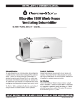
2. How It Works
MULTI FUNCTIONAL DEHUMIDIFIER REFRIGERANT SYSTEM SCHEMATIC
The fan draws in warm, moist air from the pool enclosure. This air passes through the evaporator
(dehumidification) coil and gives up heat energy to the refrigerant which is in a cool, liquid state.
This exchange of energy causes the air temperature to fall below its dew point, resulting in
moisture condensation on the evaporator coil. The moisture formed falls into the unit’s condensate
drain pan.
The refrigerant enters the unit’s compressor, where it is compressed into a hot gas. While in the
compressor, the refrigerant absorbs the energy used to operate the compressor. This hot gas
refrigerant then travels either through an air reheat coil, the pool water condenser or to an
optional auxiliary air conditioning condenser, which may be either air or water cooled. If air heating
is called for, the air reheat coils is used. The hot refrigerant exchanges energy with the cooler,
dehumidified air coming from the evaporator coil. This causes the temperature of the air to rise for
heating.
If pool water heating is required, the hot gas flows into a pool water condenser, where it adds
energy to the incoming pool water. This heats the pool water while the refrigerant is condensed
into a warm liquid. If space cooling is called for, the refrigerant flows to the auxiliary air
conditioning condenser by passing the air reheat coil and pool water condenser and allowing cool
air from the evaporator coil to provide space cooling.

Page | 5
3. Safety Instructions
Read the Safety Instructions carefully before operation.
WARNING
Incorrect handling could cause a
serious hazard such as death,
serious injury etc. with a high
probability.
CAUTION
Incorrect handling could cause a
serios hazard depending on the
conditions.
Meaning of symbols used in this manual are shown as
below.
Prohibited – be sure not to do.
Important - Be sure to follow this
instruction
Be sure to ground
Be sure to disconnect the power
plug
Never step on the unit or place
anything on them
Danger of electrical shock
Do not insert fingers or objects
DO NOT disconnect/connect the power during operation.
This may cause a fire due to sparks, etc.
When an abnormality (smell of burning, etc.) occurs, stop
the unit and disconnect the power or turn off the breaker.
If the unit continues to be operated in an abnormal
condition, it may cause a fire or hazards.
Apply Grounding. Do not connect a grounding wire to a
gas pipe, water pipe, lightning rod or ground wire of a
telephone. If a grounding is incorrect, it may cause an
electronic shock.
WARNING
No connection in the middle of power cord or extend
the power cord. Multifunctional socket is forbidden to
be used.
Remove dirt from the power terminal. If dirt adheres
to the terminal or fixed is incomplete it may cause a
fire or electric shock.
Do not scratch or process the power cord. Do not put
heavy objects on the power cord, heat it or process it.
The cord may become damaged and cause a fire or
electric shock.
Consult your dealer for installation.
Do not insert fingers or objects into the air inlet and
air outlet. Since the fan rotates at high speed, this may
cause an injury.
Repair or relocation must not be done by the
customer. If done incorrectly, it may cause fire,
electric shock, water leakage and other hazards.
Consult your dealer if you are unsure of anything.

Page | 6
WARNING
Do not pull the power cord. Use the screwdriver to
disconnect it. The core wire of the power cord may be
disconnected, and it may cause a fire.
When the unit is to be cleaned, switch off and disconnect
the power or turn off the breaker.
Since the fan rotates at high speed during operation, it
may cause an injury.
Install an earth leakage breaker when the
unit is installed in a humid location. If the
earth leakage breaker is not installed, it
may cause an electrical shock.
The customer must not install this unit themselves. If
done incorrectly it may cause a fire, electric shock, water
leakage etc.
Ensure that you consult your dealer.
Do not apply an insecticide or flammable spray. It
may cause a fire or deformation of the cabinet.
Do not clean the unit with water. Water may enter the
unit and degrade the insulation which can cause
electric shock.
When the unit is not going to be used for a long time,
disconnect the power or turn off the breaker and
make sure there is no water inside the unit. If not dirt
may collect and cause a fire hazard.
Do not install the unit where there is flammable gas.
Do not operate switches with wet hands.
CAUTION
Do not operate for a long time in the rain. It will shorten
the lifespan of the unit.
Do not step on the unit and do not put anything on it.
Do not step onto an unstable bench when
attaching/detaching the panel

Page | 7
4. Installation
4.1 Installation Diagram

Page | 8
4.2 Installation Site
Select a suitable location for the unit, where the unit will not be subject to any damage.
a) The unit must be mounted on a flat and level foundation capable of supporting the entire operating
weight of the equipment.
b) The location must not contain corrosive-chemical storage or connect to any space that contains corrosive-
chemical storage.
c) The location must not include a natatorium or spa room, or any space where the exterior of the unit
would be exposed to chloramines outgassing from a pool.
d) Ensure that water cannot collect under the unit, it is recommended that units are installed on plinths
100mm above finished floor level. This also aids condensate drainage.
e) Please allow adequate clearance to service panels on the unit; recommended 800mm minimum.
f) Ensure loose debris such as leaves, grass cuttings, etc will not block air inlet grilles.
g) Consider protection from extreme weather conditions if installed externally.
h) Inadequate working spaces may compromise workplace safety. Inadequate working spaces may preclude
proper maintenance.

Page | 9
4.3 Ducts Installation

Page | 10
4.4 Electrical Installation
1.ELECTRICAL SAFETY
It is important to ensure that all aspects of the installation comply with the latest I.E.E. Regulations. It is also
important to ensure that any remote devices which terminate within the pool hall are of the type and
voltage as specified in the latest I.E.E. Regulations. The machine should be installed in accordance with
EMC2004/108/EC.
2.PROTECTED SUPPLY
Whilst not mandatory, we recommend that an R.C.C.B. is always fitted or that the supply is to local electricity
authority recommendations, and that all ducting is bonded in accordance with these regulations. The supply
to the machine should incorporate fuses or motor rated circuit breakers (type GU, FAZC) to specified rating
(see data sheet)
H.R.C. Fuses are recommended. An isolator must be fitted within clear view of the machine and not more
than 2 meters away. The isolator must have a minimum of 3mm air gap when in the off position.
3.POWER SUPPLY
Power supply of the dehumidifier must consistent with the power supply described in the circuit diagram. If
inconsistent power supply is connected, the dehumidifier will not be guaranteed either in performance or
warranty.
Note: The voltage must be measured at the dehumidifier mains terminals with all the fans/compressors
running at the rated condition.
4.CORRECT CABLE SIZING
The cable supplying electricity to a machine with a given load must increase in cross sectional area (CSA) as
the length increases in order that the voltage drop within the cable does not exceed recommended limits.
Cable sizing should be calculated by an approved electrician with due consideration to I.E.E. and local codes
of practice.

Page | 11
4.5 Plumbing
CONDENSATE DRAIN
The condensate drip tray in the dehumidification unit collects the water removed by the dehumidification
process, It is therefore necessary to ensure that the dehumidification unit is placed on a level plinth so that
the condensate can run away and not overflow the edges of the drip tray inside the machine. The drain pipe
should run away with adequate fall to waste and must incorporate a 'U' trap.
BOILER PLUMBING
Suitable breakable couplings, isolation, and drain down valves should be Installed in the boiler water flow
and return pipes local to the dehumidification unit. Refer to the boiler manufacturer’s instructions before
designing the pipework system.
IMPORTANT GENERAL CONDITIONS
1) Do not route water pipes across service access panels or air inlet/outlets.
2) The water circuits to and from the dehumidification unit should be capable of maintaining the
specified water flow limits required by the machine.
3) All pipework must be adequately supported with allowance for expansion and contraction especially
with regard to the plastic pipework.
4) It is recommended that when installing water systems, the last connections to be made should be
adjacent to the dehumidification unit to avoid undue stresses on the unit connections.

Page | 12
4.6 Air-Cooled Condenser Installation
The most important consideration which must be considered when deciding upon the locations of air-cooled
equipment is the provision for a supply of ambient air to the condenser, and removal of heated air from the
condenser area. Where this essential requirement is not adhered to, it will result in higher head pressures,
which cause poor operation and possible eventual failure of equipment. Units must not be located in the
vicinity of steam, hot air, or fume exhausts.
WALLS OR OBSTRUCTIONS
The unit should be located so that air may circulate freely and not be re-circulated. For proper air flow and
access all sides of the units should be a minimum of “W” away from any wall or obstruction. It is preferred
that this distance be increased whenever possible. Care should be taken to see that ample room is left for
maintenance work through access doors and panels. Overhead obstructions are not permitted. When the
unit is in an area where it is enclosed by three walls, the unit must be installed as indicated for units in a pit.
MULTIPLE UNITS
For units placed side by side, the minimum distance between units is the width of the largest unit.
1. The installation platform requirement of air cool condenser (only for the model including air cooling
function)
2. Spacing requirement. As for the machine will exchange heat, the unit must be installed at open area with
good air flow. At the same time, the space distance of heat exchanger air inlet side can’t less than 1500mm,
air outlet space distance can’t less than 3000mm.
3. Outdoor installation platform Requirements. Height deviation for each meter is not more than 1mm. The
total deviation of the platform is not more than 5mm. Bearing standard: Each square meter is not less
than1ton.
4. The distance of copper connection between indoor unit Max 15m.

Page | 13
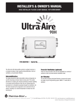
4.7 Pipe Installation
Installation of the outdoor air-cooled condenser should only be done by a qualified refrigeration mechanic
familiar with this type of work. Many service problems can be avoided by taking adequate precautions to
provide an internally clean and dry system and by using procedures and materials that conform to
established procedural standards.
1. Materials
• Use clean, dehydrated, refrigeration-grade copper tubing for all refrigerant lines. Hard drawn tubing should be
used where no appreciable amount of bending around pipes or obstructions is necessary. If soft copper tubing
must be used, care should be taken to avoid sharp bends which may cause restrictions and excessive refrigerant
pressure drops.
• Use long radius elbows wherever possible with one exception - short radius elbows should be used for any traps
in the hot gas riser.
• Braze all copper to copper joints with a phosphorus-copper alloy material such as Silfos 5 or equivalent. Do not
use soft solder.
• During brazing operations flow an inert gas, such as nitrogen, through the lines to prevent internal oxidation
scaling and contamination.
• Support refrigeration lines at intervals with suitable hangers, brackets or clamps.
• Pack glass fiber insulation and a sealing material around refrigerant lines, where they penetrate a wall, to
reduce vibration and to retain some flexibility.
• The liquid line and discharge line should not be in contact with one another. If the installing contractor must tie
these lines together because of an installation requirement, the contractor must insulate them from each other
to prevent heat transfer. Because the discharge line is hot during system operation, precautions should be
taken to avoid personnel injury.
2. Sizing
• The lines must be sized and routed so that oil is carried through the system. Using smaller lines than
recommended will give excessive pressure drops, resulting in reduced capacity and increased power
consumption. Oversized lines could result in an oil flow problem within the system and possible compressor
damage.
• Excessive pressure drops in the liquid line may cause flashing of the refrigerant and a loss of a liquid seal at the
expansion valve inlet. A reduction in capacity may then occur because the presence of gaseous refrigerant will
partially block the expansion valve. Using hot gas and liquid line sizes recommended in the Air Cooled
Condenser section for these units and the proper system refrigerant charge will prevent this problem.
• Discharge lines should be designed to prevent condensed refrigerant and oil from draining back to the
compressor during OFF cycles.
NOTE
The size of the Copper
Pipe: 2pcs of 25mm, 2pcs
of 19mm

Page | 14
5 Water Chemistry
5.1 Pool Water Chemistry
Water chemistry in swimming pools is critical for the health of the bathers and the condition of the
enclosure and components. An enclosure with poor water chemistry has a noticeable “chlorine” smell, which
is an indication of high chloramines in the air. Not only does this have an effect on the water, but it affects
the bathers and the air they breathe.
Recommended Pool Water Chemistry
Acidity pH
pH
7.2 – 7.8
Total Alkalinity, as CaCO
3
ppm
80 – 120
Total Hardness, as CaCO
3
ppm
150 – 250
Total Dissolved Solids
ppm
1000
Maximum Salt Content
ppm
8000
Free Chlorine Range
ppm
1 -2 Domestic
Free Chlorine Range
ppm
3 – 6 Commercial
Superchlorination
max
30ppm for 24 hours
Bromine
ppm
2 – 5
Baquacil
ppm
25 – 50
Ozone
ppm
0.9 Max
Maxiumum Copper Content
ppm
1
Aquamatic Ionic Purifier
ppm
2 Max
6 Start-up Check List
6.1 Pre-Start Checklist
Before starting the unit, be sure that the following items have been completed.
• Ensure there is enough space to install the unit. See “Installation”, for installation recommendations.
• Inspect the packing to be sure it is completed. If damaged, please send a report to your dealer. Protect the
unit if installation is delayed.
• Check to be sure that all packaging materials have been removed from the unit.
• Check that the unit physical installation (ducting, piping, fans, fan valve, panel etc.) is in accordance with
the recommendations of the Installation section.
• Ensure the manual and other necessary documents are completed.
• Check that the condensate drain is connected.
• Ensure that the space air temperature of the pool enclosure is not lower than 22°C, and the temperature
of the pool water is at least 21°C
• If the unit is equipped with the auxiliary air-cooled air conditioning condenser, ensure that it has been
correctly wired and piped and that the control wiring has been connected between the unit and the ACC
unit.

Page | 15
• If the unit is equipped with the auxiliary water-cooled air conditioning condenser, ensure that proper
water flow and temperature are available. Check the water flow direction into and out of the unit.
• Make sure that the fan belt(s) are tight and the fan scroll turns freely in the blower housing.
• Ensure that the pool water temperature sensor has been properly installed.
• Ensure the pressure of pressure gauges is higher than 15kg/cm2 (22psi).
• Ensure that proper pool water flow and pressure are available (for pool heating only). Check the water flow
direction into and out of the unit. Make sure that the unit is down line from the filter and up line from the
chemical feed system.
• Verify electrical power and control connections are in accordance with local codes. Check for proper power
supply and a properly sized and installed fused disconnect switch located within sight of the unit (in 10 m).
6.2 Start-Up
1. After making sure that all personnel are clear of the unit and the water flow to the unit is OFF, turn on the
unit electrical disconnect. When the blower motor starts, verify that it is rotating in the proper direction. If it
is backwards, turn off power to the unit, reverse any two of the power leads, and reapply power.
2. When the blower is running in the correct direction, measure the current draw of the motor. Make sure it
does not exceed the FLA value listed on the motor nameplate. Record the current value(s). If the value is too
high, the static pressure in the supply duct may be too low and the motor pulley will need to be adjusted.
3. Disconnect power from the dehumidifier unit. Re-tension the blower belt. Turn on the pool water supply
to the unit. Use valves in the water line to set the flow rate to the range called out on the unit’s data plate.
After correct water flow has been established, reapply power to the unit.
NOTE: Excessive flow rate can erode the pool water condenser.
WARNING!
HIGH VOLTAGE is used in the operation of this equipment. DEATH OR SERIOUS INJURY may result if
personnel fail to observe precautions. Work on electronic equipment should not be undertaken unless the
individual(s) has (have) been trained in the proper maintenance of the equipment and is (are) familiar with
its potential hazards. Shut off power supply to equipment before beginning work and follow lockout
procedures. When working inside equipment with power off, take special care to discharge every capacitor
likely to hold dangerous potential. Be careful to not contact high voltage connections when installing or
operating this equipment.
NOTE
LOW VOLTAGE - DO NOT be misled by the term “low voltage.” Voltages as low as 50 volts may cause death
4. Use the main menu to access the detailed status display. Choose the “AUTO” or “MANUAL” mode to
access the detailed status display.
5. Put the unit into air heating mode by setting the humidity set point to 60% and the air temperature set
point to 28°C above the current temperature in the space.
6. Set the pool water temperature set point to 27°C. This should cause the unit to run in water heating
mode. The compressor will start approximately at least six minutes after power is applied to the unit.
Measure the current draw of the compressor. It should be less than the RLA value listed on the data plate.
Also measure the voltage at the unit’s power connections.

Page | 16
7. Change the water temperature set point lower/higher than 27°C. This should cause the unit to change to
air heating mode.
8. If the unit is equipped with an auxiliary air-cooled air conditioning condenser, change the air temperature
set point lower/higher than current air temperature. The unit should change from air heating mode to air
cooling mode. Check to be sure that the remote air cooled condenser fan.
9. Add the calculated additional refrigerant and oil charge. The temperature of the supply air from the unit
should drop after a minute or two. Allow the unit to run for at least ten minutes in this mode. Record the
performance data of Air Cooling.
10. If the unit is equipped with an auxiliary air conditioning condenser, change the water temperature set
point lower/higher than current air temperature. This should cause the unit to change to air cooling and
water heating mode. Allow the unit to run in this mode for at least ten minutes. Record the performance
data of Air Cooling and Water Heating.
11. Adjust the air temperature, relative humidity, and water temperature (with pool heating) set points to
the design values.
12. The start-up procedure is now complete and the unit is fully operational.
7 Operation
7.1 How to Control
After application of power to the control system, image will appear for approximately 10 seconds followed
by an initial startup screen as shown below:
Touch the screen will lead to password enter: The initial user password is 111111

Page | 17
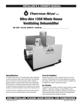
7.2 Run-Mode Menu
1) AUTO
Under this mode selection, the unit will run automatically by dehumidification and air heating,
dehumidification and water heating, dehumidification and air cooling.
The above screen contains basic information of the status and target set point status displays:
Space Temp: Room (space) temperature in℃
Space Humid: Room (space) relative humidity in %
Pool Temp: Pool water temperature in ℃
SysSta: The running status
CtrlMode: The current operation status

Page | 18
2) MANUAL
WARNING
Manual mode operation should only be performed by a qualified HVAC service technician.
Improper use will cause system damage and possibly hazardous operation
Under this mode selection, the unit will run on the selective mode
The above screen contains basic information of the status and the selective running mode. There are three
options to choose:
Manual Humidity: Off/On
Ventilation Only: Off/On
Manual Fresh Air: Off/On
There are three different running modes to choose:
Dehu&A-Heat: Dehumidification and air(space) heating mode
Dehu&W-Heat: Dehumidification and pool water heating mode, for those with pool water heating function
Dehu&A-Cool: Dehumidification and air(space) cooling mode, for those with air/water cooled condenser

Page | 19
• SpaceTempDiff: The temperature difference of room (space) temperature in℃
• SpaceHumidDiff: The humidity difference of room (space) relative humidity in %
• PoolTempDiff: The temperature difference of pool water temperature in℃
• AuxAirHeatDif: The temperature difference for auxiliary air(space) heating in℃
• AuxPoolHeatDif: The temperature difference for auxiliary pool water heating in ℃

Page | 20
7.3 Alarms Menu
The alarms screen provides information on all the faults that have occurred in the dehumidifier. It can be
used for troubleshooting by an experienced HVAC technician.
The dehumidifier may stop when the fault occurs, Press the reset button after the fault has been eliminated
to go back to normal operation
7.4 Sensors Off Set Menu
The offset screen is to calibrate different sensors to a known standard. The signed value of this parameter is
added to actual value read from the sensor
/