Repotec RP-MC301B20 Owner's manual

Category
Network media converters
Type
Owner's manual

This manual is also suitable for

1
Brief introduction
Many thanks for purchasing Fast Ethernet optical
transceiver! This product supports
IEEE802.3UI100Base-Tx/Fx protocol, as well as full
duplex and half duplex mode. This manual is for 100M
transceivers. The following purchasing guide is for
customers reference.
Purchasing guide for optical transceivers
Model
Specifications
UTP-MM
10/100M adaptive, multi-mode 2km, ST/SC/FC/LC
UTP-SM
10/100M adaptive, single mode 20km, ST/SC/FC/LC
UTP-SM
10/100M adaptive, single mode 40km, ST/SC/FC/LC
UTP-SM
10/100M adaptive, single mode 60km, ST/SC/FC/LC
UTP-SM
10/100M adaptive, single mode 100km, ST/SC/FC/LC
Packing list
Please check the following items in the package before
installing the transceiver.
Fast Ethernet optical transceiver 1set
AC/DC adapter (external) 1pcs
User manual 1copy
Please contact the dealer immediately for any loss or
damage to the above items.
Installation
1. Interface
RJ-45 interface
The transmission media adopts CAT5 twisted-pair with
typical length of 100 meter. It features the function of
automatically identifying the through line and cross wire
Fiber interface
SC/ST fiber interface is of duplex mode type, including two
interfaces, namely TX and RX. When the two sets of
optical transceiver are interfaced or connected to switch
with fiber interface, the fiber is in cross connection, namely
"TX-RX", "RX-TX" (direct butting for single optical fiber).
2. Connection
The network device (work station, hub or switch) with
RJ-45 interface is connected to RJ-45 jack of optical
transceiver through twisted-pair. And the multi/single mode
fiber is connected to SC/ST fiber interface of the optical
transceiver. Then switch on. The corresponding LED is on
for correct connection. (See the table below for the LED
indicator lamp)
Figure 1 Schematic drawing of connection
Explanation for LED indicator lamp
LED indicator lamps serve as device monitoring and
trouble display. The following is the explanation for each
LED indicator lamp.
LED
indicator
lamp
Status
Explanation
FX
Link/Act
On
Connection status display for fiber link.
ON indicates that Fiber link is in correct
connection.
Blink
Active status display of fiber link
Blink indicates packet goes through Fx end.
TX
Link/Act
On
Connection status display for electric link.
ON indicates that electric link is in correct
connection.
Blink
Active status display of TP link
Blink indicates packet goes through TP end.
FDX
On
Transceiver works in the full duplex mode.
Off
Transceiver works in the half duplex mode.
PWR
On
Power is on and normal.
FX100
On
Transfer rate of optical interface is 100Mbps.
TX100
On
Transfer rate of electric interface is 100Mbps.
Off
Rate of electric interface is 10Mbps
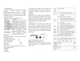
Transmission characteristics of single fiber transceiver
Product
model
(WDM)
Optical
wavelength
(nm)
Receiving
sensitivity
(dbm)
Transmission
distance (km)
UTP-SM
(25km)
1310/1550
1550/1310
<-34dBm
25
UTP-SM
(40km)
1310/1550
1550/1330
<-38dBm
40
UTP-SM
(60km)
1310/1550
1550/1330
<-38dBm
60
2
Fiber transmission features:
Product
model
(WDM)
Optical
wavelength
(nm)
Optical
power
(dBm)
Sensibility
(dBm)
Distance
UTP-MM
850/1310nm
>-18dBm
<-31dBm
2km
UTP-SM 25
1310nm
>-15dBm
<-34dBm
25KM
UTP-SM 40
1310nm
>-8dBm
<-38dBm
40KM
UTP-SM 60
1310nm
>-5dBm
<-38dBm
60KM
UTP-SM 100
1550nm DFB
>0dBm
<-38dBm
100KM
Main features
1. In conformity to IEEE 802.3 10 Base-T standard.
In conformity to IEEE 802.3u 100 Base-TX/FX standard
2. Max. 1Mb buffer memory built in chip.
3. Back pressure flow control for full duplex IEEE802.3 X and half
duplex.
4. Automatic identification of MDI/MDI-X line.
5. In conformity to safety code of FCC and 15 CLASS A and CE
MARK
Technical parameters:
1. Standard Protocol: IEEE802.3 10 Base-T standard
IEEE 802.3u 100Base-TX/FX standard
2. Connector: one UTPRJ-45connector, one SC/ST connector
3. Operation mode: full duplex mode or half duplex mode
4. Power supply parameter: outside: 5V DC 1A
5. Environmental temperature: 0-60
6. Relative humidity: 5%-90%
7. TP cable: Cat5 UTP cable
8. Transfer fiber:
multi-mode: 50/125, 62.5/125 or 100/140μ m
single mode:: 8.3/125, 8.7/125, 9/125 or 10/125μ m
9. Dimensions:
External power supply: 26mmx 71mm x 94mm
Cautions:
1. This product is suitable for indoor application.
2. Put on the dust cover of fiber interface when not used.
3. It is forbidden to stare at the TX fiber-transfer end with naked eyes.
4. Single optical fiber transceiver must be used in pair (See the
attachment description in delivery).
Trouble shooting:
1. Device is not matched. Please select the corresponding network
device according to the transfer rate of the product (10Mbps or
100Mbps) when connected to other network devices (network card,
hub, switch).
2. Line loss is excessive during the fiber wiring. Excessive loss in
connector plug-in and fiber soldering welding and excessive
intermediate nodes may cause excessive loss rate or abnormal
operation.
DIP SWITCH
*Toggle ON pin 1 to LFP is enable; OFF is disable
*Toggle ON pin 2 to Store and forward switch is enable
OFF pin 2 to Modified cut-through switch mode is enable
*Toggle ON pin 3 to auto-negotiation mode is enable
OFF pin 3 to force the TX port work 10/100Mbps, full/ half duplex
*Toggle ON pin 4 to TX is work 10Mbps, OFF is 100Mbps
*Toggle ON pin 5 to TX is work half duplex, OFF is full duplex
*Pin 6 is NC
Fast Ethernet Optical
Transceiver
User manual
(Do not use until you read this manual carefully)
  • Page 1 1
  • Page 2 2

Repotec RP-MC301B20 Owner's manual

Category
Network media converters
Type
Owner's manual
This manual is also suitable for

Ask a question and I''ll find the answer in the document

Finding information in a document is now easier with AI