Page is loading ...

Ø 1-½"
drain
max. 15 feet
Ø ¾" or 1" discharge
Ø 1 ½" vent
drain
Optional extension
pipe for installing
macerator behind
a wall
1
2
3
1
2
4
5 6
7
✓
✓
✓
✓
×
✓
×
×
×
×
✓
×
max 18”
max 18”

SANIACCESS2
120 V - 60Hz - 1/2 HP
IP44 - MAX. 4.5 Amps -
C
US
L
CB
J K
D K
B
J
K
C
D
K
1" PVC
(32 mm)
A
J
B
J
C
K
K
D
B J
¾" PVC
(28 mm)
¾" CPVC
(22 mm)
x1
A
B
C
F
E
D
G
x1 x1 x1 x2 x2 x4
H
x1
20x32
J
x2
32x55
L
x5
25x40
K
x2
P
x1
O
x1
N
x1
90x110
M
x1
I
x1
16 1/2"
15-3/4"
10 1/2"
6 5/8"
9"
6 -3/4"
7 -1/4"
6 5/8"
SANIACCESS 2 USA
MASSE:
A4
FEUILLE 1 SUR 1
ECHELLE:1:10
No. DE PLAN
TITRE:
REVISION
NE PAS CHANGER L'ECHELLE
MATERIAU:
DATE
SIGNATURE
NOM
CASSER LES
ANGLES VIFS
FINITION:
SAUF INDICATION CONTRAIRE:
LES COTES SONT EN MILLIMETRES
ETAT DE SURFACE:
TOLERANCES:
LINEAIRES:
ANGULAIRES:
QUAL.
FAB.
APPR.
VERIF.
AUTEUR
0
3
6
9
12
15 max
feet / pieds
30 60 120 180 240 270 300
feet / pieds
feet/pieds
50 60 70 80 90 100 110 120 l/min
15 20 25 30 US galon/min
VERTICAL DISTANCE
(DISTANCE VERTICALE)
FLOW RATE (DÉBIT)
15
12
9
6
3
0

Access to
Blade System
1
2
3
4
5
✓

Access to
Pressure
Sensing
System
1
2
✓
3
4
Microswitch
Capacitor

21d
21c
3536 34
56
64
28b
31
28b
37
11
9
10
20
13
63
5a
4
61
8
6
3
14
39
40
15
38
16
17
19
42
41
2b
2a
24 23
75
2c
21a
28b
28b
29
28b
66
28c
67
28c
1
7
55
54
2c
12
53
IMPORTANT/ IMPORTANTE
DO NOT RETURN ANY MERCHANDISE TO THE VENDOR
NE PAS RETOURNER DE MARCHANDISE AU VENDEUR
NO REGRESE NINGUNA MERCANCÍA AL VENDEDOR
For customer Service, Returns or Technical Questions, please call Saniflo’s Technical support toll-free at
800-571-8191 (USA) or 800-363-5874 (CDN).
Pour le service client, les retours ou toute question technique, merci d’appeller le service technique de Saniflo
au numéro suivant : USA 800-571-8191 or CDN 800-877-8538.
Para servicio al cliente, devoluciones o preguntas técnicas, por favor llame al soporte técnico de Saniflo sin cargo al 800-571-
8191 (USA) o 800-363-5874 (CDN).
This product must be installed in strict accordance with local plumbing codes.
Product should be installed by a licensed plumber.
Le produit doit être installé dans le respect des règlements sanitaires locaux.
Le produit doit être installé par un plombier qualifié.
El producto debe ser instalado en estricto acuerdo con los códigos locales de plomería. El producto debe ser instalado por un plomero con licencia.
For service or for further inquiries, please call or contact one of the following addresses:
Pour le service et d’autres demandes de renseignements, veuillez appeler à l’une des adresses indiquées ci-dessous :
United States Canada
SFA-SANIFLO INC. SFA-SANIFLO INC.
105 Newfield Avenue, Suite A
1-685 Speedvale Avenue West
Edison, NJ 08837
Guelph, ON
N1K 1E6
Toll Free USA: 1-800-571-8191 Toll Free Canada : 800-353-5874
Numéro sans frais : 800-877-8538 Français
Telephone USA: 1-732-225-6070 Téléphone : 519-824-1134
Fax: 1-732-225-6072 Télécopieur : 519-824-1143
E-mail.:
Courriel :
Web Site: www.saniflo.com Site Web : www.saniflo.ca or/ou www.saniflo.ca/fr

II
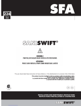
GENERAL DESCRIPTION
The macerator/pump unit is a residential pumping
system for a toilet and bathroom fixtures. It can
simultaneously receive wastewater from sanitary
fixtures such as a sink, but only one toilet per unit.
This macerator is designed for the disposal
of human waste, toilet paper and water. They
are not intended to be used for the disposal of
kitchen waste or from pump appliances such as
a dishwasher or washing machine. Installed and
used correctly, this system will give consistent and
reliable service. This system must discharge into
a minimum 3/4” or 1” sanitary drain pipe. This
system will pump up to 15 feet vertically and/or
150 Ft horizontally, with a minimum 1/4” per foot
gravity fall constantly throughout the horizontal run
to the point of discharge.
There is an extension pipe available from Saniflo
which is 18” in length and is used to install the
pump behind a wall. It attaches to each end of the
toilet and macerator for a secure fit.
Note : The macerator can be installed right
behind the toilet or further away using the optional
extension pipe.
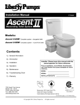
IV
DIMENSIONS & DISCHARGE
CAPACITY
See Page 2
6. When the point of discharge into the soil stack
is lower than the base of the unit, a vacuum relief
valve may need to be fitted at the highest point of
the pipe run in order to avoid siphonage.
7. The macerating unit cannot accept without
damage the disposal of sanitary items such as
condoms, tampons, sanitary pads, cottons swabs,
etc.
8. Any drain pipe leading into the pump shall have
a minimum 1/4” per foot gravity fall. Any horizontal
discharge pipe shall also have this minimum pitch.
9. The total run on the discharge pipe shall be no
less than 3 ft (combined) before it drains into a
larger stack.
10. The discharge pipe work should not be installed
with a diagonal upward slope.
III
INSTALLATION ADVICE
1. All discharge pipe work must be connected
to the soil stack by an appropriate and approved
connection (a “wye” fitting is preferable). Note that
the connection into a horizontal soil stack shall be
through the top of the pipe.
2. The discharge pipe from the macerating system
shall be an independent line as no other drain pipe
shall tie into it.
3. Any initial horizontal pipe run from the unit, prior
to the vertical lift, should not exceed 18 inches.
Note: After the first vertical run, any run afterwards
should be in a horizontal man- ner with the required
slope. Therefore, you cannot change directions in
an upward vertical manner.
4. Use long sweeping 90 degree elbows or two
45 degree elbows back-to-back to create the 90
degree turn.
5. The macerator shall be positioned on the same
level and adjacent to the toilet.
V
TOILET ASSEMBLY
1. The toilet tank is provided with the fill and flush
valve assembled in the tank, however, please
ensure that all connections are tightened.
2. Place the macerating unit in the desired spot
and connect all inlet and outlet waste piping to
the unit. (See section VII - Connection of the
Discharge Pipe).
3. Place the spigot outlet of the toilet bowl firmly
against the white accordion connector and mark
the floor through the holes in the bowl.
4. Remove bowl and bore two holes approximately
2 1/4” deep with a 5/16” masonry drill bit. Insert
plastic plugs into holes. If the floor is wood, bore a
pilot hole with a 1/4” drill bit.
5. Place the bowl in front of the macerating unit
and pull the accordion gasket (H) all the way onto
the rear spigot outlet. Attach with supplied clamp.
Check that gasket and clamp are even all around.
(See section VIII - Preparing the Macerating
Unit).
6. Move the bowl over the holes in floor. Slip the
plastic china protectors over the lag screws. Tighten
lag scvrews (do not over tighten) and snap plastic
cover caps in place.
7. Locate the tank to bowl kit and place foam
gasket on the spud of the tank and over nut. Place
tank on top of the bowl. Insert screws and gasket
through the tank and tighten nuts underneath. Do
not over tighten as this may damage the china.
8. Connect the water supply hose to the fill valve.
9. All pipe work must be rigid be rigid: SCH 40 pipe
(PVC, CPVC, Copper). Pipe supports should not be
less than three feet apart.
Note that the unit as well as most of the pipes and
connections should have easy accessibility.
I
INTRODUCTION
This macerator/pump is manufactured in a factory
which is quality certified to ISO 9001. To benefit
from the advantages provided by this new
generation system, it is important to comply with
the installation instructions.
EN
IMPORTANT ADDITIONAL
INFORMATION
VII
CONNECTION OF THE
DISCHARGE PIPE
These systems are provided with a discharge elbow
which has a built-in check valve (A), a flexible
discharge hose (B), a plastic coupling (C) and a
step-down rubber connection (D). Follow these
steps to connect to your discharge pipe. When
securing clamps utilize a socket wrench in place of
a screw driver to ensure firm leak proof connections.
1. Insert the larger end of the plastic discharge
elbow (A) into the rubber discharge hose coming
out from the top of the pump.
2. Rotate the discharge to any direction and secure
the base of the elbow with a clamp (L).
3. Connect the flexible hose (B) to the smaller end
of the discharge elbow and secure with a clamp (J).
For 3/4” CPVC (22 mm)
4. Insert the discharge pipe inside the flexible hose
(B) and secure with a clamp (J).
For 3/4” PVC (28 mm)
4. Insert the smaller end of the plastic coupling (C)
inside the flexible hose (B); secure with clamp (J).
5. Connect the step-down rubber connection (D) to
the other end of the plastic coupling (C); secure with
a clamp (K).
6. Insert the discharge pipe inside the step-down
rubber connection (D) and secure with clamp (K).
For 1” PVC (32 mm)
4. Insert the smaller end of the plastic coupling (C)
inside the flexible hose (B); secure with clamp (J).
5. Connect the step-down rubber connection (D) to
the other end of the plastic coupling (C); secure with
a clamp (K).
6. Cut off the end of the step-down rubber
connection to fit the 1” pipe; secure with clamp (K).
Note: Install a ball valve in the discharge line in
order to facilitate the removal of the unit. If you want
the unit to pump vertically and horizontally, you
may calculate that 3 Ft of vertical lift is equivalent
to 30 Ft of horizontal run. Note that all horizontal
runs require a 1/4” per foot gravity fall. Each bend
or change in direction causes minor losses which
must be deducted from the discharge performance
(i.e. reduce discharge height by 3 Ft for each 90
degree turn). Use long sweeping 90 degree elbows
or two 45 degree elbows back-to-back to create the
90 degree turn. Do not use 90 degree elbows.
VI
NORMAL OPERATING CYCLE
As the flush is operated or as the lavatory
discharges, the water and waste enter the unit
and the water level begins to rise, triggering the
micro- switch in the pressure chamber. This in turn
activates the motor. The shredded waste is picked
up by the impeller and discharged through a 3/4”
or 1” be rigid: SCH 40 pipe (PVC, CPVC, Copper) to
a sanitary sewer or soil stack.
Safety note: For safety, the macerating unit should
never be activated with the lid removed.

IX
CONNECTION TO
A VENT SYSTEM
The macerating unit must be vented. It has a
1-1/2” inlet on the side of the case meant for this
connection. It must be connected to a vent system
according to your local plumbing codes.
Install the provided 90 degree rubber elbow (O) on
this inlet to connect to the vent pipe and secure
with clamps (L). Note that all fixtures connected to
the system must also be vented.
Warning: Do not use an air admittance
valve or a mechanical spring-loaded venting
device, as these devices are one-way
valves. The air pressure in and outside the
macerating unit must be equal.
X
CONNECTION OF SINK
The macerating unit is equipped with an additional
1-1/2” inlet on the side of the case. This inlet is
used to connect the drain pipe of a sink to the
macerating unit. Use the provided 1-1/2” x 1-1/2”
coupling (I) when connecting a sink. Secure this
connection with the provided clamps (L) once they
are installed.
Note: The actual distance between the p-trap of
the additional fixture and the macerating unit
determines the necessary clearance to install the
p-trap and elevation required to ensure a minimum
gravity flow of ¼” per foot.
EN
VIII
PREPARING THE
MACERATING UNIT
Follow steps on page 3.
XV
MAINTENANCE
(For qualified personnel only)
1. If the unit needs to be opened or if the motor
needs to be removed, please pry open the lid for
easy access. There will be a gasket in between the
lid and the casing which prevents any leakage in
the unit.
2. Note that the motor is filled with dielectric oil.
Do not remove it or replace with regular oil. Please
note that the distributor purposely does not keep
seals, bearings or oil in stock. If the cap which
holds the oil in place is removed, warranty is voided
automatically.
3. When closing the lid, make sure to grease or
lubricate the lid seal with soapy water or dish soap.
The lead seal must be inserted on the inner seams
of the inside of the lid. Once you have the lid almost
in place, work yourself around the lid tapping down
on the lid with a rubber mallet or block.
XIV
RETURN AND REPAIR OF
THE MACERATING UNIT
In the event that the unit needs to be returned for
service, please call for possible options, or to inquire
about an authorized repair shop in your area. When
you are required to return the macerating unit to
the manufacturer or repair shop, please ensure
that prior to shipping, the unit has been cleaned
and disinfected inside and outside. A labor charge
will be in effect for cleaning ($50.00).
Please package the macerating unit properly with
adequate shock absorbent material around it.
If any repairs are done outside the warranty period,
or when the user has damaged the macerating
unit, you will be apprised of repair costs.
XIII
ACCESS TO MAIN
COMPONENTS
(For qualified personnel only)
The macerating unit is very reliable and with normal
use, it is assured to provide service for several
hundred thousand cycles. However, there may be
instances when some little intervention may be
required.
Warning: Before attempting any work, please
make sure to unplug the unit from the power
supply.
1. If a foreign object falls inside the macerating unit
and gets clogged in the blade system, please follow
the steps on page 5 in order to remove it.
Note: The service panel on the left side can be
removed using the tool provided.
Warning: Do not attempt to remove the object
with your hand, use pliers for this purpose.
2. If the capacitor, microswitch or membrane needs
to be replaced, please follow the steps on page 6.
Note: The service panel on the right side can be
removed using the tool provided.
Warning: Before attempting any work, please
make sure to unplug the unit from the power
supply.
These three components are considered to be part
of the pressure sensing section of the pump. In
case of questions on how to replace these, please
call the technical support number listed on the
cover of this manual.
plastic bags, metal such as nails, hairpins, wood,
building materials, kitty litter or anything that
could halt or damage or corrode the unit.
Disregarding the above might damage the
macerating unit and shall void your warranty.
Do not hang bleach blocks or hydrochloride
cleaners in the toilet tank. These solutions
have been shown to deteriorate the plastic and
neoprene components of the flush and fill valves,
and may cause leaks. In the event of a power loss
do not use the toilet or any other sanitary fixture
connected to the macerating unit since it will not
work until the power is restored.
The toilet works as a conventional flushing
toilet and needs no maintenance in normal use.
However, there is nothing wrong with cleaning out
the macerating unit once a year. Use Saniflo lime
and scale remover where hard water is present. Do
not use bleach (Be careful not to let water enter the
electrical cord opening).
The macerating unit starts automatically once the
toilet is flushed or the hand basin is discharged.
Whenever the unit is not to be used for long periods
of time (vacation, power failure, maintenance, etc.)
turn off the water supply to the tank and flush the
unit to evacuate the water. No leakage into the bowl
should ever be permitted from the tank.
In areas, which are prone to freezing, the total
system must be properly winterized. This includes
the draining of all pipes, the toilet tank, bowl and the
macerating tank. The macerating system is simple
to winterize. Pour a jug of plumber’s antifreeze into
the tank and flush the toilet. This will cause the
macerating unit to activate and all remaining water
will be replaced by plumber’s anti-freeze. No parts
or labor are warranted when a breakdown occurs
due to freezing.
Ensure that there are no faucets left open. Drops
will eventually fill up the pump and as a result, the
motor will activate repeatedly.
XII
ACTIVATING
THE UNIT/USAGE
1. Ensure that the toilet is free of building debris
prior to activating.
2. Open the water shut-off valve and let the tank fill
up.
3. Ensure the power supply is on.
4. Flush several times with intervals in between
depositing a few sheets of toilet paper into the bowl.
There should be no paper remaining in the bowl
after each flush.
The normal domain of application of SFA macerating
units only concerns the disposal of human waste,
toilet paper and water.
Warning:
Do not discharge any acids, alkaloids,
solvents painting, paint strippers, food waste,
XI
CONNECTION TO THE
ELECTRICAL SUPPLY
All wiring should be in accordance with the
applicable electrical code in your territory. The
macerating system requires a single-phase 120-volt,
15 amp. supply. When installed in a bathroom, the
receptacle should be 40 inches away (in a straight
line) from a shower or bathtub. Connect only to a
receptacle protected by a ground fault circuit
interrupter (GFCI).
Warning: Risk of electric shock - this pump is
supplied with a grounding conductor and
grounding type attachment plug to reduce the
risk of electrical shock. Be certain that it is
connected only to a properly grounded-type
receptacle.

LIMITED WARRANTY
2 Year Warranty from Date of Purchase
Subject to the terms and conditions set out below, SFA-SANIFLO INC., (hereafter designated the
as the Company) warrants that it will repair or replace the product or any of its component parts,
at the Company’s discretion if it deems that the product or part it is defective or does not meet the
rated performance due to a maufacturing or material default.
If replacement is to be issued, this will only be extended to the first year starting from the date of
purchase. Warranty repairs will apply after such date up to the warranty’s date of conclusion.
TERMS AND CONDITIONS
The conditions of this warranty are the following:
• The product must be installed in accordance with the use described in the enclosed
manuals.
• The product must be connected to a single phase 120V, 60Hz electrical outlet and was not
subject to any negligence, accident or exposure to harmful products or substances.
• The alleged defect or fault must be reported either to the installer or to the Company
during the warranty coverage period.
• The warranty coverage period is valid for 2 years.
PART OR PRODUCT EXCHANGE
The product may be exchanged without cost only at the sales outlet where it was purchased subject
to the following conditions:
• The customer must have an “authorized return number” from the manufacturer in order to
validate exchange.
• The customer must produce proof of purchase to validate exchange.
LIMITATIONS
1.Fill and flush mechanism are guaranteed as per OEM warranty only.
2.Vitreous china are guaranteed only for a factory defect.
3. Cost of disconnection and reconnection (ie labor charges) are not covered by the warranty
and are end-users responsibility.
4. Cost of mail or freight when a part or parts of the system have to be repaired at the
company are not covered by this warranty.
5. In no event shall the company be liable for any special, incidental or consequential
damage, loss, or injury of whatsoever nature or kind arising from or in connection with the
product or any component thereof.
6. The guarantee is transferable only when the product remains at the same premises as
where it was installed initialy.
Except as set forth in this Limited Warranty, the company disclaims all other warranties, express
or implied, with respect to the product or any component thereof including, but not limited to, all
implied warranties for merchantability and fitness for a particular purpose.
For Service and other inquiries, please call either of the addresses listed below.
United States Canada
SFA-SANIFLO INC. SFA-SANIFLO INC.
105 Newfield Avenue, Suite A
1-685 Speedvale Avenue West
Edison, NJ 08837
Guelph ON
N1K 1E6
Toll Free: 1-800-571-8191 Customer Toll Free: 800-363-5874 English
Customer Toll Free: 800-877-8538 French
Telephone: 732-225-6070 Telephone: 519-824-1134
Telefax: 732-225-6072 Telefax: 519-824-1143
Email:
Email:
Web Site: www.saniflo.com Web Site: www.saniflo.ca
Canada
Canada
/