TRIM & FASCIA 190, 440, 540 & 2000 SERIES
• LP SmartSide Ploughed Fascia is a trim product available in ber
substrate.
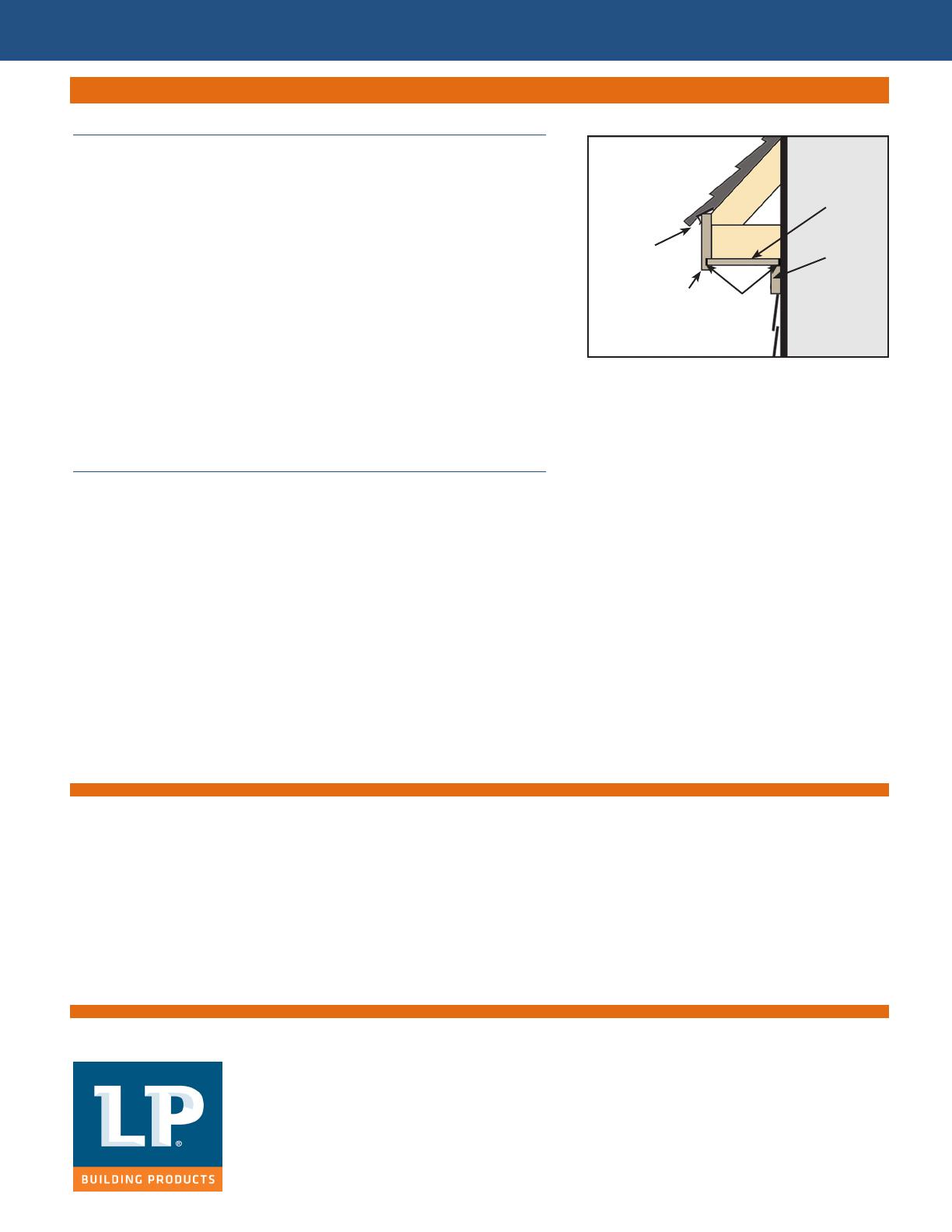
• Applying LP SmartSide Sot with LP SmartSide Ploughed Fascia
is approved for closed sot applications only. The ploughed
groove in the fascia receives the outside edge of the sot. You
must still maintain a minimum 3/16 inch space around all ends
and edges of the sot, and apply sealant. (See diagram 7a)
• Before installing be sure that the sot framing is straight, square
and level. Fasten the LP SmartSide Ploughed Fascia meeting the
specications in the LP SmartSide Trim and Fascia Application
Instructions.
• All panel ends and edges must be supported or backed by solid
support. Additional blocking may need to be installed.
GENERAL REQUIREMENTS (CONTINUED)
INSTALLATION
LP® SmartSide® Ploughed-Fascia with LP® SmartSide® Sot
7a
Drip-Edge
Ploughed-Fascia
3/16” Space
with Sealant
Sot
Trim
DO
• Prime all exposed wood substrates before painting.
• Paint all exposed sot surfaces.
• Thoroughly paint the bottom edges of sot especially all cut ends next to the roof line.
• Apply paint as soon as possible and within 180 days of application.
• Follow the coating manufacturer’s application and maintenance instructions.
Do Not Use:
• Semi-transparent stain.
• Shake and shingle paints.
• Vinyl-based resin formulas such as vinyl acetate, PVA, vinyl acetate/acrylic copolymer paints.
CAUTION:
HANDLE PREFINISHED LP SMARTSIDE PRODUCTS WITH EXTREME CARE DURING STORAGE AND APPLICATION.
TOUCH UP ANY DAMAGE TO THE FINISH THAT MAY OCCUR DURING APPLICATION PER PREFINISHERS SPECIFICATIONS.
GENERAL REQUIREMENTS (CONTINUED)
Finishing Instructions
Cal. Prop 65 Warning: Use of this product may result in exposure to
wood dust, known to the State of California to cause cancer.
Louisiana-Pacic Corporation
414 Union St.
Nashville, TN 37219
www.lpcorp.com
www.lpsmartside.com
© 2016 Louisiana-Pacic Corporation. All rights reserved. LP and
SmartSide are registered trademarks of Louisiana-Pacic
Corporation. Printed in U.S.A.
NOTICE: Louisiana-Pacic Corporation periodically updates and
revises its product information. The information in this document
is subject to change without notice. To verify that this version is
current, call 800-450-6106.
LPZB0519 4/16
LP SmartSide Sot
LIMITED WARRANTY
The Louisiana-Pacic Corporation (“LP”) LP® SmartSide® sot (the “Products”) limited warranty (the “Warranty”) applies only to
structures on which the Products have been applied, nished and maintained in accordance with the published application, nishing
and maintenance instructions in eect at the time of application. Products aected by a failure to follow such application, nishing or
maintenance instructions (“Aected Products”) will be excluded from coverage under the Warranty.
LP assumes no liability for any loss or damage caused by the Aected Products and is expressly released by the purchaser or
owner from any such loss or liability.
Any modication of the Warranty or the application, nishing and maintenance requirements is void unless approved in writing by LP prior
to application.
For a copy of the warranty or installation and technical support, visit the LP Web site at: www.lpcorp.com
WARRANTY REMEDIES ARE NOT AVAILABLE IF REQUIREMENTS ARE NOT FOLLOWED. or for additional support call 800-450-6106
7


