Page is loading ...

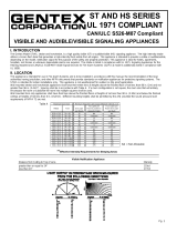
**Effective Intensity Requirements for Sleeping Area
Visible Notification Appliance
Distance from Ceiling to Top of Lens Intensity
greater than or equal to 24" (610mm) 110 Cd
less than 24" (610mm) 177 Cd
GXS REMOTE STROBE
UL 1971 COMPLIANT
Installation Instructions-Owner's Information
I. INTRODUCTION
The Gentex model GXS Remote Strobe is a high quality remote visible signaling appliance. The
high-intensity strobe utilizes a Xenon flash tube which generates a high-intensity light, visible
from all sides of the lens. The GXS Remote Strobe is intended to provide a visible notification
signal for the purpose of life safety and property protection. This appliance is ideal for hotels,
apartments, hospitals, rest homes or wherever dependable visible alarms are required. This
appliance is listed in compliance with UL 1971, Signaling Appliances For The Hearing Impaired.
II. LOCATION
This appliance is intended for use in Fire Alarm Systems and is to be installed in accordance with
this installation manual, the recommendation of the local authorities having jurisdiction, and other
NFPA Standards that provide standards on notification appliances for protective signaling
systems. The Gentex GXS Remote Strobe is intended for indoor installation only and is not
listed for outdoor or drip proof applications.
Wall-mounted appliances shall have their bottoms at heights above the finished floor of not less
than 80 in. (2m) and no greater than 96 in. (2.4m)**. Spacing shall be in accordance with Table
A. If a room configuration is not square, the room size that will entirely encompass the room or
subdivide the room into multiple squares shall be used.
WARNING! Visual signal must be in the direct viewing area of the occupant in order to be seen.
WARNING! Visual signal can not be seen when objects such as doors, furniture or walls block
visual signal.
NOTICE: Visual signals for the hearing impaired are only one method of alerting the hearing
impaired. Visual signals may not be the preferred method for notifying all hearing
impaired individuals.
For a period of 36 months from the date of purchase, or a maximum of
42 months from the date of manufacture, Gentex warrants to you, the
original purchaser, that your appliance will be free from defects in
workmanship, materials, and construction under normal use and
service. If a defect in workmanship, materials, or construction should
cause your appliance to become inoperable within the warranty period,
Gentex will repair your appliance or furnish you with a new or rebuilt
replacement appliance without charge to you except for postage required
to return the appliance to us. Gentex will not reimburse you for repairs or
replacement parts provided by other parties. Your repaired or replace-
ment appliance will be returned to you free of charge and it will be cov-
ered under this warranty for the balance of the warranty period.
This warranty is void if our inspection of your appliance shows that the
damage or failure was caused by abuse, misuse, abnormal usage, faulty
installation, improper maintenance, or repairs other than those performed
by us.
ANY WARRANTIES IMPLIED UNDER ANY STATE LAW,
INCLUDING IMPLIED WARRANTIES OF MERCHANTABILITY OR
FITNESS FOR A PARTICULAR PURPOSE, APPLY ONLY FOR THE
WARRANTY PERIOD SPECIFIED ABOVE. PLEASE NOTE THAT
SOME STATES DO NOT ALLOW LIMITATIONS ON HOW LONG AN
IMPLIED WARRANTY LASTS, SO THE ABOVE EXCLUSION MAY NOT
APPLY TO YOU.
GENTEX WILL NOT BE LIABLE FOR ANY LOSS, DAMAGE,
INCIDENTAL OR CONSEQUENTIAL DAMAGES OF ANY KIND
ARISING IN CONNECTION WITH THE SALE, USE OR REPAIR OF
THIS APPLIANCE. THE MAXIMUM LIABILITY OF GENTEX SHALL
NOT IN ANY CASE EXCEED THE PURCHASE PRICE PAID BY YOU
FOR THE APPLIANCE. PLEASE NOTE THAT SOME STATES DO NOT
ALLOW THE EXCLUSION OR LIMITATION OF INCIDENTAL OR CON-
SEQUENTIAL DAMAGES, SO THE ABOVE EXCLUSION MAY NOT
APPLY TO YOU.
If a defect in workmanship, materials, or construction should cause
your appliance to become inoperable within the warranty period, you
must return the appliance to Gentex postage prepaid. You must also
prove to the satisfaction of Gentex the date of purchase of your
appliance. Warranty service may only be performed by Gentex
personnel at Gentex's facilities in Zeeland, Michigan. You must also pack
the appliance to minimize the risk of it being damaged in transit. You
must also enclose a return address. Appliances returned for
warranty service should be sent to: Gentex Corporation, 10985 Chicago
Drive, Zeeland, MI 49464. If we receive an appliance in a damaged
condition as the result of shipping, we will notify you and you must file a
claim with the shipper.
THIS WARRANTY GIVES YOU SPECIFIC LEGAL RIGHTS AND YOU
MAY ALSO HAVE OTHER RIGHTS WHICH VARY FROM STATE TO
STATE.
GENTEX CORPORATION
10985 CHICAGO DRIVE, ZEELAND, MI 49464
PHONE: 800-436-8391
www.gentex.com
550-101-T
6-1-93
LIMITED WARRANTY
Note: AC Voltage Range Limits: 96-132v. This product was only tested to the stated voltage
range; do not apply 80% and 110% of this range for system operation.
NA = Not Allowable
Important Notice:
These materials have been prepared by Gentex Corporation ("Gentex") for informational purposes only, are necessarily summary, and are not purported to
serve as legal advice and should not be used as such. Gentex makes no representations and warranties, express or implied, that these materials are
complete and accurate, up-to-date, or in compliance with all relevant local, state and federal laws, regulations and rules. The materials do not address all
legal considerations as there is inevitable uncertainty regarding interpretation of laws, regulations and rules and the application of such laws, regulations
and rules to particular fact patterns. Each person's activities can differently affect the obligations that exist under applicable laws, regulations or rules.
Therefore, these materials should be used only for informational purposes and should not be used as a substitute for seeking professional legal advice.
Gentex will not be responsible for any action or failure to act in reliance upon the information contained in this material.
WARNING! Visual signal must be installed within 16 feet of the pillow when
used in a sleeping area.
REMOTE VISIBLE SIGNALING APPLIANCE
Table A
VI. CLEANING AND MAINTENANCE
Each notification signaling appliance should be maintained in reliable operating condition.
Periodic inspections and tests should be made to assure proper operation of the appliances.
Visible appliances may require periodic cleaning to remove dust or debris that may have
accumulated on the appliance. The frequency of cleaning will depend on the local ambient
conditions.
VII. TO RETURN A GXS REMOTE STROBE UNIT
Should you experience problems with your GXS Remote Strobe unit, proceed as follows.
1. Turn off electrical power to the auxiliary alarm circuit.
2. Unscrew the unit from the electrical box.
3. Disconnect the unit from the field wiring. Reconnect the two hot supply voltage circuits (black
wires) and the two neutral supply voltage circuits (white wires) for AC Models of the auxiliary
alarm circuit to maintain power to the other auxiliary alarm appliances in the system.
4. Carefully pack the defective unit (the manufacturer cannot be responsible for consequential
damage due to shipping or mishandling). Include your return address and complete details
as to the nature of the difficulties being experienced and date of installation.
5. Return to: Gentex Corporation, 10985 Chicago Drive, Zeeland, MI 49464. Prior to returning,
for a RMA number.
VIII. ELECTRICAL SPECIFICATIONS
WALL STROBE CURRENT RATINGS
Candela
Regulated 120VAC
Max. Operating Current(mA)
177 209
550-0101
Page 1
Room Spacing for Wall-Mounted Visible Appliances per NFPA 72, 2007 Edition
Maximum Room Size Minimum Required Light Output ( Effective Intensity, Cd)
Meters Feet
One Light per
Room
Two Lights per Room
(Located on Opposite Walls)
Four Lights per Room (One
Light per Wall)
6.10 x 6.10 20 x 20 15 NA NA
8.53 x 8.53 28 x 28 30 Unknown NA
9.14 x 9.14 30 x 30 34 15 NA
12.2 x 12.2 40 x 40 60 30 15
13.7 x 13.7 45 x 45 75 Unknown 19
15.2 x 15.2 50 x 50 94 60 30
16.5 x 16.5 54 x 54 110 Unknown 30
16.8 x 16.8 55 x 55 115 Unknown 28
18.3 x 18.3 60 x 60 135 95 30
19.2 x 19.2 63 x 63 150 Unknown 37
20.7 x 20.7 68 x 68 177 Unknown 43
21.3 x 21.3 70 x 70 184 95 60
24.4 x 24.4 80 x 80 240 135 60
27.4 x 27.4 90 x 90 304 185 95
30.5 x 30.5 100 x 100 375 240 95
33.5 x 33.5 110 x 110 455 240 135
36.6 x 36.6 120 x 120 540 305 135
39.6 x 39.6 130 x 130 635 375 185
Page 4
THIS APPLIANCE WILL NOT OPERATE WITHOUT ELECTRICAL POWER. AS FIRES
FREQUENTLY CAUSE POWER INTERRUPTIONS, GENTEX SUGGESTS YOU DISCUSS
FURTHER SAFEGUARDS WITH YOUR LOCAL FIRE PROTECTION SPECIALIST.

III. MOUNTING ROUGH-IN BOX AND RUN WIRING
The GXS Remote Strobe is designed for mounting to most single and double gang electrical
boxes. Conduit entrance to boxes should be selected to insure sufficient wiring clearance.
1. Mount a box for each remote signaling device.
2. Run a minimum 16-gauge insulated, 2-conductor cable for AC strobes.
NOTICE: All visual signals are designed to flash as specified with continuous applied
voltage. This appliance is not recommended for use on coded or pulsing
signaling circuit.
IV. MOUNT ADAPTER PLATE, CONNECT WIRES AND INSTALL UNIT
Depending on the type of electrical box installed, the GXS Remote Strobe unit can be mounted
directly to the box, or by using the mounting adapter plate provided. (See Figures A and B.)
1. If needed, secure the mounting adapter plate to the electrical box. Use screws provided with
electrical box. IMPORTANT: Mounting plate is marked "THIS SIDE OUT" and slotted for
proper positioning.
2. The GXS Remote Strobe has two terminals for power-in and power-out supply circuits. For
each terminal, one is for the incoming circuit and one is for the outgoing circuit.
3. Make wire connections as follows: hot to + and neutral to - for AC models.
4. Secure the GXS Remote Strobe to the electrical box with two of the screws provided.
Use the longer screws for direct mounting and the shorter screws for attachment to the
mounting plate.
CAUTION
WHEN INSTALLING, ROUTE FIELD WIRING AWAY FROM SHARP PROJECTIONS,
CORNERS AND INTERNAL COMPONENTS.
FIG. A
FIG. B
FAILURE TO OBSERVE ANY OF THE CONDITIONS SET FORTH MAY CAUSE
MALFUNCTION AND DAMAGE TO THE APPLIANCE.
V. CHECKOUT AND TROUBLESHOOTING
1. Supply power to the system control panel. The auxiliary signaling appliances in the system
should not be activated.
2. If the signal is activated:
a. Check all smoke alarms and fire detectors in the system to make sure they have not been
activated.
b. Check all wiring connections to make sure the signal detection circuits are not reversed or
shorted together. Check wire color codes and traces.
3. To test the GXS Remote Strobe and other signaling appliances, trip the auxiliary panel or
activate alarm circuit at the main control panel or activate one of the fire detection units in the
system. All auxiliary signals should be activated.
4. An operational test on this product should be conducted in accordance with National
Standards or at a minimum annually and more often if dictated by local and state codes or
authorities having jurisdiction.
NOTE: These testing and troubleshooting instructions are generalized. Please refer to
the system control panel operating instructions for proper operation of the panel and fire
detection system.
WARNING! Visual signal must be installed within 16 feet of the pillow when used in a
sleeping area.
WARNING! Visual signal must be in the direct viewing area of the occupant in order to be seen.
WARNING! Visual signal can not be seen when objects such as doors, furniture or walls
block visual signal.
NOTICE: Visual signals for the hearing impaired are only one method of alerting the hearing
impaired. Visual signals may not be the preferred method for notifying all hearing
impaired individuals.
NOTICE: The visual signal must be seen by the sleeping person. If the person has head
turned or otherwise unable to be alerted by visual, the visual signal will not be
effective.
Visual Signal should NEVER be relied upon as the primary fire alert for the
hearing impaired under these common sense conditions:
a. Sleeping face down on the bedding or pillow
b. Use of sleep medications of any kind
c. Use of alcoholic beverages or recreational drugs
d. Use of eye shades
e. If there are tendencies of deep sleep conditions
f. If a fire cuts power to AC circuits, the visual signal will not operate.
g. If person is not within line of sight of visual signals
Under these and other similar common situations an alternate fire alert method such
as a non-hearing impaired attendant is needed. The visual signal only increases the
chance of being alerted to the presence of fire. No system of this type can fully protect
the hearing impaired in case of fire.
550-0101
Page 3
550-0101
Page 2
/