Helios Large Display Analog Input Batch Controller
Instruction Manual PD2-6210
Precision Digital Corporation
233 South Street • Hopkinton MA 01748 USA
Tel (800) 343-1001 • Fax (508) 655-8990
www.predig.com
Batch Controller
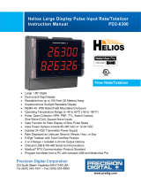
• Large 1.80" Digits
• Dual-Line 6-Digit Display
• Readable from up to 100 Feet (30 Meters) Away
• Superluminous Sunlight Readable Display
• NEMA 4X, IP65 Rated Field Mountable Enclosure
• Operating Temperature Range of -40 to 65°C (-40 to 150°F)
• Single or Multi-Stage Batch Control (up to 4 Relays)
• 0-20 mA, 4-20 mA, 0-5 V, 1-5 V, and ±10 V Inputs
• Input Power Options Include 85-265 VAC or 12-24 VDC
• Isolated 24 VDC Transmitter Power Supply
• Start/Pause/Stop, Change Batch with Front Panel Buttons
• Automatic Overrun Correction
• Count Up or Down with Each Batch
• 2 or 4 Relays + Isolated 4-20 mA Output Options
• Onboard USB & RS-485 Serial Communications
• Modbus
®
RTU Communication Protocol Standard
• Program the Meter from a PC with onboard USB and MeterView Pro
USB Install

Helios Large Display Analog Input Batch Controller Instruction Manual PD2-6210
2
Disclaimer
The information contained in this document is subject to change without notice. Precision
Digital makes no representations or warranties with respect to the contents hereof and
specifically disclaims any implied warranties of merchantability or fitness for a particular
purpose.
Caution: Read complete
instructions prior to installation and
operation of the controller.
Warning: Risk of electric shock or
personal injury.
Warning!
This product is not recommended for life support
applications or applications where malfunctioning
could result in personal injury or property loss. Anyone
using this product for such applications does so at their
own risk. Precision Digital Corporation shall not be held
liable for damages resulting from such improper use.
Limited Warranty
Precision Digital Corporation warrants this product against defects in material or
workmanship for the specified period under “Specifications” from the date of shipment from
the factory. Precision Digital’s liability under this limited warranty shall not exceed the
purchase value, repair, or replacement of the defective unit.
Registered Trademarks
MeterView
®
Pro is a registered trademark of Precision Digital Corporation. All other
trademarks mentioned in this document are the property of their respective owners.
© 2018 Precision Digital Corporation. All rights reserved.
www.predig.com
!

PD2-6210 Helios Large Display Analog Input Batch Controller Instruction Manual
3
Table of Contents
Table of Contents .................................................... 3
Table of Figures ...................................................... 4
Introduction.............................................................. 4
Ordering Information ............................................... 5
Specifications .......................................................... 5
General ....................................................................... 5
Process Input .............................................................. 6
Batch Controller Rate/Totalizer Display ...................... 6
Relays ......................................................................... 7
Isolated 4-20 mA Transmitter Output .......................... 7
RS485 Serial Communications Terminal .................... 8
Modbus
®
RTU Serial Communications........................ 8
Digital Input & Output Terminal ................................... 8
Compliance Information .......................................... 9
Safety .......................................................................... 9
Safety Information .................................................10
Installation .............................................................10
Unpacking ................................................................. 10
Wall Mounting Instructions ........................................ 11
Pipe Mounting Instructions ........................................ 12
Transmitter Supply Voltage Selection (P+, P-) .......... 13
Connections .............................................................. 13
Connectors Labeling ............................................. 14
Power Connections ............................................... 14
Signal Connections ............................................... 15
Modbus RTU Serial Communications ................... 16
Relay Connections ................................................ 16
Switching Inductive Loads ..................................... 17
RS485 Output Connections................................... 18
Digital I/O Connections ......................................... 20
F4 Digital Input Connections ................................. 20
4-20 mA Output Connections ................................ 21
Analog Output Transmitter Power Supply ............. 21
Interlock Relay Feature ......................................... 21
Basic Operation and Programming .......................22
Overview ................................................................... 22
Programming Buttons and Status LED Indicators ..... 23
MeterView
®
Pro Software .......................................... 24
MeterView Pro Installation..................................... 24
Controller Operation .................................................. 25
Default Batch Control Operation ........................... 25
Batch Control Operation Example ......................... 26
Display Functions & Messages ................................. 28
Main Menu ................................................................ 31
Setting Numeric Values ............................................. 31
Setting up the Batch Controller (setup) .................... 32
Setting the Input Signal (Input) ............................ 32
Setting the Totalizer and Batching Features (total)
.............................................................................. 32
Setting the Input Units or Custom Tags (units) ... 33
Setting the Decimal Point (dEc pt) ....................... 33
Programming the Batch Controller (prog) ............. 34
Setting the Display Parameter & Intensity (dsplay)
.............................................................................. 38
Setting the Relay Operation (relay) ......................... 39
Relay Assignment (Assign) .................................. 40
Setting the Relay Action ........................................ 40
Setting Batch Control Relays ................................. 40
Programming Set and Reset Points ...................... 41
Setting Fail-Safe Operation ................................... 41
Programming Time Delay ...................................... 41
Relay Action for Loss of 4-20 mA Input (Loop Break)
.............................................................................. 41
Relay and Alarm Operation Diagrams ....................... 42
High Alarm Operation (Set > Reset) ...................... 42
Low Alarm Operation (Set < Reset) ....................... 42
High Alarm with Fail-Safe Operation (Set > Reset)42
Low Alarm with Fail-Safe Operation (Set < Reset) 42
Relay Sampling Operation ..................................... 42
Total Relay Sampling Operation ............................ 43
Signal Loss or Loop Break Relay Operation .......... 43
Time Delay Operation ............................................ 43
Relay Operation Details ............................................. 44
Overview ............................................................... 44
Relays Initialization ................................................ 44
Fail-Safe Operation ............................................... 44
Front Panel LEDs .................................................. 44
Automatic Reset (Auto) ......................................... 45
Pump Alternation Control Applications (Altern) ... 45
Setting up the Interlock Relay (Force On) Feature 45
Sample Relay Operation ....................................... 46
Scaling the 4-20 mA Analog Output (Aout) ............... 46
Reset Menu (reset) .................................................. 46
Control Menu (Contrl) .............................................. 46
Setting up the Password (pass) ................................ 47
Protecting or Locking the Meter ............................. 47
Total Reset Password & Non-Resettable Total ..... 47
Making Changes to a Password Protected Meter.. 48
Disabling Password Protection .............................. 48
Advanced Operation and Programming ............... 49
Function Keys Operation ........................................... 49
Digital Input Operation ........................................... 49
Advanced Setup and Calibration ............................... 49
Multi-Point Calibration & Scaling ........................... 49
Maximum/Minimum Readings ................................... 49
Advanced Features Menu ......................................... 50
Advanced Features Menu & Display Messages .... 50
Noise Filter (filter) ............................................. 52
Noise Filter Bypass (bypass) ................................ 52
Rounding Feature (round) ..................................... 52
Modbus RTU Serial Communications (serial) .... 52
Select Menu (SElect) ........................................... 53
Signal Input Conditioning (Functn) ....................... 53
Low-Flow Cutoff (CutofF) ..................................... 54
Total and Grand Total Count Direction (Count) ..... 54
Analog Output Programming (AoutPr) .................. 54
Programmable Function Keys User Menu (user) .. 54
Internal Source Calibration (ICAL) ......................... 56
Troubleshooting .................................................... 57
Diagnostics Menu (diag) ........................................... 57
Determining Software Version ............................... 57
Reset Controller to Factory Defaults .......................... 57
Factory Defaults & User Settings........................... 58
Troubleshooting Tips ................................................. 60

Helios Large Display Analog Input Batch Controller Instruction Manual PD2-6210
4
Table of Figures
Figure 1. Meter Mounting Holes ............................11
Figure 2. Controller Dimensions - Side View ........11
Figure 3. Controller Dimensions – Front View ......11
Figure 4. Vertical Pipe Mount Assembly ...............12
Figure 5. Horizontal Pipe Mount Assembly ...........12
Figure 6. Transmitter Supply Voltage Selection....13
Figure 7. Connector Labeling for Fully Loaded PD2-
6210 ......................................................................14
Figure 8. Power Connections ................................14
Figure 9. Transmitters Powered by Internal Supply
..............................................................................15
Figure 10. Transmitter Powered by Ext. Supply or
Self-Powered .........................................................15
Figure 11. Voltage Input Connections .................. 16
Figure 12. Relay Connections .............................. 16
Figure 13. AC and DC Loads Protection .............. 17
Figure 14. Low Voltage DC Loads Protection ...... 17
Figure 15. RS-422 or RS-485 Wiring .................... 18
Figure 16. RS-485 Two-Wire Multi-Drop Wiring ... 19
Figure 17. Connections for RS485 Connector to
Serial Converter .................................................... 19
Figure 18. Three-Wire RS485 Connection ........... 19
Figure 19. Digital Input and Output Connections . 20
Figure 20. F4 Digital Input Connections ............... 20
Figure 21. 4-20 mA Output Connections .............. 21
Figure 22. Interlock Connections .......................... 21
Introduction
The Helios PD2-6210 is a multi-purpose, easy to use, large-display batch controller ideal for
simplifying independent batch control operations where local control is preferred to expensive
and expansive plant operation systems. It features large 1.8 superluminous inch LED digits,
which can be read in sunlight from up to 100 feet away. It is housed in a water-resistant, field
mountable NEMA 4X/IP65 rated enclosure for convenient indoor and outdoor installation.
The controller comes programmed for easy start, pause, stop, and batch size (preset) changes.
Display line two (2) can be programmed to display rate, grand total, batch count, or preset by
cycling the Stop (F3) button. Digital inputs come standard.
Single and multi-stage batching is possible with up to four (4) on-board relays. Each batch
control relay may have a unique preclose amount when used for multi-stage batching. Manual
start batching is default, but automatic batching with a restart after a programmed time delay
from the completion of the last batch is also possible.
Overrun correction adjusts the closing of the batch control relays to adjust for inaccuracies from
batch to batch. This increases accuracy over time as systems wear out. The overrun correction
feature is capable of compensating for inaccuracies of up to 10% of the programmed preset
value.
The controller accepts current and voltage signals (e.g. 4-20 mA, 0-10 V). Three of the
programming buttons can be set for custom operation. A fully loaded PD2-6210 batch controller
comes with four (4) SPDT relays, a 4 20 mA output, two 24 VDC power supplies, five (5) digital
inputs and four (4) digital outputs, and RS485 serial communications, making it an excellent
addition to any system.

PD2-6210 Helios Large Display Analog Input Batch Controller Instruction Manual
5
Ordering Information
Standard Models
85-265 VAC Model
12-24 VDC Model
Options Installed
PD2-6210-6H2
PD2-6210-7H2
2 Relays
PD2-6210-6H7
PD2-6210-7H7
4 relays & 4-20 mA output
Accessories
Model
Description
PDA6260
Pipe Mounting Kit
PDA7485-I
RS-232 to RS-422/485 isolated converter
PDA7485-N
RS-232 to RS-422/485 non-isolated converter
PDAPLUG2
Plastic Conduit Plug
PDX6901
Suppressor (snubber): 0.01 µF/470 , 250 VAC
Specifications
Except where noted all specifications apply to operation at +25°C.
General
Display
Main display: 1.8" (46 mm) high,
red LEDs
6 digits per line (-99999 to
999999), with lead zero blanking
Display
Intensity
Eight user selectable intensity
levels
Display
Update Rate
5/second (200 ms)
Overrange
Display flashes 999999
Underrange
Display flashes -99999
Display
Assignment
Display lines 1 & 2 may be
assigned to rate, total, grand total,
batch count, preset, set points,
units (lower display only),
alternating R & T, R & GT, preset
& rate, max & min, or a Modbus
display register. Any
rate/total/grand total display may
be programmed to alternate with a
custom unit or tag.
Alternating
Display
Displays alternate every 10
seconds when display is selected
or batch is paused.
Programming
Methods
Four programming buttons, digital
inputs, PC and MeterView Pro
software, or Modbus registers.
Noise Filter
Programmable from 2 to 199 (0 will
disable filter)
Filter Bypass
Programmable from 0.1 to 99.9%
of calibrated span
Recalibration
All ranges are calibrated at the
factory. Recalibration is
recommended at least every
12 months.
Max/Min
Display
Max/min readings reached by the
process are stored until reset by
the user or until power to the
controller is turned off.
Password
Three programmable passwords
restrict modification of
programmed settings.
Pass 1: Allows use of function
keys and digital inputs
Pass 2: Allows use of function
keys, digital inputs and editing
set/reset points
Pass 3: Restricts all programming,
function keys, and digital inputs
Total: Prevents resetting the total
manually
Gtotal: Prevents resetting the
grand total manually.
Power Options
85-265 VAC 50/60 Hz, 90-265
VDC, 20 W max or 12-24 VDC
10%, 15 W max
Powered over USB for configuration
only.
Isolated
Transmitter
Power Supply
Terminals P+ & P-: 24 VDC 10%.
12-24 VDC powered models
selectable for 24, 10, or 5 VDC supply
(internal P+/P- switch).
85-265 VAC models rated @ 200 mA
max, 12-24 VDC powered models
rated @ 100 mA max, @ 50 mA max
for 5 or 10 VDC supply.
Non-Volatile
Memory
All programmed settings are stored
in non-volatile memory for a
minimum of ten years if power is
lost.

Helios Large Display Analog Input Batch Controller Instruction Manual PD2-6210
6
Fuse
Required external fuse: UL
Recognized, 5 A max, slow blow;
up to 6 controllers may share one
5 A fuse
Normal Mode
Rejection
Greater than 60 dB at 50/60 Hz
Isolation
4 kV input/output-to-power line;
500 V input-to-output or output-to-
P+ supply
Overvoltage
Category
Installation Overvoltage Category
II:
Local level with smaller transient
overvoltages than Installation
Overvoltage Category III.
Environmental
Operating temperature range: -40
to 150°F (-40 to 65°C)
Storage temperature range: -40 to
185°F (-40 to 85°C)
Relative humidity: 0 to 90% non-
condensing
Connections
Removable and integrated screw
terminal blocks accept 12 to 22
AWG wire.
Enclosure
UL Type 4X, IP65 rated.
Polycarbonate & glass blended
plastic case, color: gray. Includes
four PG11 through-hole conduit
openings, with two factory installed
PG11, IP68, black nylon threaded
hole plugs with backing nuts.
Mounting
Wall Mounting: Four (4) mounting
holes provided for screwing
controller into wall. See Wall
Mounting Instructions on page 11
for additional details.
Pipe Mounting: Optional pipe
mounting kit (PDA6260) allows for
pipe mounting. Sold separately.
See Pipe Mounting Instructions on
page 12 for additional details.
Tightening
Torque
Removable Screw Terminals: 5
lb-in (0.56 Nm)
Digital I/O and RS485 Terminals:
2.2 lb-in (0.25 Nm)
Overall
Dimensions
10.63" x 12.59" x 4.77" (270 mm x
319.7 mm x 121.2 mm) (W x H x
D)
Weight
6.10 lbs (2.76 kg)
Warranty
3 years parts & labor
Process Input
Inputs
Field selectable: 0-20, 4-20 mA,
10 V (0-5, 1-5, 0-10 V), Modbus
PV (Slave)
Accuracy
±0.03% of calibrated span ±1
count,
square root & programmable
exponent accuracy
range: 10-100% of calibrated span
Temperature
Drift
0.005% of calibrated span/C max
from 0 to 65C ambient,
0.01% of calibrated span/C max
from -40 to 0C ambient
Signal Input
Conditioning
Linear, square root, programmable
exponent, or round horizontal tank
volume calculation
Multi-Point
Linearization
2 to 32 points
Programmable
Exponent
1.0001 to 2.9999
Round H Tank
Diameter & Length: 999.999 inch
or cm calculates volume in gallons
or liters respectively.
Low-Flow Cutoff
0-999999 (0 disables cutoff
function)
Decimal Point
Up to five decimal places or none:
d.ddddd, d.dddd, d.ddd, d.dd, d.d,
or dddddd
Calibration
Range
Input Range
Minimum Span Input
1 & Input 2
4-20 mA
0.15 mA
10 V
0.01 V
An error message will appear if the
input 1 and input 2 signals are too
close together.
Input Impedance
Voltage ranges: greater than 500
k
Current ranges: 50 - 100
(depending on resettable fuse
impedance)
Input Overload
Current input protected by
resettable fuse, 30 VDC max.
Fuse resets automatically after
fault is removed.
F4 Digital Input
Contacts
3.3 VDC on contact. Connect
normally open contacts across F4
to COM.
F4 Digital Input
Logic Levels
Logic High: 3 to 5 VDC; Logic
Low: 0 to 1.25 VDC
Batch Controller Rate/Totalizer Display
Rate Display
Indication
-99999 to 999999, lead zero
blanking. “R” LED illuminates while
displaying rate.
Batch Total &
Grand Total
Display
0 to 999,999; automatic lead zero
blanking. “T” LED is illuminated
while displaying batch total. “GT”
LEDs are illuminated while
displaying grand total. Up to
999,999 for batch total/preset. Up to
999,999,999 with grand total-
overflow feature. “oF” is displayed
to the left of grand total overflow
and ▲ LED is illuminated.
Batch Total
Decimal Point
Up to five decimal places or none:
d.ddddd, d.dddd, d.ddd, d.dd, d.d,
or dddddd
Total decimal point is independent
of rate decimal point.

PD2-6210 Helios Large Display Analog Input Batch Controller Instruction Manual
7
Totalizer
Calculates total based on rate and
field programmable multiplier to
display total in engineering units.
Time base must be selected
according to the time units in which
the rate is displayed.
Grand Totalizer
Rollover
Grand totalizer rolls over when
display exceeds 999,999,999.
Relay status reflects display.
Grand Total
Alarms
Up to seven, user selectable under
setup menu. Any set point can be
assigned to grand total and may
be programmed anywhere in the
range of the controller for grand
total alarm indication. Relay 1
should always be assigned to
batch.
Programmable
Delay
On Release
0.1 and 999.9 seconds; applied to
the first relay assigned to total or
grand total.
If the controller is programmed to
reset total to zero automatically
when the preset is reached, then a
delay will occur before the total is
reset.
Grand Total
Reset
Via front panel button, external
contact closure on digital inputs,
automatically via user selectable
preset value and time delay, or
through serial communications.
Grand Total
Reset Password
Grand total passwords may be
entered to prevent resetting the
grand total from the front panel.
Non-Resettable
Grand Total
The grand total can be
programmed as a non-resettable
total by entering the password
“050873”.
Caution!
Once the Grand Total
has been programmed
as “non-resettable” the
feature cannot be
disabled.
Relays
Rating
2 or 4 SPDT (Form C) internal
and/or 4 SPST (Form A) external;
rated 3 A @ 30 VDC and 125/250
VAC resistive load; 1/14 HP (≈ 50
W) @ 125/250 VAC for inductive
loads
Noise
Suppression
Noise suppression is
recommended for each relay
contact switching inductive loads;
see page 17 for details.
Deadband
0-100% of span, user
programmable
1
Alarms are active only when the batch is running.
High or Low
Alarm
User may program any alarm for
high or low trip point.
Unused alarm LEDs and relays
may be disabled (turn off).
Relay Operation
Primary Functions:
Batch Control
Automatic (non-latching)
1
Sampling (based on time)
Off (disable unused relays and
enable Interlock feature)
Manual on/off control mode
Secondary Functions
2
:
Pump alternation control (2 to 4
relays)
Latching (requires manual
acknowledge)
Relay Reset
User selectable via front panel
buttons or digital inputs
1. Automatic reset only (non-
latching), when the input
passes the reset point.
2. Automatic + manual reset at
any time (non-latching)
3. Manual reset only, at any time
(latching)
4. Manual reset only after alarm
condition has cleared (latching)
Note: Front panel button or digital
input may be assigned to
acknowledge relays
programmed for manual
reset.
Alarm Time
Delay
0 to 999.9 seconds, on & off relay
time delays
Programmable and independent
for each relay
Fail-Safe
Operation
Programmable and independent
for each relay.
Note: Relay coil is energized in
non-alarm condition. In case
of power failure, relay will go
to alarm state.
Alarm Auto
Initialization
When power is applied to the
controller, relays will reflect the
state of the input to the controller.
Isolated 4-20 mA Transmitter Output
Output Source
Process variable (PV), max, min,
set points 1-8, Modbus input, or
manual control mode
Scaling Range
1.000 to 23.000 mA for any display
range
Calibration
Factory calibrated: 4.000 to 20.000
= 4-20 mA output
Analog Out
Programming
23.000 mA maximum for all
parameters:
Overrange, underrange, max, min,
and break
Accuracy
± 0.1% of span ± 0.004 mA
2
These operations are not functional when the unit is
being used as a batch controller with total set to yes.
!

Helios Large Display Analog Input Batch Controller Instruction Manual PD2-6210
8
Temperature
Drift
0.4 µA/C max from 0 to 65C
ambient,
0.8 µA/C max from -40 to 0C
ambient
Note: Analog output drift is
separate from input drift.
Isolated
Transmitter
Power Supply
Terminals I+ & R: 24 VDC 10%.
May be used to power the 4-20 mA
output or other devices. Refer to
Figure 21 on page 21.
All models rated @ 40 mA max.
External Loop
Power Supply
35 VDC maximum
Output Loop
Resistance
Power supply
Minimum
Maxi
mum
24 VDC
10
700
35 VDC
(external)
100
1200
RS485 Serial Communications Terminal
Compatibility
EIA-485
Connectors
Removable screw terminal
connector
Max Distance
3,937' (1,200 m) max
Status Indication
Separate LEDs for Power (P),
Transmit (TX), and Receive (RX)
Modbus
®
RTU Serial Communications
Slave Id
1 – 247 (Controller address)
Baud Rate
300 – 19,200 bps
Transmit Time
Delay
Programmable between 0 and 199
ms
Data
8 bit (1 start bit, 1 or 2 stop bits)
Parity
Even, Odd, or None with 1 or 2
stop bits
Byte-To-Byte
Timeout
0.01 – 2.54 second
Turn Around
Delay
Less than 2 ms (fixed)
Note: Refer to the Modbus Register Tables located at
www.predig.com for details.
Digital Input & Output Terminal
Channels
4 digital inputs & 4 digital outputs
Digital Input
Logic High
3 to 5 VDC
Digital Input
Logic Low
0 to 1.25 VDC
Digital Output
Logic High
3.1 to 3.3 VDC
Digital Output
Logic Low
0 to 0.4 VDC
Source Current
10 mA maximum output current
Sink Current
1.5 mA minimum input current
+5 V Terminal
To be used as pull-up for digital
inputs only.
Connect normally open
pushbuttons across +5 V & DI 1-4.
Warning!
DO NOT use
+5 V terminal
to power
external
devices.

PD2-6210 Helios Large Display Analog Input Batch Controller Instruction Manual
9
Compliance Information
Safety
UL & C-UL Listed
USA & Canada
UL 508 Industrial Control Equipment (United States),
C22.2 No. 142 (Canadian National Standard)
UL File Number
E160849
Front Panel
UL Type 4X, NEMA 4X, IP65
Low Voltage Directive
EN 61010-1:2010
Safety requirements for measurement, control, and laboratory use

Helios Large Display Analog Input Batch Controller Instruction Manual PD2-6210
10
Safety Information
Caution: Read complete instructions
prior to installation and operation of the
controller.
Warning: Risk of electric shock or
personal injury.
Warning!
Hazardous voltages exist within enclosure.
Installation and service should be performed only by trained
service personnel.
Installation
There is no need to open the clear plastic front cover in order to complete the installation, wiring,
and setup of the controller. All programming is done through the buttons and switches located
under the lower door panel and are accessible by removing the single securing screw. Wires
should be run through the knockout holes located on the bottom of the controller.
There are a total of four pre-drilled conduit entry holes located at the bottom of the controller. If
the need to drill additional holes arises, make sure you will have the clearance necessary for
conduit mounting hardware.
Do not disconnect the RJ45 connector found on the right side of the controller wiring board. Doing
so will disable the onboard digital I/O, RS-485 serial communications, and M-Link functionality.
Instructions are provided for changing the transmitter power supply to output 5 or 10 VDC instead
of 24 VDC, see page 12.
Unpacking
Remove the controller from box. Inspect the packaging and contents for damage. Report
damages, if any, to the carrier. If any part is missing or the controller malfunctions, please contact
your supplier or the factory for assistance.
!

PD2-6210 Helios Large Display Analog Input Batch Controller Instruction Manual
11
Wall Mounting Instructions
The meter can be mounted to any wall using the four provided mounting holes. Note that the bottom
mounting holes are located underneath the front door panel. To mount the meter to a wall, follow these
instructions.
1. Prepare a section of wall
approximately 11” x 13” (280 mm x
330 mm) for controller mounting by
marking with a pencil the mounting
holes (shown in the image to the
right) on the wall.
2. Using a drill bit slightly smaller than
the girth of the mounting screws,
pre-drill holes at the mounting
locations previously marked.
3. Insert mounting screws into the four
mounting holes and screw them into
the pre-drilled holes. Do not
overtighten the mounting screws
as it is possible that the enclosure
could crack and become damaged.
Figure 1. Meter Mounting Holes
Mounting Dimensions
Figure 2. Controller
Dimensions - Side View
Figure 3. Controller Dimensions – Front View
2. 63" (67 mm)
4. 77"
(121. 2 mm)
Mounting Hole Mounting Hole
Front Door
Panel Screw
10.63" (270 mm)
12.59" (319.7 mm)
10.43" (265 mm)
9.8" (249 mm)
11.14" (283 mm)

Helios Large Display Analog Input Batch Controller Instruction Manual PD2-6210
12
Pipe Mounting Instructions
The meter can also be mounted to a pipe using the optional pipe mounting kit (PDA6260). This kit
includes two mounting plates, two U-bolts, and the necessary nuts and bolts. To mount the meter to a
pipe using the pipe mounting kit accessory, follow these instructions.
1. Secure the mounting plates to the top
and bottom (for vertical pipes) or left and
right (for horizontal pipes) of the reverse
side of the meter enclosure using the
provided fasteners. Do not overtighten
the fasteners as it could cause damage
to the enclosure.
2. Using the provided nuts and U-bolts,
secure the mounting plates to the pipe
enough torque such that the meter
cannot be moved up or down (or side to
side).
Figure 4. Vertical Pipe Mount Assembly
Figure 5. Horizontal Pipe Mount Assembly

PD2-6210 Helios Large Display Analog Input Batch Controller Instruction Manual
13
Transmitter Supply Voltage Selection (P+, P-)
All meters, including models equipped with the 12-24 VDC power option, are shipped from the factory
configured to provide 24 VDC power for the transmitter or sensor.
If the transmitter requires 5 or 10 VDC excitation, the switch labeled P+/P- must be configured
accordingly.
To access the voltage selection jumper:
1. Unplug the meter power.
2. Unscrew and open the front door panel.
3. Locate the P+/P- switch located in the center of the connections board (see diagram below).
4. Flip this switch into the appropriate position for the required transmitter excitation.
Figure 6. Transmitter Supply Voltage Selection
Connections
All connections are made to screw terminal connectors located under the front door panel. Remove the
single securing screw in order to access the wiring terminals.
Caution
Use copper wire with 60°C or 60/75°C
insulation for all line voltage connections.
Observe all safety regulations. Electrical
wiring should be performed in accordance
with all applicable national, state, and local
codes to prevent damage to the meter and
ensure personnel safety.
MENU START
F1
BATCH
F2
STOP
F3

Helios Large Display Analog Input Batch Controller Instruction Manual PD2-6210
14
Connectors Labeling
The connectors’ label, affixed to the inside of the lower door panel, shows the location of all connectors
available with requested configuration.
Warning!
Do not connect any equipment other than Precision Digital’s
expansion modules, cables, or meters to the RJ45 M-LINK connector.
Otherwise damage will occur to the equipment and the meter.
Do not disconnect the RJ45 connector located to the left of the power
terminal block. Doing so will disable the onboard digital I/O, RS-485
serial communications, and M-Link functionality.
Figure 7. Connector Labeling for Fully Loaded PD2-6210
Power Connections
Power connections are made to a two-terminal connector labeled POWER on Figure 7 on page 14. The
meter will operate regardless of DC polarity connection. The + and - symbols are only a suggested wiring
convention.
Figure 8. Power Connections
MENU START
F1
BATCH
F2
STOP
F3
MA OUT
21 3
43 6521
RELAY4RELAY3
43 6521
RELAY2RELAY1
AC or DC
POWER
Required External Fuse:
5 A max, 250 V Slow Blow
POWER
+
-

PD2-6210 Helios Large Display Analog Input Batch Controller Instruction Manual
15
Signal Connections
Signal connections are made to a six-terminal connector labeled SIGNAL on Figure 7. The COM
(common) terminal is the return for the 4-20 mA and the 10 V input signals.
Current and Voltage Connections
The following figures show examples of current and voltage connections.
There are no switches or jumpers to set up for current and voltage inputs. Setup and programming is
performed through the front panel buttons.
Figure 9. Transmitters Powered by Internal Supply
Figure 10. Transmitter Powered by Ext. Supply or Self-Powered
The current input is protected against current overload by a resettable fuse. The display may or may not
show a fault condition depending on the nature of the overload.
The fuse limits the current to a safe level when it detects a fault condition, and automatically resets itself
when the fault condition is removed.

Helios Large Display Analog Input Batch Controller Instruction Manual PD2-6210
16
Figure 11. Voltage Input Connections
The meter is capable of accepting any voltage from -10 VDC to +10 VDC.
Modbus RTU Serial Communications
Serial communications connection can be made to the onboard RS485 terminal block or USB connector
shown in Figure 7. If RS232 is required, an RS485 to RS232 adapter (PDA7485) may be used. See
Ordering Information on page 5 for additional information.
Relay Connections
Relay connections are made to two six-terminal connectors labeled
RELAY1 – RELAY4 on Figure 7. Each relay’s C terminal is common only to the normally open (NO) and
normally closed (NC) contacts of the corresponding relay. The relays’ C terminals should not be confused
with the COM (common) terminal of the INPUT SIGNAL connector.
Figure 12. Relay Connections
-+
+
Voltage
Signal
mA+P-
21 3 54
P+ V+
COM
INPUT SIGNAL
mA+P-
21 3 54
P+ V+
COM
INPUT SIGNAL
3-Wire Voltage
Transducer
Signal
-
43 6521
RELAY4RELAY3
43 6521
RELAY2RELAY1

PD2-6210 Helios Large Display Analog Input Batch Controller Instruction Manual
17
Switching Inductive Loads
The use of suppressors (snubbers) is strongly recommended when switching inductive loads to prevent
disrupting the microprocessor’s operation. The suppressors also prolong the life of the relay contacts.
Suppression can be obtained with resistor-capacitor (RC) networks assembled by the user or purchased
as complete assemblies. Refer to the following circuits for RC network assembly and installation:
Figure 13. AC and DC Loads Protection
Choose R and C as follows:
R: 0.5 to 1 Ω for each volt across the contacts
C: 0.5 to 1 µF for each amp through closed contacts
Notes:
1. Use capacitors rated for 250 VAC.
2. RC networks may affect load release time of solenoid loads. Check to confirm proper operation.
3. Install the RC network at the meter's relay screw terminals. An RC network may also be installed
across the load. Experiment for best results.
Figure 14. Low Voltage DC Loads Protection
RC Networks Available from Precision Digital
RC networks are available from Precision Digital and should be applied to each relay contact switching an
inductive load. Part number: PDX6901.
Note: Relays are de-rated to 1/14th HP (50 watts) with an inductive load.
C
R
C
R
Use a diode with a
reverse breakdown
voltage two to three
times the circuit
voltage and forward
current at least as
large as the load
current.

Helios Large Display Analog Input Batch Controller Instruction Manual PD2-6210
18
RS485 Output Connections
An RS-485 connector is provided for the use of advanced Modbus
®
serial communications. This connector converts the serial output of
the meter to balanced, full or half-duplex RS-485 signals. It has a
removable screw terminal connector for the RS-485 terminals which
includes Transmit Data (DO) and (/DO), Receive Data (DI) and (/DI),
and Signal Ground. Baud rates are adjustable and handled by the
meter (see Modbus RTU Serial Communications on page 52 for
more information).
The RS-485 connector has three diagnostic LEDs: a Power (PWR)
LED to show when the adapter is powered properly, a Transmit Data (TX) LED to show when the adapter
is sending data out from the PC side, and a Receive Data (RX) LED to show when the adapter is
receiving data from the meter.
Installation
Figure 15 shows the connection of a meter to a PC using the RS485 output connector and a PDA7485
RS-232 to RS-422/485 converter in an RS-422 network. Figure 16 shows the connection of several
meters to a PC using a PDA7485 RS-232 to RS-422/485 converter in an RS-485 network.
When using more than one meter in a multi-drop mode, each meter must be provided with its own unique
address. The meter address (Slave ID) may be programmed between 1 and 247. The transmit delay may
be set between 0 and 199 ms. The parity can be set to even, odd, or none with 1 or 2 stop bits.
To change the meter address:
1. Press and hold the Menu button for three seconds to access Advanced Features menu of the meter.
2. Press Up arrow until Serial (SEriaL) menu is displayed and press Enter, Addres is displayed.
3. Press Enter to change meter address using Right and Up arrow buttons. Press Enter to accept.
4. Press Menu button to exit and return to Run Mode.
Figure 15. RS-422 or RS-485 Wiring
Notes:
1. Termination resistors are optional and values depend on the cable length and characteristic
impedance. Consult the cable manufacturer for recommendations.
2. Refer to RS-232 to RS-422/485 Converter documentation for further details.
3. Use shielded cable, twisted-pairs plus ground. Connect ground shield only at one location.

PD2-6210 Helios Large Display Analog Input Batch Controller Instruction Manual
19
Figure 16. RS-485 Two-Wire Multi-Drop Wiring
Notes:
1. Termination resistors are optional and values depend on the cable length and characteristic
impedance. Consult the cable manufacturer for recommendations.
2. Refer to RS-232 to RS-485 Converter documentation for further details.
3. Use shielded cable, twisted-pair plus ground. Connect ground shield only at one location.
Connections
Figure 17 details the wiring connections from the RS-485
connector to an RS-422/485 serial converter (such as the
PDA7485 or PDA8485) for a four-wire network.
Three Wire Connection
In order to wire the 5 pins for use as a 3-wire half-duplex RS-485 connection, it is necessary to create a
jumper connection between DI – DO and DI- – DO- as shown below.
Figure 18. Three-Wire RS485 Connection
RS485 Connector to RS-422/485 Serial
Converter Connections
RS-422/485 Serial
Converter
PDA1485 RS-485
Adapter
DO
DI
DO
DI
DI
DO
DI
DO
Figure 17. Connections for RS485
Connector to Serial Converter

Helios Large Display Analog Input Batch Controller Instruction Manual PD2-6210
20
Digital I/O Connections
Digital inputs and outputs are provided in order to expand the functionality of the meter. Digital inputs are
made via a push button or switch connection to the appropriate digital input connector block and the +5
VDC block. Digital output connections are made by wiring from the appropriate digital output block to the
grounding terminal block.
Figure 19. Digital Input and Output Connections
F4 Digital Input Connections
Digital input F4 is also available on the meter. This digital input is connected with a normally open contact
across F4 and COM, or with an active low signal applied to F4.
Figure 20. F4 Digital Input Connections
Page is loading ...
Page is loading ...
Page is loading ...
Page is loading ...
Page is loading ...
Page is loading ...
Page is loading ...
Page is loading ...
Page is loading ...
Page is loading ...
Page is loading ...
Page is loading ...
Page is loading ...
Page is loading ...
Page is loading ...
Page is loading ...
Page is loading ...
Page is loading ...
Page is loading ...
Page is loading ...
Page is loading ...
Page is loading ...
Page is loading ...
Page is loading ...
Page is loading ...
Page is loading ...
Page is loading ...
Page is loading ...
Page is loading ...
Page is loading ...
Page is loading ...
Page is loading ...
Page is loading ...
Page is loading ...
Page is loading ...
Page is loading ...
Page is loading ...
Page is loading ...
Page is loading ...
Page is loading ...
Page is loading ...
Page is loading ...
/