Page is loading ...

1
JetCon 3701GP-U
Industrial Gigabit PoE Media Converter
User’s Manual
Version: 1.0
Date: April 2019

2
Declaration of CE
This product has passed the CE certification for environmental
specifications. Test conditions for passing included the equipment being
operated within an industrial enclosure. In order to protect the product from
being damaged by ESD (Electrostatic Discharge) and EMI leakage, we
strongly recommend the use of CE-compliant industrial enclosure products.
Federal Communications Commission (FCC) Statement
This equipment has been tested and found to comply with the limits for a
Class A digital device, pursuant to Part 15 of the FCC Rules. These limits
are designed to provide reasonable protection against harmful interference
when the equipment is operated in a commercial environment. This
equipment generates, uses, and can radiate radio frequency energy and, if
not installed and used in accordance with the instruction manual, may
cause harmful interference to radio communications. Operation of this
equipment in a residential area is likely to cause harmful interference in
which case the user will be required to correct the interference at his
expense.
The user is cautioned that changes and modifications made to the
equipment without approval of the manufacturer could void the user's
authority to operate this equipment

3
Index
1. Introduction .......................................................................... 1
1-1. Features ....................................................................... 2
1-2. Package Checklist ........................................................ 2
2. Hardware Description .......................................................... 3
2-1. Dimensions .................................................................. 3
2-2. Front Panel ................................................................... 4
2-3. Bottom View ................................................................. 5
2-4. Wiring the DC Power Inputs ......................................... 6
2-5. Connect the Dry Relay Output ...................................... 7
2-6. LED Indicators .............................................................. 7
2-7. Ports ............................................................................. 8
3. Mounting Installation .......................................................... 10
3-1. DIN-Rail Mounting ...................................................... 10
4. System Configuration ........................................................ 11
4-1. Quality of Service ....................................................... 11
4-2. Packet Filtering ........................................................... 13

4
4-3. Link Loss Forwarding (L.L.F.) ..................................... 13
4-4. Event Alarm Relay Configuration ................................ 14
5. System Installation ............................................................ 16
5-1. Installation and Testing ............................................... 16
6. Troubles shooting .............................................................. 19

5
1. Introduction
This document describes the method of how to use the Korenix JetCon
3701GP-U Industrial Gigabit PoE media converter, includes installation
the specifications that it has. Following this user manual, you can get fully
imagination about JetCon 3701GP-U and all information to help you
construct the network infrastructure. The following are brief introduction of
JetCon 3701GP-U.
Real Industrial Gigabit Ethernet Media Converter
The JetCon 3701GP-U industrial Gigabit PoE media converter equipped a
rugged aluminum alloy case with thirty-one grade ingress protection to
against damaged solid objects or dust; With the excellent characteristics of
heat dissipation, JetCon 3701GP-U has better survive ability than ordinary
Gigabit PoE media converter which is enclosure by steel metal with various
of heat dissipation holes. Not only single power input, the functionality of
real time redundant power backup results in a real Industrial Gigabit PoE
Media Converter with a non-stop transmission.
Flexible Optical adopt ability
As the trend of fiber interface, JetCon 3701GP-U combines a hot-
swappable socket for Small Form-factor Pluggable (SFP) fiber transceiver.
To adopt different type of fiber optical cable or enlarge fiber network
campus, the JetCon 3701GP-U just need replace new fiber transceiver to
meet the specification of optical fiber cable and achieve best inventory
performance.
Activate Fault Alarm
Most of Gigabit PoE Media converter features Link Loss Forwarding
function (L.L.F.) to forward link status change to alert remote or central
management system. However, this is only for the cable event and is not
enough for industrial network application. The JetCon 3701GP-U provides
an alarm relay to trigger out a real alarm signal for power event. The alarm
mechanism can be triggered by an external alarm equipment to inform

6
maintenance I.T. engineers. It makes a result of maintenance time saving.
Excellent Traffic Handling
The JetCon 3701GP-U supports graceful traffic management ability. All of
traffic will be forwarded by the packet precedence or priority ID and result
as different service priority. Besides, it also filter unnecessary broadcast
packet by broadcast storm control and drop abnormal packet to enlarge
network performance
1-1. Features
One 10/100/1000Base-T RJ-45 and one 100/1000 SFP socket
IEEE802.3, 802.3u, 802.3z and 802.3ab Compliance
Auto detection Gigabit Transmission Media
Flexible Gigabit Fiber Link Distance
IEEE802.3af/ IEEE802.3at/IEEE 802.3bt compliance
Supports Auto MID/MDI-X with Flow control
IEEE802.1p for Quality of Service (QoS)
Power redundancy with wide range input
Rigid IP-31 grade Aluminum Case
-40~75℃ Wide Operating Temperature

7
1-2. Package Checklist
JetCon 3701GP-U package includes the following items:
JetCon 3701GP-U x1
One DIN-Rail clip (already screwed on the back of JetCon 3701GP-U) x1
JetCon 3701GP-U Quick Installation Guide
Contact your sales representative if any item is missing or damaged.

8
2. Hardware Description
2-1. Dimensions
The dimension of JetCon 3701G is 120 mm(H) x 30 mm (W) x99 mm (D) ( with
DIN rail clip

9
2-2. Front Panel
The Front Panel of the JetCon 3701GP-U Industrial Gigabit PoE
Media Converter is shown in Figure A
Figure A
Power LED
Link Loss
Forwarding LED
Hot Swappable SFP
sociket
Gigabit RJ-45 for
10/100/1000 Mbps
Alarm Relay Indicator
LED for SFP port
LED for PoE

10
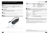
2-3. Bottom View
The bottom side of the JetCon 3701GP-U includes one 6-pin removable
terminal block connector.
The power range of JetCon 3701GP-U is from DC 44~57V with redundancy
and polarity reverse function.
To prevent interference and get better performance, it is strongly
suggest make a well earth grounding by the “Earth Ground Screw”.
Earth Ground
Scew
Terminal Block

11
2-4. Wiring the DC Power Inputs
Follow the steps below to wire JetCon 3701GP-U redundant DC power inputs.
[Note] The suitable electric wire ranges from 12 to 23 AWG.
1.
Insert the positive and negative wires into the V+ and V- contacts respectively
of the terminal block connector
2.
Tighten the wire-clamp screws to prevent the DC wires from being loosened.
3.
The Power 1 and Power 2 support power redundancy and polarity reverse
protection functions.
4.
It accepts positive or negative power system input, but Power 1 and Power 2
have to apply the same mode.

12
2-5. Connect the Dry Relay Output
JetCon 3701GP-U provides one dry relay output for fault power event.
The relay conductor ability is 24W when it connects with a DC 24V power source
and maximum current is 1A. In the following diagram shows how to make an alarm
circuit.
About the relay function, please refer section 4-4
2-6. LED Indicators
The front panel of JetCon 3701GP-U includes 2 Power LEDs, 1 LED for
Alarm Relay ,1 LED for Link Loss Forwarding status and 1 LED for port link
status. Following table gives descriptions of the function for each LED
indicator.

13
LED
Status
Description
Power 1
Green On
Power 1 is supplying DC power.
Off
No power is being supplied.
Power 2
Green On
Power 2 is supplying DC power.
Off
No power is being supplied.
PoE
Amber On
Output power is supplied
Amber Off
No output power
LLF
(Link Loss
Forwarding)
Red On
Link Loss
Off
Data Transfer
Alarm
Red on
PW1 or PW2 is disconnect.
Off
PW1 and PW2 Power Connect
SFP
Green on
Link
Fast Blinking
Link with speed 1000Mbps
Slow Blinking
Link with speed 100Mbps
RJ-45 port
Green On
Link
Bilking
Activity
Amber On
Link with Speed 1000Base T(X)
Amber Off
Link with Speed
10/100 Base T(X)
Table 1
2-7. Ports
The JetCon 3701GP-U supports IEEE 802.3 10Base-T, IEEE 802.3u 100Base-
T, IEEE 802.3ab 1000Base-T and IEEE 802.3z for Gigabit Fiber. This section
will introduce how to wiring, install the Ethernet Cable for RJ-45 connector and
SFP ports.
Gigabit TX ( RJ-45 connector)
All of RJ-45 ports will auto detect 10Base-T and 100Base-TX or 1000Base-T

14
(Gigabit RJ45 only) connections. Auto MDI/MDIX allows users to connect another
switch or workstation without changing straight through or crossover cabling. See
Figure A, B, C and D for the schematic diagram of straight through and crossover
cabling.
Fig A. Straight through Cabling
Schematic for 10/100Mbps
Fig. C Straight through cable
schematic for 1000Mbps
Fig B. Cross Over Cabling
Schematic for 10/100Mbps
Fig. D Cross over cable
schematic for 1000Mbps

The RJ-45 ports of JetCon 3701GP-U supports auto-MDI/MDI-X function without
any cable change when you use an Ethernet cable to connect other devices, such
as computers, switches or hubs.
Gigabit SFP port
The SFP port supports hot swappable function a and user can change SFP fiber
transceiver without system power off. This feature is useful for field site install if the
fiber signal cannot attach the other end device, just change the different SFP
transceiver type which with large power launch power budget. SFP port support
100/1000Mbps.
The Korenix provides various type of SFP transceiver for your application. Please
refer the order information.

3. Mounting Installation
3-1. DIN-Rail Mounting
The DIN-Rail clip is already attached on the rear side of JetCon 3701GP-U. JetCon
3701GP-U supports EN 50022 standard DIN Rail, in the following diagram includes
the dimension of EN 55022 DIN Rail for your reference.
The DIN rail should behind the
spring when install the JetCon
3701GP-U onto the standard DIN
Rail.
Follow the steps below to mount
the JetCon 3701GP-U to the
DIN-Rail track.
1. Insert the upper end of the
DIN-Rail clip into the back of
the DIN-Rail track from its
upper side
2. Lightly push the bottom of the
DIN-Rail clip into the track.
3. Check if the DIN-Rail clip is
tightly attached to the track.
4. To remove the JetCon
3701GP-U from the track,
reverse the steps above.

4. System Configuration
The JetCon 3701GP-U provides Ethernet signal transfer function from
electrical to optical and various packet handling and cable diagnostic features.
In this chapter, we will introduce how to configure those functions and benefits as
following topics.
4-1. Quality of Service (QoS)
4-2. Packet filtering
4-2. Link Loss Forwarding (LLF)
4-3. Event Alarm Relay Configuration
4-1. Quality of Service
The JetCon 3701GP-U supports 2 types of priority mechanisms - IEEE802.1Q
priority tag based CoS and ToS of IPv4. All the packets will be examined and
forwarding into high or low priority queues. The Quality of Service function is pre-
configured as enabled.
The weight round robin (WRR) ratio of high/low queue is 8:1. After 8 high priority
packets were progressed then 1 low priority packets.
IEEE 802.1Q tag-based CoS
The JetCon 3701GP-U will examine the 3 bits of priority field carried by a VLAN tag
and map it to the corresponding priority. A packet with priority field ranging from 0
to 3 will be treated as a low priority packet and will be stored in low priority queue. A
packet with priority field ranging from 4 to 7 will be treated as a high priority packet,
and will be stored in high priority query

IEEE 802.1Q Type of Service for IPv4 /IPv6 packet
JetCon 3701GP-U provides the IP layer ToS function by recognizing the priority
octet and mapping it to the corresponding priority. For an IPv4 packet, it is
embedded in the TOS (type of Service) Octet. For an IPv6 data packet, the
Traffic Class Octet is used to differentiate the Class of Service. When this
function is enabled, the JetCon 3701GP-U will automatically recognize the IP
version and capture the either the TOS field (IPv4) or Traffic Class field (IPv6).

4-2. Packet Filtering
To prevent broadcast packet flooding on the network, the JetCon 3701GP-U have
implemented broadcast packet control function. The port begins to drop incoming
broadcast packets if the received broadcast packet counts reach the threshold as
different link speed – 25Mbps at link speed 1000Mbps, 10Mbps at link speed
100Mbps and 1Mbps at link speed 10Mbps.
4-3. Link Loss Forwarding (L.L.F.)
The Link Loss Forwarding provides a real time hardware-based network activated
diagnostics mechanism. In usually, the Gigabit Media Converter on the end of
fiber cable should be equipped LLF function to provide better network
performance and reduce the maintenance cost.
The JetCon 3701GP-U provides 2-way Link Loss Forwarding function. About
the Link Loss Forwarding behaviors are described in following, please refer it.
Gigabit Fiber
Gigabit Copper
Gigabit Copper
Node A
Node B

In the above diagram includes node A, B and converter A,B. Both of converters
linked with Gigabit fiber. In traditional fiber network architecture; if the Gigabit
copper of node A link down, the node B will not have any information, just packet
can’t forward between A and B.
With the Link Loss Forwarding feature, the link down event of node A will forward
to converter A and B. Therefore, converter A will turn off the fiber signal and
converter B will turn off Gigabit copper signal to inform node B that port link down
event occurred until the node A port recovery. In some application, you also can
obtain an event alarm signal by enable the port event alarm function. Please refer
to the section 4-4.
The following procedures will introduce how to configure LLF function.
Step 1: power on the device A, B and connect the fiber and copper ports.
Step 2: Ensure the port link LEDs is working exactly.
Step 3: if the port link event occurred, the other port will be trigger and turn off by
the LLF mechanism.
Step 4: To start the transmission and retrieve the L.L.F. function, the LLF
Dipswitch should be reset again.
4-4. Event Alarm Relay Configuration
The connection of Event Alarm Relay already described in section 2-5 Connect
the Dry Relay output and this section will introduce how to enable it
/