Page is loading ...

1
WARNING: Because of the possible danger to person(s) or
property from accidents which may result from the improper
use of products, it is important that correct procedures be
followed. Products must be used in accordance with the
engineering information specified in the catalog. Proper
installation, maintenance and operation procedures must
be observed. The instructions in the instruction manuals
must be followed. Inspections should be made as necessary
to assure safe operation under prevailing conditions. Proper
guards and other suitable safety devices or procedures as
may be desirable or as may be specified in safety codes
should be provided, and are neither provided by ABB nor
are the responsibility of ABB. This unit and its associated
equipment must be installed, adjusted and maintained by
qualified personnel who are familiar with the construction
and operation of all equipment in the system and the
potential hazards involved. When risk to persons or property
may be involved, a holding device must be an integral part
of the driven equipment beyond the speed reducer output
shaft.
WARNING: To ensure the drive is not unexpectedly
started, turn off and lock-out or tag power source before
proceeding. Failure to observe these precautions could
result in bodily injury.
WARNING: All products over 25 kg (55 lbs) are noted on the
shipping package. Proper lifting practices are required for
these products.
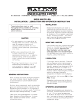
Instruction Manual for Dodge
®
Torque-Arm
™
Speed Reducers
Straight Bore & Taper Bushed
Sizes:
TXT105
TXT205
These instructions must be read thoroughly before installation or operation. This instruction manual was accurate at the time of
printing. Please see baldor.com for updated instruction manuals.
Note! The manufacturer of these products, Baldor Electric Company, became ABB Motors and Mechanical Inc. on
March 1, 2018. Nameplates, Declaration of Conformity and other collateral material may contain the company name of
Baldor Electric Company and the brand names of Baldor-Dodge and Baldor-Reliance until such time as all materials have
been updated to reflect our new corporate identity.
NOTE: This reducer is compatible with the ABB Ability
Smart Sensor, which can be installed in the adapter plug
labelled "smart sensor". The plug and sensor can be
moved to different locations as required by mounting
position.
Installation
1. Use eyebolt to lift reducer.
2. Determine the running position of the reducer. (See Fig. 1)
Note that the reducer is supplied with either 4 or 7 plugs;
4 around the sides for horizontal installations and 1 on
each face for vertical installations. These plugs must be
arranged relative to the running positions as follows:
Horizontal Installations: Install the magnetic drain plug
in the hole closest to the bottom of the reducer. Throwaway
the tape that covers the ller/ventilation plug in shipment
and install plug in topmost hole. Of the 3 remaining plugs
on the sides of the reducer, the lowest one is the minimum
oil level plug.
HORIZONAL APPLICATIONS
VERTICAL MOUNT
Position A
Position B
Position C
Position D
Position E
Position F
B = Breather
D = Drain
L = Level
P = Plug
Figure 1 - Mounting Positions
Vertical Installations: Install the ller/ventilation plug in
the hole provided in the top face of the reducer housing.
Use the hole in the bottom face for the magnetic drain plug.
Of the 5 remaining holes on the sides of the reducer, use
a plug in the upper housing half for the minimum oil level
plug.
3. The running position of the reducer in a horizontal
application is not limited to the four positions shown in
Figure 1. However, if running position is over 20’ either way
from position “B” or “D” in Fig. 1 sketches, or 5’ either way
from position “A” or “C,” the oil level plug cannot be safely
used to check the oil level, unless during the checking the
torque arm is disconnected and the reducer is swung to
within 20’/5° of the positions shown in Figure 1. Because
of the many possible positions of the reducer, it may be
necessary or desirable to make special adaptations using
the lubrication tting holes furnished along with other
standard pipe ttings, stand pipes and oil level gages as
required. 3.

2
4. Mount reducer on driven shaft as follows:
For Straight Bore: Mount reducer on driven shaft as close
to bearing as practical. If bushings are used, assemble
bushing in reducer rst. A set of bushings for one reducer
consists of one keyseated bushing and one plain bushing.
Extra length setscrews are furnished with the reducer. Driven
shaft should extend through full length of speed reducer.
Tighten both setscrews in each collar.
For Taper Bushed: Mount reducer on driven shaft per
instruction manual for tapered bushings.
5. Install sheave on input shaft as close to reducer as
practical. (See Fig. 2.)
Figure 2 - Installation of Sheave
6. Install motor and V-belt drive so belt pull will approximately
be at right angles to the center line between driven and input
shaft. (See Fig. 3.) This will permit tightening the V-belt drive
with the torque arm.
Figure 3 - Installation of Motor
7. Install torque arm and adapter plates using the long
reducer bolts. The bolts may be shifted to any of the holes
on the input end of the reducer.
8. Install torque arm fulcrum on a rigid support so that the
torque arm will be approximately at right angles (±30º) to
the center line through the driven shaft and the torque arm
anchor screw. (See Fig. 4.) Make sure that there is sufcient
take-up in the turnbuckle for belt tension adjustment when
using V-belt drive.
Figure 4 - Installation of Torque Arm Fulcrum
CAUTION: Unit is shipped without oil. Add proper amount
of recommended lubricant before operating. Failure to
observe these precautions could result in damage to, or
destruction of, the equipment.
9. Fill gear reducer with recommended lubricant.
LUBRICATION
Use a high grade petroleum base, rust and oxidation inhibited
(R & 0) gear oil-see tables. Follow instructions on reducer
nameplate, warning tags, and in the installation manual.
Under average industrial operating conditions, the lubricant
should be changed every 2500 hours of operation or every 6
months, whichever occurs rst. Drain reducer and ush with
kerosene, clean magnetic drain plug and rell to proper level
with new lubricant. Check oil level regularly.
CAUTION: Extreme pressure (EP) lubricants are not
recommended for average operating conditions. Failure to
observe these precautions could result In damage to, or
destruction of, the equipment.
CAUTION: Too much oil will cause overheating and too
little will result in gear failure. Check oil level frequently.
Failure to observe these precautions could result in
damage to, or destruction of, the equipment.
Under extreme operating conditions, such as rapid rise and fall
of temperature, dust, dirt, chemical particles, chemical fumes, or
oil sump temperatures above 200”F, the oil should be changed
every 1 to 3 months depending on severity of conditions.
CAUTION: Do not use oils containing slippery additives
such as graphite or molybdenum disulphide in the reducer
when backstop is used. These additives will destroy sprag
action. Failure to observe these pre-cautions could result
in damage to, or destruction of, the equipment.

3
Table 1 - Oil Volume ③
Reducer
Size
Volume of Oil Required to Fill Reducer to Oil Level Plug
➀ Position A ➀ Position B ➀ Position C ➀ Position D ➀ Position E ➀ Position F
Fluid
Ounces
(Approx)
Quarts
➁
(Approx)
Liters
(Approx)
Fluid
Ounces
(Approx)
Quarts
➁
(Approx)
Liters
(Approx)
Fluid
Ounces
(Approx)
Quarts
➁
(Approx)
Liters
(Approx)
Fluid
Ounces
(Approx)
Quarts
➁
(Approx)
Liters
(Approx)
Fluid
Ounces
(Approx)
Quarts
➁
(Approx)
Liters
(Approx)
Fluid
Ounces
(Approx)
Quarts
➁
(Approx)
Liters
(Approx)
TXT105 20 5/8 .59 24 3/4 .71 20 5/8 .59 24 3/4 .71 36 1-1/8 1.06 44 1-3/8 1.30
TXT205 24 3/4 .71 28 7/8 .83 28 7/8 .83 28 7/8 .83 56 1-3/4 1.66 72 2-1/4 2.13
➀ Refer to Figure 1 on page 2 for mounting positions
➁ U.S. Measure: 1 quart = 32 fluid ounces = .04646 liters
③ Below 15 RPM output speed, oil level must be adjusted
NOTE: If reducer position is to vary from those shown in Figure 1 either more or less oil may be required. Consult Dodge Product Support.
Table 2 -Lubrication Recommendations -ISO Grades ①
Output
RPM
For Ambient Temperatures of 50° thru 125°
Reducer Size
1 2 3 4 5 6 7 8 9 10 12 13 14 15
301-400 320 320 220 220 220 220 220 220 220 220 220 220 220 220
201-300 320 320 220 220 220 220 220 220 220 220 220 220 220 220
151-200 320 320 220 220 220 220 220 220 220 220 220 220 220 220
126-150 320 320 320 220 220 220 220 220 220 220 220 220 220 220
101-125 320 320 320 320 220 220 220 220 220 220 220 220 220 220
81-100 320 320 320 320 320 220 220 220 220 220 220 220 220 220
41-80 320 320 320 320 320 220 220 220 220 220 220 220 220 220
11-40 320 320 320 320 320 320 320 320 320 320 220 220 220 220
1-10 320 320 320 320 320 320 320 320 320 320 320 320 320 320
Output
RPM
For Ambient Temperatures of 15° thru 60°
Reducer Size
1 2 3 4 5 6 7 8 9 10 12 13 14 15
301-400 220 220 150 150 150 150 150 150 150 150 150 150 150 150
201-300 220 220 150 150 150 150 150 150 150 150 150 150 150 150
151-200 220 220 150 150 150 150 150 150 150 150 150 150 150 150
126-150 220 220 220 150 150 150 150 150 150 150 150 150 150 150
101-125 220 220 220 220 150 150 150 150 150 150 150 150 150 150
81-100 220 220 220 220 220 150 150 150 150 150 150 150 150 150
41-80 220 220 220 220 220 150 150 150 150 150 150 150 150 150
11-40 220 220 220 220 220 220 220 220 220 220 150 150 150 150
1-10 220 220 220 220 220 220 220 220 220 220 220 220 220 220
For reducers operating in ambient temperatures between -22°F (-30°C) and 20°F (-6.6°C), use a synthetic hydrocarbon lubricant. 100 ISO grade or AGMA 35 grade (lor
example - Mobil SHC627).
Above 125°F (51 .6°C), consult DODGE Gear Application Engineering (864) 288-9050 for lubrication recommendation.
NOTE: Pour point of lubricant selected should be at least 10'F lower than expected minimum ambient starting temperature. Refer to Viscosity Equivalency chart for lubricants
viscosity classification equivalents.
Special lubricants may be required for food and drug industry applications where contact with the product being manufactured may occur. Consult a lubrication manufacturers
representative for his recommendation.

4
MOTOR MOUNT INSTALLATION
Note: Refer to photo for position of all parts before
installation.
1. Remove the two or three bolts required for mounting the
TAM Motor Mount from the reducer housing. Install the
front and rear supports (2) using the new reducer bolts (1)
supplied with the motor mount. Make sure support anges
face output side of reducer. Tighten bolts securely.
2. Mount bottom plate (3) on supports with bolts supplied.
Insert bolts (7) from top through slotted holes. Add at
washer, lockwasher, and nut. Hand tighten.
3. Thread two nuts (6) on each threaded stud (5) leaving
approximately 1" of stud protruding at one end. Insert
threaded stud with 1" of threads through corner holes of
bottom plate, thread a hex nut (6) on the stud and tighten
securely.
4. Slide top plate (4) over the threaded stud, making sure
center handling hole is positioned opposite input side of
reducer. Thread a hex nut (6) on the studs and tighten
securely.
WARNING: If electrical connections to motor are installed
at this time, disconnect and lock out power supply before
proceeding. Failure to observe this precaution may result
in bodily injury.
5. Locate the proper position for the motor and bolt to the top
plate. Tighten bolts securely.
6. Install motor sheave and reducer sheave as close to
motor and reducer housings as possible. Accurately align
the motor and reducer sheave by sliding bottom plate in
relation to supports. Tighten bolts (7) securely.
7. Install V-belts and tension belts by alternately adjusting
nuts (6) on the threaded studs (jackscrews). Make certain
that all bolts are securely tightened, the V-belt drive is
properly aligned and the belt guard is installed before
operating the drive.
① Rear Supports
⑦ Bolts
⑥ Hex Nuts
① Reducer Bolts
⑤ Threaded Stud
③ Bottom Plate
④ Top Plate
GUIDELINES FOR TORQUE-ARM REDUCER
LONG-TERM STORAGE
During periods of long storage, or when waiting for delivery or
installation of other equipment, special care should be taken to
protect a gear reducer to have it ready to be in the best condition
when placed into service.
By taking special precautions, problems such as seal leakage
and reducer failure due to the lack of lubrication, improper
lubrication quantity, or contamination can be avoided. The
following precautions will protect gear reducers during periods
of extended storage:
Preparation
1. Drain the oil from the unit. Add a vapor phase corrosion
inhibiting oil (VCI-105 oil by Daubert Chemical Co.) in
accordance with Table 3.
2. Seal the unit air tight. Replace the vent plug with a standard
pipe plug and wire the vent to the unit.
3. Cover the shaft extension with a waxy rust preventative
compound that will keep oxygen away from the bare metal.
(Non-Rust X-110 by Daubert Chemical Co.)
4. The instruction manuals and lubrication tags are paper and
must be kept dry. Either remove these documents and store
them inside or cover the unit with a durable waterproof cover
which can keep moisture away.
5. Protect the reducer from dust, moisture, and other
contaminants by storing the unit in a dry area.
6. In damp environments, the reducer should be packed inside
a moisture-proof container or an envelope of polyethylene
containing a desiccant material. If the reducer is to be stored
outdoors, cover the entire exterior with a rust preventative.
When Placing the Reducer into Service
1. Assemble the vent plug into the proper hole.
2. Clean the shaft extensions with a suitable solvent.
3. Fill the unit to the proper oil level using a recommended
lubricant. The VCI oil will not affect the new lubricant.
4. Follow the installation instructions provided in this manual.
Table 3 - Quantities of VCI #105 Oil
Case Size Quarts or Liters
TXT105,TXT205 .1
VCI #105 & #10 are interchangeable.
VCI #105 is more readily available.

5
40
18
80
80
82
99
12
102,
104,
106
100
84
88
90
92, 94
38
36
68
69
70
72
74
60
58
58 14
56
62
64
28
42
26
30
96
100
55
76
16, 20,
22, 24, 25
98
102, 104, 106
40
38
36
60
58
15
66
54
67
14
56
62
64
28
42
26
30
96
100
16, 20,
22, 24, 25
98
102, 104, 106
Straight Bore Taper Bushed
Torque-Arm Assembly
Backstop
Assembly
Adapter Plate Assembly

6
Part Number Tables TXT 105 and TXT205
Reference Name of Part
No.
Req'd
TXT105
Part No.
TXT205
Part No.
12 Backstop Assembly 1 242101 252101
15
①
16
18
①
HOUSING
Air Vent
Housing Bolt
Adapter - Housing Bolt
Smart Sensor Adapter
1
1
②
2
1
241186
241237
411418
411420
966905
242194
241237
411418
411420
966905
20
22
24
①
①
①
25
26
30
36
Lockwasher
Hex Nut
Dowel Pin
Pipe Plug
Smart Sensor Adapter
Magnetic Plug
Washer
Backstop Cover
Backstop Cover Screw
Input Shaft Pinion
③
③
2
2
1
1
4
1
4
1
419011
407087
420091
430031
966905
430060
419092
242221
415022
251020
419011
407087
420091
430031
966905
430060
419204
243221
415022
242214
54
55
56
58
60
OUTPUT HUB ASSEMBLY ④
Straight Bore
Taper Bushed
⑤ Output Hub (Straight Bore)
⑤ Output Hub (Taper Bushed)
⑤ Output Gear
⑤ Output Gear Key
⑤ Output Hub Snap Ring
1
1
1
1
1
1
2
390151
390878
241208
241265
241007
241217
421013
392110
392111
242208
242134
242181
433399
421017
66
67
68
69
Output Hub Collar ⑥
Collar Screw ⑥
Bushing Back-up Plate ⑦
Retaining Ring ⑦
2
4
2
2
241209
400062
241266
421111
242209
400094
242137
421112
70
BUSHING
ASSEMBLY
④ ⑦
1" Bore 1 241278 . . . . . .
1-1/16" Bore 1 241280 . . . . . .
1-1/8" Bore 1 241282 242146
1-3/16" Bore 1 241286 242148
1-1/4 " Bore 1 241288 242150
1-5/16" Bore 1 241290 242152
1/3/8" Bore 1 . . . . . . 242154
1-7/16" Bore 1 241292 242156
1-1/2" Bore 1 . . . . . . 242158
1-5/8" Bore 1 . . . . . . 242162
1-11/16" Bore 1 . . . . . . 242164
1-3/4" Bore 1 . . . . . . 242166
1-7/8" Bore 1 . . . . . . . . . . . .
1-15/16" Bore 1 . . . . . . 242168
28
38
64
SEAL KIT ④ ⑧
⑤ Backstop Cover Gasket
⑤ Input Seal
⑤ Output Seal
1
1
1
2
272700
242220
242211
242210
272701
243220
244211
242210
① Not shown on drawing.
② 4 required on TXT105; 5 required on TXT205.
③ 6 required on TXT105; 7 required on TXT205.
④ Includes parts listed immediately below. Bushing assembly includes 2 bushings.
⑤ Parts make up the assemblies under which they are listed.
Part Number Tables TXT 105 and TXT205
Reference Name of Part
No.
Req'd
TXT105
Part No.
TXT205
Part No.
BEARING KIT ④ ⑧ 1 389910 389911
40 ⑤ Input Shaft Brg. (Input) 1 424076 424078
42 ⑤ Input Shaft Brg. (Backstop) 1 424012 424000
62 ⑤ Output Hub Bearing 2 424020 424022
① Input Shaft Key 1 443013 443052
① Max Bore Key ⑥ 1 241296 242296
72 ⑤ Bushing Screw 6 411390 411390
74 ⑤ Lockwasher 6 419010 419010
76
⑤ Key,
Bushing to
Shaft
1" Bore
1-1/16" Bore
1-1/8" Bore
1-3/16" Bore
1-1/4 " Bore
1-5/16" Bore
1/3/8" Bore
1-7/16" Bore
1-1/2" Bore
1-5/8" Bore
1-11/16" Bore
1-3/4" Bore
1-7/8" Bore
1-15/16" Bore
1
1
1
1
1
1
1
1
1
1
1
1
1
1
443274
443274
443271
241308
241307
241306
. . . . . .
241305
. . . . . .
. . . . . .
. . . . . .
. . . . . .
. . . . . .
. . . . . .
. . . . . .
. . . . . .
443281
443281
443281
443280
443280
443282
443282
242172
242171
242170
. . . . . .
443283
①
①
⑤ Key, Bushing to Output Hub
⑤ Key, Bushing to Output Hub
1 ⑨
1 ⑩
443272
443273
443284
. . . . . .
80
82
84
86
TORQUE-ARM ASSEMBLY ④
⑤ Rod End
⑤ Hex Nut
⑤ Turnbuckle
⑤ Extension
1
1
1
1
1
241097
241245
407093
241246
2431247
243097
243245
407095
243246
243247
88
90
92
94
⑤ L.H. Hex Nut
⑤ Fulcrum
⑤ Fulcrum Screw
⑤ Hex Nut
1
1
1
1
407242
241249
411456
407091
407091
242249
411484
407093
96
98
99
100
102
104
106
ADAPTER ASSEMBLY ④
⑤ R.H. Adapter Plate
⑤ L.H. Adapter Plate
⑤ Adapter Plate Assembly
⑤ Adapter Bushing
⑤ Adapter Bolt
⑤ Lockwasher
⑤ Hex Nut
1
1
1
1
1
1
1
1
259151
241242
241241
. . . . . .
242243
411412
419011
407087
259152
242136
242135
. . . . . .
243243
411437
419012
407089
⑥ Straight bore only
⑦ Taper bushed only
⑧ Recommended spare parts
⑨ On size TXT105 for 1" bores; TXT205 for 1-1/8" bores thru 1-1/2" bores.
⑩ One size - TXT105 for 1-1/16" bores and 1 -1/8" bores.
Table 4 - Manufacturers' Part Numbers
For Replacement Output Hub Bearings
TORQUE-ARM
Reducer Drive Size
Output Bearing
Part Number
TXT105 424020
TXT205 424022
Table 5 - Manufacturers' Part Numbers
For Replacement Input Shaft Bearings
TORQUE-ARM
Reducer Drive Size
Input Bearing
Input Side
Input Bearing
Backstop Side
Part Number Part Number
TXT105 424076 424012
TXT205 424078 424000

7
REPLACEMENT OF PARTS
A DODGE TORQUE-ARM Speed Reducer can be disassembled
and reassembled by careful attention to the instructions
following, using tools normally found in a maintenance
department.
Cleanliness is very important to prevent the introduction of dirt
into the bearings and other parts of the reducer. A tank of clean
solvent, an arbor press, and equipment for heating bearings
and gears should be available for shrinking these parts on
shafts.
Our factory is prepared to repair reducers for customers who
do not have proper facilities or who for any reason desire
factory service.
The oil seals are of the rubbing type and considerable care
should be used during disassembly and reassembly to avoid
damage to the surface on which the seals rub.
The keyseat in the input shaft as well as any sharp edges on
the output hub should be covered with tape or paper before
disassembly or reassembly. Also be careful to remove any burrs
or nicks on surfaces of the input shaft or output hub before
disassembly or reassembly.
ORDERING PARTS
When ordering parts for reducer, specify reducer size number,
reducer serial number, part name, part number and quantity.
It is strongly recommended that when a pinion or gear is
replaced, the mating gear or pinion be replaced also.
If the large gear on the output hub must be replaced, it is
recommended that an output hub assembly with a gear
assembled on the hub be ordered to secure undamaged
surfaces on the output hub where the oil seals rub. However, if it
is desired to use the old output hub, press the gear and bearing
off and examine the rubbing surface under the oil seal carefully
for possible scratching or other damage resulting from the
pressing operation. To prevent oil leakage at the shaft oil seals
the smooth surface of the output hub must not be damaged.
If any parts must be pressed from a shaft or from the output
hub, this should be done before ordering parts to make sure
that none of the bearings or other parts are damaged in
removal. Do not press against outer race of any bearing.
Because old shaft oil seals may be damaged in disassembly it
is advisable to order replacements for these parts.
REMOVING REDUCER FROM SHAFT
WARNING: External loads may cause machine movement.
Block machine before removing any drive train
components. Failure to observe these precautions could
result in bodily injury.
STRAIGHT BORE
Loosen screws in both output hub collars. Remove the collar
next to end of shaft. This exposes three puller holes in output
hub to permit use of wheel puller. In removing reducer from
shaft be careful not to damage ends of hub.
TAPER BUSHED
1. Remove bushing screws.
2. Place the screws in the threaded holes provided in the
bushing anges. Tighten the screws alternately and
evenly until the bushings are free on the shaft. For ease of
tightening screws make sure screw threads and threaded
holes in bushing anges are clean.
3. Remove the outside bushing, the reducer and then the
inboard bushing.
DISASSEMBLY
1. Position reducer on its side and remove all bolts. Gently tap
the output hub and input shaft with a soft hammer (rawhide
not a lead hammer) to separate the housing halves. Open
housing evenly to prevent damage to the parts inside.
2. Lift shaft, gear and bearing assemblies from housing.
3. Remove seals from housing.
REASSEMBLY
1. Output Hub Assembly: Heat gear to 325"F to 350"F to
shrink onto hub. Heat bearings to 250"F to 270"F to shrink
onto hub. Any injury to the hub surfaces where the oil seals
rub will cause leakage making it necessary to use a new
hub.
2. Input Shaft Assembly: Shaft and pinion are integral. Press
bearings on shaft. Press against inner (not outer) race of
bearings.
3. Drive the two dowel pins into place in the right-hand
housing half. Position right half of housing (as shown in
drawing) on blocks to allow clearance for protruding end of
output hub.
4. Place output hub assembly in housing half. Place input
shaft assembly in housing half. Tap lightly with a soft
hammer (rawhide not lead hammer) until bearings are
properly seated in the housing. Make sure that the snap
rings on the O.D. of the bearings come into contact with the
housing.
5. Clean housing ange surfaces on both halves, making
sure not to nick or scratch ange face. Place a new bead
of gasket replacer on ange face and spread evenly over
entire ange leaving no bare spots. Note: If reducer was
originally supplied with a housing gasket, do not use gasket
replacer. Reorder gasket per part number given in parts list.
Place other housing half into position and tap with a soft
hammer until housing bolts can be used to draw housing
halves together. Torque housing bolts per torque values
listed below:
Housing Bolt Torque Values
Reducer Size
Recommended Torque
(in.-lbs.)
TXT105, TXT205 360
6. Extreme care should be used in installing seals on input
shaft and output hub to avoid damage to seals due to
contact with sharp edges of the keyseat in the input shaft
or the retaining ring groove in the output hub. This danger
of damage and consequent oil leakage can be decreased
by covering the keyseat and groove with tape or paper
which can be removed subsequently. Chamfer or deburr
housing bore if end of bore is sharp or rough. Fill cavity
between lips of seal with grease. Seals should be pressed
or tapped with a soft hammer evenly into place in the
housing; apply force only on outer corner seals. A slight oil
leakage at the seals may be evident during initial running in,
but will disappear unless the seals have been damaged.

—
ABB Motors and Mechanical Inc.
5711 R. S. Boreham Jr. Street
Fort Smith, AR 72901
Ph: 1.479.646.4711
Mechanical Power Transmission Support
Ph: 1.864.297.4800
new.abb.com/mechanical-power-transmission
baldor.com
*1674-1119*
© ABB Motors and Mechanical Inc.
MN1674 (Replaces 499919)
All Rights Reserved. Printed in USA.
11/2019
OIL VISCOSITY EQUIVALENCY CHART
2000
1000
800
600
500
400
300
200
100
80
60
50
40
30
20
10
8
6
5
4
3
2
70
60
50
40
30
20
10
8
5
4
9
7
6
1500
1000
680
460
320
220
150
100
68
8A
8
7
6
5
4
3
2
85W
250
140
90
80W
46
32
22
15
10
7
5
1
75W
3
2
300
200
150
100
80
70
60
50
40
35
32
400
500
600
800
1000
1500
2000
3000
4000
5000
6000
8000
10,000
cSt/
40°C 100°C
cSt/ ISO
VG
AGMA
GRADES
GRADES
GEAR OILS
SUS/
100°F
SUS/
210°F
SAE
KINEMATIC
VISCOSITIES
SAYBOLT
VISCOSITIES
200
300
100
90
80
70
60
55
50
45
40
VISCOSITIES CAN BE
RELATED HORIZONTALLY
ONLY.
VISCOSITIES BASED ON
96 VI SINGLE GRADE
OILS.
ISO ARE SPECIFIED AT
40°C.
AGMA ARE SPECIFIED AT
40°C.
SAE 75W, 80W, AND 85W
SPECIFIED AT LOW
TEMPERATURE. EQUIVALENT
VISCOSITIES FOR 100°F
AND 200°F ARE SHOWN.
SAE 90 TO 250 SPECIFIED
AT 100°C.
/