Page is loading ...

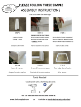
For wood installation:
Determine the desired location(s) and
finished height of the post sleeve from the
deck surface. Trim the post sleeve to the
required length.
Trim the non-routed end of the 4-in. x 4-in.
wood post insert if required. The wood
post insert is typically 1-in. to 2-in. shorter
than the post sleeve length.
Drill four 3/8-in. holes at the marked
locations, drilling through the deck
board and the reinforcement boards.
If necessary, drill a 3/8-in. drainage
hole in square through deck board and
reinforcement boards for drainage.
Align the mount holes over the drilled
holes.
Slide the post sleeve (not included with
mount) over the 4-in. x 4-in. wood post
insert until it contacts the base of the
mount.
Note: If using post skirts, make sure to
slide post skirt over the post sleeve before
installing the bottom rail.
Insert 5/16-in. x 5-in. galvanized hex bolts
through the bracket holes into the drilled
holes and attach a washer and nut to
each bolt (galvanized bolts and nuts, not
included) under the deck.
Only hand tighten nuts at this time.
6
Use the base of the mount as a template
and mark the four corner holes on the
deck surface. If necessary, mark inside
the square of the bracket on the deck
surface to create a drainage hole.
4
Insert the routed end of the 4-in. x 4-in.
wood post insert into the mount, and
check for level and plumb.
If necessary, place a shim under the
mount to make the post plumb and true.
If the wood post insert is loose within the
mounting bracket, secure the wood post
insert with three #8 x 1-in. flat-head screws
(not included) on three sides of the mount
through the pre-punched holes. Tighten
and secure the four bolts underneath the
reinforcement boards with the 5/16-in.
fender washer (included In kit) and 5/16-in.
galvanized hex nuts (not included). Do not
overtighten.
5
1
2
3
The most recent installation instructions can be found on our website. Please visit berondecking.com or call Consumer and Technical Support at 800-573-8841.
Distributed By
Post Sleeve Surface Mount with Wood Insert Installation Instructions

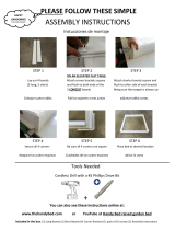
1
Insert the routed end of the 4-in. x 4-in.
wood post insert into the mount, and
check for level and plumb. If necessary,
place a shim under the mount to make
the post plumb and true. If the wood
post insert is loose within the mounting
bracket, secure the wood post insert
with three #8 x 1-in. flat-head screws (not
included) on three sides of the mount
through the pre-punched holes.
5
Determine the desired location(s) and
finished height of the post sleeve from the
deck surface. Trim the post sleeve to the
required length.
Trim the non-routed end of the 4-in. x 4-in.
wood post insert if required. The wood
post insert is typically 1-in. to 2-in. shorter
than the post sleeve length.
Slide the post sleeve (not included with
mount) over the 4 in. x 4 in. wood post
insert until it contacts the base of the
mount.
Note: If using post skirts, make sure to
slide post skirt over the post sleeve before
installing the bottom rail.
6
Using a 1/4-in. masonry drill bit, drill the
holes into the concrete base to a depth of
at least 1/2-in. deeper than the length of
the 1/4-in. x 3-in. Wedge-Bolt Anchors.
Ensure the holes are clean of dust and
debris prior to inserting bolts.
Align the mount holes over the drilled
holes.
Use the base of the mount as a template
and mark the four corner holes for the
concrete fastener Wedge-Bolt Anchors
(included in kit).
Fasten mount to concrete as required
by applicable building codes. Insert the
four concrete Wedge-Bolt Anchors into
the corner holes of the mount. Begin
tightening the anchor bolts by rotating
clockwise and applying pressure
downward towards the mount base. This
will engage the first few threads as the
anchor bolt begins to advance. Continue
tightening until the head of the anchor
bolt is firmly seated against the post
mount base.
Repeat for the remaining fasteners
ensuring the base stays plumb and true.
3
2
4
The most recent installation instructions can be found on our website. Please visit berondecking.com or call Consumer and Technical Support at 800-573-8841.
For concrete installation:
Post Sleeve Surface Mount with Wood Insert Installation Instructions

Design Grid
Cuadrícula de diseño
Grille de conception
FIB-0365-LIT 4/16 Rev A
berondecking.com
1-800-573-8841
/