Page is loading ...

Swing•N•Slide • 1212 Barberry Drive • Janesville, Wisconsin 53545
Visit our web site at: www.swing-n-slide.com/timberbilt or call us at 1-800-888-1232
TURBO TUBE
SLIDE
®
with Turbo Tower Kit
ASSEMBLY INSTRUCTIONS FOR ADDING THIS KIT
TO THE TIMBER•BILT
™
PINNACLE
™
INSTRUCCIONES DE ENSAMBLE PARA ADHERIR ESTE EQUIPO AL
TIMBER•BILT
™
PINNACLE
™
INSTRUCTIONS D’ASSEMBLAGE POUR AJOUTER CET ENSEMBLE À
L'UNITÉ PINNACLE
MC
DE TIMBER•BILT
MC
TB 1404

2
IMPORTANT! This product is intended for single family residential use only
and not intended for use in any public setting. Placement in
any public setting constitutes a misuse of this product.
REQUIRED SAFETY INSTALLATION INSTRUCTIONS
ANCHORING INFORMATION According to ASTM requirements, all rope ends must be anchored to the ground. If soil
conditions permit stakes to be pulled out easily, cementing into ground is necessary. In addition, Swing•N•Slide recommends
that all units be anchored to the ground. For quick and easy staking, purchase Swing•N•Slide NE 4521 Anchor-It Ground
Anchors.
• When anchoring the unit to the ground using wooden stakes, use 2" x 4" x 18" (45mm x 95mm x 457mm) pressure-
treated stakes. Pound stakes into ground at least 12" (305mm) at all inside corners of the posts (including A-frame legs and
climbing unit posts). Attach with four (4) 16D galvanized nails per stake into each 4" x 4" (95mm x 95mm) post.
• When anchoring a climbing rope with wooden stakes, anchor the rope end. Use a 2" x 4" x 18" (45mm x 95mm x
457mm) pressure-treated stake. Drill a 1-1/4" (32mm) or 1-1/8" (29mm) hole through the stake approximately 1-1/2" (38mm)
from the top of the stake. Cement stake into ground, leaving only the hole exposed. Insert rope end through hole in stake and
tie a knot in the rope to secure.
• Once the unit is completely assembled and before children are allowed to play on it, proper shock-absorbing
surfacing material must be installed. This may be accomplished by using loose-fill materials at a suf ficient depth. The
Consumer Product Safety Commission “Handbook for Public Playground Safety” lists the following materials and required
depths that are sufficient for home/residential application. For fall height protection up to 9 ft. (2.742m) [recommended for
Swing•N•Slide kits]:
CRITICAL HEIGHTS OF TESTED MATERIALS
MATERIAL UNCOMPRESSED DEPTH COMPRESSED DEPTH
6 inch 9 inch 12 inch 9 inch
Wood Chips* 7 feet 10 feet 11 feet 10 feet
Double Shredded Bark Mulch 6 feet 10 feet 11 feet 7 feet
Engineered Wood Fibers** 6 feet 7 feet >12 feet 6 feet
Fine Sand 5 feet 5 feet 9 feet 5 feet
Coarse Sand 5 feet 5 feet 6 feet 4 feet
Fine Gravel 6 feet 7 feet 10 feet 6 feet
Medium Gravel 5 feet 5 feet 6 feet 5 feet
Shredded Tires*** 10-12 feet N/A N/A N/A
* This product was referred to as Wood Mulch in previous versions of the Handbook for Playground Safety . The term Wood Chips more accurately describes
the product.
** This product was referred to as Uniform W ood Chips in previous versions of the Handbook for Playground Safety . In the playground industry, the product is
more commonly known as Engineered Wood Fibers.
*** This data is from tests conducted by independent testing laboratories on a 6 inch depth of uncompressed shredded tire samples produced by four
manufacturers. The tests reported critical heights which varied from 10 feet to greater than 12 feet. It is recommended that persons seeking t o install
shredded tires as a protective surface request test data from the supplier showing the critical height of the material when it was tested in accordance
with ASTM F 1292.
When properly installed, shock absorbing material will completely cover the horizontal baseboards on climbing units. This
protective surfacing must extend a minimum of 6 ft. (1.828m) in all directions from the perimeter of the equipment or from the
outermost edges of any component. For example, a slide extending beyond the platform must have protective surfacing at least
6 ft. (1.828mm) out from both sides as well as the end. For swings, with a 7' pivot point, the protective surface must extend at
least 14 ft. out from both the back and front of the swing when the swing is in its rest position.

INSTALLATION:
1. Read instructions completely prior to beginning assembly.
2. Do not deviate from these plans or alter design.
3. Be sure all hardware is tightened securely and flush to the intended member . Any caps provided which go over exposed
bolts must be fastened securely.
4. Upon final assembly, bolt ends shall not protrude beyond the nuts more than the diameter of the bolt when the nuts are
tightened to a torque between 20 & 25 lbf.in. (2.3 & 2.8 N.m). Remove any sharp edges with a metal file.
5. Place the equipment on level ground, not less than six feet (1.8 meters) from any structure or obstruction such as a
fence, garage, house, overhanging branches, laundry lines or electrical wires.
6. Do not install home playground equipment over concrete, asphalt, packed earth or any other hard surface. A fall onto a
hard surface can result in serious injury to the equipment user .
7. Verify that suspended ropes and chains (except those used for swings) are secured at both ends so that they cannot be
looped back on themselves.
8. To prevent serious injury, children must not be allowed in the area during assembly and they must not be allowed to use
the equipment until it is properly installed.
9. Save this plan for future reference.
The Sun: Slides should not have a southern exposure unless they are shaded from mid-day and afternoon sun. Unshaded
slides facing south can get hot and cause discomfort to bare skin. Northern exposures or shaded areas are definitely best.
OPERATION:
1. On-site adult supervision must be provided for children of all ages.
2. Be sure to teach children the following before allowing them to use the equipment:
A. Do not walk close to, in front of, behind or between moving items.
B. Do not twist swing or any other accessory chains or ropes or loop them over the beam as this will reduce the
strength of the chain or rope.
C. Do not swing empty seats or other accessories.
D. Sit in the center of the swing seat and other accessories with full weight on seat.
E. Do not use equipment in a manner other than intended.
F. Do not get off equipment while it is in motion.
G. Do not climb on the equipment when it is wet.
H. Do not attach items to the playground equipment that are not specifically designed for use with Swing-N-Slide
equipment, such as, but not limited to, jump ropes, clothesline, pet leashes, cables and chain as they may cause a
strangulation hazard.
3. Only one child per planned occupant seat should be allowed on this set at one time. Individual accessory weight
limitations may vary, see packaging for details.
4. Dress children appropriately for play. Avoid clothing with draw strings and loose fitting clothes which could become
entangled or snagged on equipment.
Safety First
PARENTS: Before building a backyard play area please take the time to read all
instructions completely and caution your children accordingly. Observing the following
statements and warnings reduces the likelihood of serious or fatal injuries.
When building this kit, at least two people are required for lifting and holding beams, frames or other heavy
assemblies in position before bolting or nailing. Special precautions must be taken when handling treated wood.
Contact your local supplier for specific information.
SAFETY - Wear safety glasses to protect your eyes from flying wood chips when cutting or drilling. Use a dust mask.
Blunt nail points to prevent wood from splitting. To prevent splinters, sand the corners, edges, and all the points of the
wood by wrapping a piece of 80 grit sandpaper around a block of wood and sanding.
3
CAUTION
SAFETY INSTRUCTIONS

4
Please read all of the Safety and Maintenance information on pages 2-4. Read through the remainder of this plan and familiarize
yourself with the lumber component guide, parts & hardware guide, installation directions and illustrations of this unit. Iden tify all
the components and check them off on the lumber, parts and hardware guides.
This plan is written and illustrated to provide you with the easiest method of assembly . If you experience problems during
assembly or are missing any components, please contact us at 1-800-888-1232, Monday through Friday , 8:00 a.m. - 5:00 p.m.
Central Time.
It is recommended that a shock absorbing material
should extend a minimum of 6 feet in all directions from
the perimeter of stationary equipment such as climbers
and slides. However, because children may deliberately
jump from a moving swing, the shock absorbing
material should extend in the front and rear of a swing
a minimum distance of 2 times the height of the pivot
point measured from a point directly beneath the pivot
on the supporting structure.
Example: For swings with a 7' pivot point, protective
surface must extend at least 14' out from
both the back and front of the swing when
the swing is in its rest position.
WARNING: Lawn swings are designed for use by children two years of age and older . Use by children under the age of two
can result in entrapment between the seats and back areas. NEVER place children in a rearward facing position or with legs
between seat and backrest because the child's body may pass through the opening causing entrapment of the child's head.
Maintenance:
1. Check all nuts and bolts twice monthly during the usage season for tightness and tighten as required. It is particularly
important that this procedure be followed at the beginning of each season.
2. Remove plastic swing seats and other plastic accessories and take indoors, or do not use when the temperature drops
below 0° F.
3. Oil all metallic moving parts monthly during usage period.
4. Check all hardware and equipment for sharp edges twice monthly during usage season and replace them as necessary . It is
especially important to do this at the beginning of each new season.
5. Check swing seats and protective sleeves for cracks. Cracks in the seat or sleeves are signs of deterioration. If these
conditions exist replace swing seat immediately. Call 1-800-888-1232 for more information about replacement.
6. Check chains, ropes and cables monthly during the usage season for signs of deterioration, severe rusting or excessive
wear (especially near the top swing hanger or at the seat connection). If these conditions exist replace af fected accessory
immediately. Call 1-800-888-1232 for more information about replacement.
7. Use a water seal on your gym set to protect the wood and prevent cracking and warping.
8. Sand rusted areas on tubular members and repaint using a nonlead-based paint meeting the requirements of
Title 16 CFR part 1303.
Disposal:
1. When the activity center is to be taken out of service, remove all play components and disassemble Dispose in such a way
that no unreasonable hazards will exist at the time the activity center will be disposed of. Dispose of following local dispos al
requirements.
SAFETY INSTRUCTIONS
(continued)
MINIMUM USE ZONE
BEFORE YOU BEGIN
14'
6'
6'
6'
6'
6'
14'

TOOLS REQUIRED
HERRAMIENTAS REQUERIDAS OUTILS REQUIS
(24) wood loc washers
(24) arandelas de traba de madera
(24) rondelles d’accrochage à griffes
(26) 5/16" Flat Washers
(26) arandelas planas de 5/16"
(26) rondelles plates de 5/16 po
(2) 1-1/2" lag bolts
(2) pernos de retraso de 1-1/2"
(2) tire-fonds de 1 1/2po
(24) 5" carriage bolts
(24) pernos de carro de 5"
(24) boulons de carrosserie de 5 po
(4) 7" carriage bolts
(4) pernos de carro de 7"
(4) boulons de carrosserie de 7 po
(24) loc nuts
(24) tuercas
(24) écrous de blocage
(274) 3" screws
(274) tornillos de 3"
(274) vis de 3 po
(105) 2" screws
(105) tornillos de 2"
(105) vis de 2 po
The hardware below is shown at actual size.
Las partes de abajo muestran el tamaño actual.
Les pièces de fixation sont illustrées en grandeur réelle.
11
KIT COMPONENTS
COMPONENTES DEL JUEGO
COMPOSANTS DE L’ENSEMBLE
1 Plan
(2) Ground Anchor Straps
(2) Tiras para anclar al suelo
(2) Attaches de pièce d’ancrage au sol
R
TM
Swing•N•Slide • 1212 Barberry Drive • Janesville, Wisconsin 53545
Visit our web site at: www.swing-n-slide.com/timberbilt or call us at 1-800-888-1232
TURBO TUBE
SLIDE
®
with Turbo Tower Kit
ASSEMBLY INSTRUCTIONS FOR ADDING THIS KIT
TO THE TIMBER•BILT
™
PINNACLE
™
INSTRUCCIONES DE ENSAMBLE PARA ADHERIR ESTE EQUIPO AL
TIMBER•BILT
™
PINNACLE
™
INSTRUCTIONS D’ASSEMBLAGE POUR AJOUTER CET ENSEMBLE À
L'UNITÉ PINNACLE
MC
DE TIMBER•BILT
MC
TB 1404
COMPONENT GUIDE FOR THE TURBO TUBE SLIDE
IS ON PAGES 26 & 27
A DE COMPONENTES PARA EL TUBO TURBO
RESBALADERA ESTA EN LAS PÁGINA S 26 Y 27
LE GUIDE DES COMPOSANTS DE LA GLISSOIRE
TURBO TUBE SE TROUVE AUX PAGES 26 ET 27.
(2) Anchor-It
™
Ground Anchors
(2) Anchor-It
™
Anclas de suelo
(2) Anchor-It
™
Pièces d’ancrage au sol
Power Drill, Circular Saw, Hammer, Socket Wrench, 1/2" Socket, Square, Tape Measure, Safety Glasses, Step
Ladder, 5/16" Drill Bit, 1-1/8" Spade Bit, #2 Phillips Head Bit
Taladro Eléctrico, Cerrucho Circular Eléctrico, Martillo, Llave Rachet, Dado de 1/2" Regla, Metro, Anteojos de
Seguridad, Escalera, Broca de 5/16", Broca de Espada 1-1/8", Desarmador Phillips #2.
Perceuse électrique, scie circulaire, marteau, clé à cliquet, douille de 1/2 po, équerre, ruban à mesurer , lunettes de
protection, escabeau, foret de 5/16 po, foret à trois pointes de 1 1/8 po, embout Phillips nº 2

12
Materials required
5 2" x 4" x 8'
1 2" x 4" x 10'
8 2" x 6" x 8'
2 2" x 6" x 10'
5 5/4" x 6" x 8' or
1" x 6" x 8'
3 5/4" x 6" x 10' or
1" x 6" x 10'
1 4" x 4" x 8'
2 4" x 4" x 10'
Pièces de bois requises
5 2po x 4po x 8pi
1 2po x 4po x 10pi
8 2po x 6po x 8pi
2 2po x 6po x 10pi
5 5/4po x 6po x 8pi or
1po x 6po x 8pi
3 5/4po x 6po x 10pi or
1po x 6po x 10pi
1 4po x 4po x 8pi
2 4po x 4po x 10pi
MATERIALS REQUIRED
MATERIALES REQUERIDAS
PIÈCES DE BOIS REQUISES
Materials requeridas
5 2" x 4" x 8'
1 2" x 4" x 10'
8 2" x 6" x 8'
2 2" x 6" x 10'
5 5/4" x 6" x 8' or
1" x 6" x 8'
3 5/4" x 6" x 10' or
1" x 6" x 10'
1 4" x 4" x 8'
2 4" x 4" x 10'
CUTTING GUIDE
GUÍA DE CORTAR
GUIDE DE COUPE
45-1/2" 45-1/2"
(1) 2" x 4" x 8'
40-1/4" 27" 27"
(1) 2" x 4" x 8'
47" 47"
(1) 2" x 4" x 8'
37-1/4" 37-1/4" 17"
(1) 2" x 4" x 8'
20" 20" 20" 9-1/4" 9-1/4" 7"
(1) 2" x 4" x 8' (slide brace)
37-1/4" 30-1/4" 27-1/4" 17"
(1) 2" x 4" x 10'

14
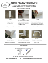
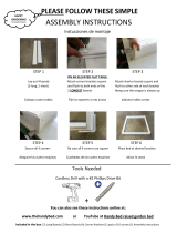
ASSEMBLY INSTRUCTIONS
PINNACLE PREPARATION
NOTE: Before beginning construction of
the Turbo Tower, several boards and rails
and rails must be cut or removed from
the Pinnacle.
1. Remove the top 2" x 4" board from the
front of the unit as indicated by removing
the screws at each joint.
2. Cut the 2" x 4" rail flush to the existing
upright as indicated. Remove the cut
board from the front of the unit as
indicated by removing the screws.
3. Remove the entire rail section of deck two
by removing the screws at the rail/post
joints.
4. Cut the 2" x 6" bottom support flush with
the existing 4" x 4" post as indicated.
Remove the carriage bolts and screws
from both pieces. NOTE: The section of
the bottom rail which is not shaded will be
re-used. Do not discard this section of
lumber.
5. Remove the carriage bolts and screws at
each end of the bottom 2" x 6" s as
indicated and remove.
6. Collect all lumber and hardware removed
and safely discard.
FIGURE 1
SAVE THIS PIECE OF LUMBER
GUARDE ESTE PEDAZO DE MADERA
CONSERVER CETTE PIÈCE DE BOIS

16
TOWER INSTALLATION
1. Reposition the bottom 2" x 6" x 38-1/4"
base board previously removed to the
back of the 4" x 4" posts. Counterbore
the front of the posts using a 1-1/8"
spade bit approximately 1/2" deep and
re-attach the board using two 5"
carriage bolts, wood loc washers,
washers and loc nuts.
2. Assemble the tower step as indicated in
Fig. 2A below using two 3" screws per
joint. Position the step assembly in the
opening as shown and attach to the unit
using two 3" screws on each side, both
top and bottom.
3. Attach the 2" x 6" x 91-1/2" and 2" x 6"
x 45-1/2" boards to the base of the unit
using four 3" screws per joint (two if
attaching to a 2" x 4" upright).
4. Using the existing bolt holes as a guide,
drill 3/8" holes through the previously
attached 2" x 6" base boards. Secure
each joint using a 5" carriage bolt, wood
loc washer, washer and loc nut.
5. Drill an additional hole through the
center upright and 2" x 6" base board
as indicated. Counterbore the 4" x 4"
approximately 1/2" deep at the hole
location. Secure the joint using a 5"
carriage bolt, wood loc washer, washer
and loc nut.
6. Attach the 2" x 6" x 40-1/4" base board
to the ends of the existing base boards
using two 3" screws per joint.
2" x 4" x 27-1/4"
2" x 4" x 17"
2" x 4" x 17"
FIGURE 2
FIGURE 2A
ASSEMBLY INSTRUCTIONS
2" x 6" x 40-1/4"
2" x 6" x 38-1/4"
(existing board)
2" x 6" x 91-1/2"
2" x 6" x 45-1/2"
12" to top
12" en la base
de arriba
12 po de la
partie supérieure

18
TOWER INSTALLATION (cont.)
7. Attach two 2" x 6" x 37-1/4" and one
2" x 6" x 32-3/4" spacer boards to the
unit as indicated in Fig. 3 using four 3"
screws per joint.
8. Attach the 2" x 6" x 90" and 2" x 6" x
45-1/2" boards to the top of the unit
using four 3" screws per joint.
9. Position two 4" x 4" posts to the
assembly as indicated. Attach at the
top and bottom using four 3" screws
per joint.
10. Attach 2" x 6" x 40-1/4" to the top of
the posts using four 3" screws per
joint.
11. Using the existing bolt holes as a
guide, drill 3/8" holes through the
previously attached 2" x 6" x 90" top
board. Secure each joint using a
5" carriage bolt, wood loc washer,
washer and loc nut.
12. Drill 3/8" holes through the remaining
2" x 6" and 4" x 4" joints as indicated.
Counterbore the 4" x 4" approximately
1/2" deep at the hole locations. Secure
each joint using a 5" carriage bolt,
wood loc washer, washer and loc nut.
FIGURE 3
ASSEMBLY INSTRUCTIONS
2" x 6" x 45-1/2"
2" x 6" x 40-1/4"
4" x 4" x 120"
4" x 4" x 120"
2" x 6" x 33-3/4"
(2) 2" x 6" x 37-1/4"
2" x 6" x 90"

20
DECK INSTALLATION
1. Attach two 2" x 6" x 45-1/2" deck
supports to the unit as indicated in
Fig. 4 using four 3" screws per joint.
NOTE: The tops of these boards
should be approximately 82-1/2" from
the ground and should be level.
2. Drill 3/8" holes through the 2" x 6"
and 4" x 4" joints of the deck supports
as indicated. Counterbore the
4" x 4" approximately 1/2" deep at
each hole location. Secure each joint
using a 5" carriage bolt, wood loc
washer, washer and loc nut.
3. Place 2" x 6" x 27-1/4" spacer board
between the deck supports and attach
using two 3" screws per joint. NOTE:
Do not allow screws to split the
surface of the 2" x 6" x 27-1/4" spacer .
If this occurs, back out screw and
reposition.
4. Place the 2" x 4" x 30-1/4" deck board
between the 4" x 4" posts as shown in
Fig. 5. Attach to the deck support
using two 3" screws per joint.
5. Place the 2" x 4" x 40-1/4" on the
supports as indicated in Fig. 5.
NOTE: The 2" x 4" x 40-1/4" deck
board should be tight against the
corresponding 4" x 4" posts and
should extend approximately 1-1/2"
past the edge of each post. Attach
using two 3" screws per joint.
6. Evenly space six 2" x 6" x 40-1/4"
boards between the previously
attached deck boards. NOTE: The
2" x 6" x 40-1/4" deck boards should
extend approximately 1-1/2" past the
edge of each post. Attach using two 3"
screws per joint.
ASSEMBLY INSTRUCTIONS
2" x 6" x 45-1/2"
2" x 6" x 45-1/2"
2" x 6" x 27-1/4"
2" x 6" x 40-1/4"
(6 total)
2" x 4" x 30-1/4"
2" x 4" x 40-1/4"
FIGURE 4
FIGURE 5
82-1/2" to ground
82-1/2" a la tierra
82 1/2 po jusqu’au sol

22
TOP RAIL INSTALLATION
1. Drill a 3/8" hole through the 4" x 4" x
36" boards (2 are required)
approximately 8" from the top and
bottom of each board. Counterbore
each hole 1/2" deep.
2. Position each 4" x 4" flush with the top
of the deck and existing posts as
indicated in Fig. 6. Mark the hole
locations on the posts and drill 3/8"
holes through the 4" x 4" posts at the
marked locations.
3. Align the holes of the 4" x 4" x 36"
boards and the posts and secure
using two 7" carriage bolts, wood loc
washers, washers and loc nuts per
board.
4. Attach a 2" x 4" x 45-1/2" bottom rail
support to each side of the deck using
four 3" screws per joint. The rail
supports should rest on existing deck
boards.
5. Evenly space five 5/4" x 6" x 36" rail
uprights in each opening as shown in
Fig. 7. Attach the uprights to the
supports using two 2" screws at the
top and bottom of each board.
6. Attach a 2" x 6" x 37-1/4" board to the
front of the tower using four 3" screws
per joint. NOTE: The top of the 2" x 6"
x 37-1/4" should be flush with the top
of the deck.
7. Attach a 2" x 4" x 37-1/4" directly
below the previously attached board
using four 3" screws per joint.
ASSEMBLY INSTRUCTIONS
FIGURE 6
FIGURE 7
2" x 4" x 45-1/2"
2" x 4" x 45-1/2"
4" x 4" x 36"
5/4" x 6" x 36"
5/4" x 6" x 36"
2" x 6" x 37-1/4"
2" x 4" x 37-1/4"
4" x 4" x 36"

24
BOTTOM RAIL INSTALLATION
1. Attach a 2" x 4" x 37-1/4" rail support
to the front of the tower using four 3"
screws per joint. NOTE: The top of the
rail support should be approximately
30" from the bottom of the unit.
2. Attach two 2" x 4" x 47" rail supports
to the sides of the tower as shown in
Fig. 8 using four 3" screws per joint.
3. Evenly space five 5/4" x 6" x 30" rail
uprights in each side opening as
shown in Fig. 8. Attach the uprights to
the supports using two 2" screws at
the top and bottom of each board.
4. Evenly space four 5/4" x 6" x 30" rail
uprights in front of the tower as shown
in Fig. 8. Attach the uprights to the
supports using two 2" screws at the
top and bottom of each board.
FINAL TOWER ASSEMBLY
1. Attach a 2" x 4" x 37-1/4" directly
beneath the existing 2" x 6" using four
3" screws per joint.
2. Attach the two remaining 2" x 4" x 27"
and two 2" x 6" x 27" boards as
shown using four evenly spaced 3"
screws.
ASSEMBLY INSTRUCTIONS
FIGURE 8
FIGURE 9
2" x 4" x 37-1/4"
2" x 4" x 47"
2" x 6" x 27"
2" x 4" x 27"
2" x 4" x 27"
5/4" x 6" x 30"
5/4" x 6" x 30"
2" x 4" x 37-1/4"
2" x 6" x 27"
30"

28
FIGURE 1
FIGURE 2
FIGURE 3
Entrance Section - 14 bolts
Sección de Entrada - 14 pernos
Section d’entrée - 14 boulons
flanged lip
labio levantado
bord relevé
flat lip
labio plano
bord plat
Exit Section - 13 bolts
Sección de salida-13 pernos
Section de sortie - 13 boulons
90° Section (2 are required) - 13 bolts each
Sección 90° (se requieren 2) - 13 pernos cada una
Section à 90° (2 requises) - 13 boulons chacune
loc nut
tuerca
écrou de blocage
washer arandela rondelle
washer arandela rondelle
3/4" bolt
3/4" perno
boulon de 3/4 po
ENTRANCE SECTION, 90° SECTION (2)
AND EXIT SECTION
NOTES:
• At least two individuals are needed to
assemble the Turbo Tube Slide.
• To aid in aligning holes when assembling
sections, insert a screwdriver through adjacent
holes to maintain hole alignment.
1. Identify each slide section as either (1), (2),
(3), (4), (5), or (6) as marked on the lip of each
piece.
2. Assemble entrance section using pieces (1) &
(2), two 90° sections using pieces (3) & (4),
and the exit section using pieces (3) & (5).
Join sections using a 3/4" hex head bolt, two
flat washers, and a loc nut at each hole
junction (FIGURES 1, 2 & 3). NOTE: Fasten
each loc nut finger tight until the entire slide is
assembled. Each time you join parts be sure
each flanged lip is mating with a flat lip.
ASSEMBLY INSTRUCTIONS

30
FIGURE 4
MOUNTING PANEL
1. Position the mounting panel as indicated in Fig. 4
(The stamped "T" should be at the top). The
panel should be centered horizontally and the
bottom of the opening should be approximately 1"
below the deck surface.
NOTE: The holes identified with arrows (Fig.4)
should be clear of any wood surface.
2. Hold the panel in position and mark all hole
locations. Remove panel.
3. Drill a 3/8" hole through the top support at the
locations indicated in Fig.5 (two holes are
required).
4. Drill pilot holes at the remaining hole locations
using a 1/8" drill bit.
NOTE: The pilot holes at each corner hole
location should be approximately 2" deep. The
remaining pilot holes should only be 1" deep.
5. Align the mounting panel to the previously
assembled entrance section (see Fig. 7, page
32). Attach the mounting panel to the entrance
section at the hole locations indicated in Fig. 4
using one 1" bolt, two washers and one loc nut
per hole as indicated in Figure 6.
NOTE: Hand tighten the loc nuts only.
FIGURE 5
FIGURE 6
1" from top of deck
1" de la parte de arriba de la cubierta
1 po du haut de la plate-forme
ASSEMBLY INSTRUCTIONS
loc nut
tuerca
écrou de
blocage
washer
arandela
rondelle
washer
arandela
rondelle
1" bolt
1" perno
boulon de 1 po

32
TUBE ASSEMBLY
1. Position the 90° section to the entrance section
so the seams line up. Rotate the section two
holes to the right (clockwise) and realign with the
holes of the entrance section (see FIGURE 7).
2. Insert a 3/4" bolt through a washer, through the
holes of slide sections, a second washer and
secure with a loc nut.
NOTE: Insert first bolt and continue in a
clockwise rotation. Do not skip holes. Hand
tighten the loc nuts only at this time.
3. Position the 90° section to the previously attached
section so the seams line up. Rotate the section
two holes to the left (counterclockwise) and
realign with the holes of the entrance section (see
FIGURE 8).
4. Insert a 3/4" bolt through a washer, through the
slide sections, a second washer and secure with
a loc nut. NOTE: Hand tighten the loc nuts only at
this time.
FIG.URE 7
FIGURE 8
Rotate seam
two holes to
the right
(clockwise)
Girar el
dobladillo de
los agujeros a
la derecha
Tourner le joint
de deux trous
vers la droite
(sens des
aiguilles d'une
montre)
Rotate seam two
holes to the left
(counterclockwise)
Girar el dobladillo
de los agujeros a la
izquierda
Tourner de deux
trous vers la
gauche (sens
contraire à celui
des aiguilles
d'une montre)
ASSEMBLY INSTRUCTIONS

34
TUBE ASSEMBLY (CONT.)
5. Position the exit section to the previously
attached sections so the seams line up.
Rotate the section two holes to the left
(counterclockwise) and realign with the
holes of the entrance section (see
FIGURE 9).
6. Insert a 3/4" bolt through a washer,
through the slide sections, a second
washer and secure with a loc nut.
NOTE: Hand tighten the loc nuts only at
this time.
7. Position the slide base to the slide
assembly as indicated in FIGURE 10.
8. Insert a 3/4" bolt through a washer,
through the slide sections, a second
washer and secure with a loc nut.
9. Tighten all of the bolts of the slide
sections securely at this time.
NOTE: Do not tighten the bolts of the
mounting plate at this time.
FIGURE. 9
FIGURE 10
Rotate seam two
holes to the left
(counterclockwise)
Girar el dobladillo
de los agujeros a la
izquierda
Tourner de deux
trous vers la
gauche (sens
contraire à celui
des aiguilles
d'une montre)
dimple
marke
encoche
dimple
marke
encoche
hole
perfore
trou
ASSEMBLY INSTRUCTIONS

36
MOUNTING SLIDE
1. The help of at least one other individual
will be required for mounting the slide.
2. Insert the 2-3/4" bolts through a washer,
through previously drilled 3/8" holes in the
upper rail of the unit (see FIGURE 11).
3. Carefully lift the slide assembly to the
opening of the unit. Place the mounting
panel/slide assembly on the 2-3/4" bolts
previously inserted (see FIGURE 11).
Place washers and loc nuts on the bolts
and hand tighten.
4. Adjust the mounting panel/slide assembly
until the holes of the mounting panel align
with the previously drilled pilot holes.
5. Attach the top corners of the mounting
panel/slide assembly first using a 2-1/2"
lag bolt and washer . Secure the
remainder of the panel/slide assembly to
the unit using 1-1/2" lag bolts and
washers at each open hole location (8 are
required).
6. Tighten the 2-3/4" bolts securely.
7. Attach the bottom corners of the mounting
panel/slide assembly using a 2-1/2" lag
bolt and washer.
SLIDE BASE
1. Remove approximately 3" of grade
directly beneath the base of the slide.
FIGURE 11
FIGURE 12
2-3/4" bolt
2-3/4" perno
boulon de 2-3/4 po
washer
arandela
rondelle
washer
arandela
rondelle
washer
arandela
rondelle
washer
arandela
rondelle
washer
arandela
rondelle
loc nut
tuerca
écrou de
blocage
loc nut
tuerca
écrou
de blocage
2-3/4" bolt
2-3/4" perno
boulon de 2-3/4 po
2-1/2" lag bolt
pernos de retraso de 2-1/2"
tire-fond de 2 1/2 po
1-1/2" lag bolt
pernos de retraso de 1-1/2"
tire-fond de 1 1/2 po
3"
ASSEMBLY INSTRUCTIONS

38
SUPPORT AND BRACKET ASSEMBLY
1. Position the slide bracket between the slide and
activity center (FIGURE 13). Remove
appropriate bolts from the slide (the fourth and
fifth bolts as indicated), Attach bracket to the
underside of the seam using the previously
removed hardware (FIGURE 13).
2. If necessary, move slide towards the activity
center until the slide bracket makes contact with
the unit. Using holes in the bracket (indicated by
arrows in FIGURE 13) as a guide, mark and
drill 1/8" pilot holes (1" deep). NOTE: You may
need to temporarily remove the slide bracket to
drill the pilot holes.
3. Re-attach bracket (if necessary) and secure it to
the unit using two 1-1/2" lag bolts .
4. Assemble the support base as shown in
FIGURE 14. NOTE: Use four 2" screws to
fasten the 2' x 4' x 9-1/4" boards and 3" screws
for remainder of assembly.
5. Attach the support bracket to the support base
using two 1-1/2" lag bolts (FIGURE 15).
NOTE: Pre-drill 1/8" pilot holes.
6. Place the support beneath the slide base and
determine its final position. NOTE: Slide
support should fit tightly beneath the slide to
assure proper support. Remove corresponding
nut and bolt, attach support to the slide as
indicated in FIGURE 16. Re-attach hardware.
7. Level grade at the bottom of the slide.
FIGURE 13
FIGURE 14
slide bracket
braqueta del resbaladero
support de glissoire
1-1/2" bolt
1-1/2" perno
boulon de 1-1/2 po
exit section
sección de salida
section de sortie
2" x 4" x 9-1/4"
2" x 4" x 7"
2" x 4" x 20"
2" x 4" x 20"
2" screws
tornillos de 2"
vis de 2 po
3" screws
tornillos de 3"
vis de 3 po
washer
arandela
rondelle
loc nuts
tuercas
écrous de
blocage
2" x 4" x 9-1/4"
FIGURE 16
ASSEMBLY INSTRUCTIONS
FIGURE15
1-1/2" lag bolts
pernos de retraso
de 1-1/2"
tire-fonds de 1 1/2po
support bracket
braqueta de soporte
ferrure de support

© PlayCore Inc. 2002 Printed In USA LA 5077
Impresso en EE.UU.
Imprimé aux États-Unis
FINAL ASSEMBLY
1. Ground Anchors are provided with this kit and must be installed at each corner of the Turbo Tower.
2. Screw a ground anchor into the ground near each 4" x 4" corner post of the tower until only the triangular head
remains (see FIGURES 17 and 18).
3. Insert a strap through the head of the anchor. Align holes of strap as illustrated and attach to the unit using one
1-1/2" lag bolt and washer per anchor.
ENSAMBLAJE FINAL
1. Anclas de tierra se proveen con este equipo y deben ser instaladas en cada esquina de la torre de turbo
2. Atornillar un ancla detierra a 4"X 4" en el poste de la esquina hasta que sólo quede la cabeza triangular .
3. Insertar una cuerda por el ancla. Alinear los agujeros como se ilustra y adhiera a la unidad usando un perno de
atrás de 1-1/2" y una arandela por ancla.
ASSEMBLAGE FINAL
1. Des pièces d’ancrage sont fournies avec cette unité et elles doivent être installées dans chacun des
coins de la tour Turbo (Turbo Tower).
2. Visser une pièce d’ancrage dans le sol près de chacun des montants de 4 po x 4 po de l’unité en ne laissant
dépasser que la tête triangulaire (voir les FIGURES 17 et 18).
3. Insérer une attache dans la tête triangulaire de la pièce d’ancrage. Aligner les orifices des attaches comme le
montre l’illustration et fixer chaque attache à l’unité en utilisant un tire-fond de 1 1/2 po et une rondelle par
pièce d’ancrage.
FIGURE 17
FIGURE 18
/