Page is loading ...

SmartTrak
®
100
Modbus
Instruction Manual
Modbus Device Specification for SmartTrak
®
Models: 100, 101, and 140
Mass Flow Meters & Controllers
Part Number: IM-100ModbusRev.V1
May 2013

GLOBAL SUPPORT LOCATIONS: WE ARE HERE TO HELP!
CORPORATE HEADQUARTERS
5 Harris Court, Building L Monterey, CA 93940
Phone (831) 373-0200 (800) 866-0200 Fax (831) 373-4402
www.sierrainstruments.com
EUROPE HEADQUARTERS
Bijlmansweid 2 1934RE Egmond aan den Hoef
The Netherlands
Phone +31 72 5071400 Fax +31 72 5071401
ASIA HEADQUARTERS
Second Floor Building 5, Senpu Industrial Park
25 Hangdu Road Hangtou Town
Pu Dong New District, Shanghai, P.R. China
Postal Code 201316
Phone: + 8621 5879 8521 Fax: +8621 5879 8586
IMPORTANT CUSTOMER NOTICE: OXYGEN SERVICE
Sierra Instruments, Inc. is not liable for any damage or personal injury, whatsoever, resulting from the use of Sierra Instruments standard
mass flow meters or controllers for oxygen gas. You are responsible for determining if this mass flow meter or controller is appropriate for
your oxygen application. You are responsible for cleaning the mass flow meter or controller to the degree required for your oxygen flow
application.
© COPYRIGHT SIERRA INSTRUMENTS 2013
No part of this publication may be copied or distributed, transmitted, transcribed, stored in a retrieval system, or translated into any
human or computer language, in any form or by any means, electronic, mechanical, manual, or otherwise, or disclosed to third parties
without the express written permission of Sierra Instruments. The information contained in this manual is subject to change without
notice.
TRADEMARKS
SmartTrak 100 Modbus™, SmartTrak®, and Dial-A-Gas® are trademarks of Sierra Instruments, Inc. Other product and company names
listed in this manual are trademarks or trade names of their respective manufacturers.

Warnings and Cautions
Note and Safety Information
We use caution and warning statements throughout this book to draw
your attention to important
information.
Warning!
Caution! / Note!
This statement appears with information that
is important to protect people and equipment
from damage. Pay very close attention to all
warnings that apply to your application.
This statement appears with information that is
important for protecting your equipment and
performance. Read and follow all cautions that
apply to your application.
Warning!
Agency approval for hazardous location installations varies between flow meter models. Consult the flow meter
nameplate for specific flow meter approvals before any hazardous location installation.
Warning!
All wiring procedures must be performed with the power off.
Warning!
To avoid potential electric shock, follow National Electric Code safety practices or your local code when wiring this unit
to a power source and to peripheral devices. Failure to do so could result in injury or death. All AC power connections must be in
accordance with published CE directives.
Warning!
Do not power the flow meter with the sensor remote (if applicable) wires disconnected. This could cause over-heating of the
sensors and/or damage to the electronics.
Warning!
Before attempting any flow meter repair, verify that the line is de-pressurized.
Warning!
Always remove main power before disassembling any part of the mass flow meter/controller.
Caution!
Before making adjustments to the device, verify the flow meter/controller is not actively monitoring or reporting to any
master control system. Adjustments to the electronics will cause direct changes to flow control settings.
Caution!
When using toxic or corrosive gases, purge the line with inert gas for a minimum of four hours at full gas flow
before installing the meter.
Caution!
The AC wire insulation temperature rating must meet or exceed 80°C (176°F).
Caution!
Printed circuit boards are sensitive to electrostatic discharge. To avoid damaging the board, follow these
precautions to minimize the risk of damage:
before handling the assembly, discharge your body by touching a grounded, metal object
handle all cards by their edges unless otherwise required
when possible, use grounded electrostatic discharge wrist straps when handling sensitive components
!
!

4
Receipt of System Components
When receiving a Sierra mass flow meter, carefully check the outside
packing
carton for
damage incurred in shipment. If the carton is damaged, notify the local carrier and submit a
report to the factory or distributor. Remove the packing slip and check that all ordered
components are present. Make sure any spare parts or accessories are not
discarded with
the packing material. Do not return any equipment to
the factory without first contacting
Sierra Customer Service
.
Technical Assistance
If you encounter a problem with your flow meter, review the configuration information for
each step of the installation, operation, and
setup procedures. Verify that your settings
and adjustments are consistent with factory recommendations. Installation and
troubleshooting information can be found in the SmartTrak
®
100 Series manual.
If the problem persists after following the troubleshooting procedures
outlined in the
SmartTrak 100 Series manual, contact Sierra Instruments by fax or by E-mail
(see inside
front cover). For urgent phone support you may call (800)
866-0200 or (831) 373-0200
between 8:00 a.m. and 5:00 p.m. PST. In
Europe, contact Sierra Instruments Europe at
+31
(0)72-5071400
. In the Asia-Pacific region, contact Sierra Instruments Asia at +
86-21-
58798521.
When contacting Technical Support, make sure to include this information:
The flow range, serial number, and Sierra order number (all
marked on
the meter nameplate)
The software version (visible at start up)
The problem you are encountering and any corrective action
taken
Application information (gas, pressure, temperature and piping
configuration)

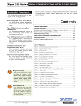
5
Table of Contents
Table of Contents ........................................................................................................................................... 5
Chapter 1: Introduction .................................................................................................................................. 7
Chapter 2: Electrical Connections ................................................................................................................ 8
RS-485 Connection ................................................................................................................................... 10
General 2-Wire Topology RS-485 Network ............................................................................................... 10
Daisy Chain Units ................................................................................................................................... 10
Cable......................................................................................................................................................... 10
Terminator ................................................................................................................................................. 10
Line Polarization ....................................................................................................................................... 11
Chapter 3: Communicating ......................................................................................................................... 12
Power Up ................................................................................................................................................... 12
Data Format Various Registers ................................................................................................................. 12
Modbus Registers Overview ...................................................................................................................... 13
Special-Modbus Set Up ............................................................................................................................. 14
Registers Explained ................................................................................................................................... 15
40001: Actual Flow ................................................................................................................................... 15
40003: Set Point ....................................................................................................................................... 15
40005 – 40008: Totalizer .......................................................................................................................... 15
40009: Valve Power .................................................................................................................................. 15
40015: Factory Full Scale ......................................................................................................................... 15
40017: User Full Scale .............................................................................................................................. 15
40019: Gas Span ...................................................................................................................................... 15
40034: Gas index ...................................................................................................................................... 16
40035: Valve Position Index ..................................................................................................................... 16
40036: Flow Unit Index ............................................................................................................................. 16
40037: Password ...................................................................................................................................... 17
40038: Input Set Point Index ..................................................................................................................... 17
40039: Analog Output Index ..................................................................................................................... 17
40040: Firmware Revision ........................................................................................................................ 17
40042: Device Type .................................................................................................................................. 17
40043 - 40046: Serial Number .................................................................................................................. 17
40047 - 40051: Tag ................................................................................................................................... 17
40052 – 40059: Gas Name 1 .................................................................................................................... 18
40060 – 40067: Gas Name 2 .................................................................................................................... 18
40068 – 40075: Gas Name 3 .................................................................................................................... 18
40076 – 40083: Gas Name 4 .................................................................................................................... 18
40084 – 40091: Gas Name 5 .................................................................................................................... 18
40092 – 40099: Gas Name 6 .................................................................................................................... 18
40100 – 40107: Gas Name 7 .................................................................................................................... 18
40108 – 40115: Gas Name 8 .................................................................................................................... 18
40116 – 40123: Gas Name 9 .................................................................................................................... 18
40124 – 40131: Gas Name 10 .................................................................................................................. 18
40132: Sensor Data .................................................................................................................................. 18
40133: Set Unit To Zero ............................................................................................................................ 18
40134: Reset Unit to Factory Default ........................................................................................................ 18
Special Modbus Set Up Registers ............................................................................................................. 18
44100: ID .................................................................................................................................................. 18
44101: Baud rate ...................................................................................................................................... 18
44102: Parity ............................................................................................................................................. 19
44103: TX delay ........................................................................................................................................ 19
44104: Reset unit ...................................................................................................................................... 19
Chapter 4: Bootloader .................................................................................................................................. 20
Introduction ................................................................................................................................................ 20
Getting Started .......................................................................................................................................... 20
Load Firmware (not typically required) ...................................................................................................... 21
Setup Firmware ......................................................................................................................................... 23
Default Firmware Settings ......................................................................................................................... 23

6
Quit ........................................................................................................................................................... 24
Trouble Shooting ....................................................................................................................................... 24

7
Chapter 1: Introduction
The SmartTrak 100 Modbus™ add-on module for Sierra Instruments’ SmartTrak Series 100, 101, and
140 gas flow measurement and control instruments.
A variety of features enable the integration of the SmartTrak into a Modbus network environment.
Among these features:
Access to all vital data
Sophisticated alarm system
Totalizer
SmartTrak functionality monitor
Sierra Instruments provides a graphic application to setup the SmartTrak 100 Modbus features (see
Appendix A). You can also access all the features in your application using Modbus compatible
software.
Important Tip!
To fully understand the SmartTrak 100 Modbus and its functions, it is recommended
that you also read the SmartTrak 100 Series instruction manual.
!

8
Chapter 2: Electrical Connections
All electrical connections are made on the left side of the SmartTrak 100 Modbus. The 15 Pin “P1”
connector is used for instrument power and analog signals. See SmartTrak 100 Manual. The D9
“COM” connector is used for the Modbus-RTU RS-485, and hard wired addressing.
Pin Configuration
The image below shows the name of the connector and the location of “pin 1.”
Figure 1 Pin Configuration
COM
Pin#
Function
1 (arrow)
RS-485 Shield
2
+24V Power
3
ID0 – selection bit
4
ID1 – selection bit
5
RS-485 – B
6
ID2 – selection bit
7
Ground
8
ID3 – selection bit
9
RS-485 – A
Warning!
Never connect a remote pilot module to the instrument when a SmartTrak 100
Modbus is mounted on it. Damage can occur.
COM
P1

9
P1
Pin#
Function
1.
Analog Ground/Output
2.
0-5 VDC Output (or 0-10, 1-5 VDC)
3.
Analog Ground/RS232
4.
Valve Override Purge
5.
Power Return (-)
6.
Power Input (+)
7.
RS-232 Transmit (out)
8.
Setpoint
9.
Not Used
10.
Analog Ground/Setpoint
11.
Reference Voltage
(5 VDC External Setpoint & Valve Purge)
12.
Valve Override Close
13.
RS-232 Receive (in)
14.
4-20 mA Output
15.
Not Used
Chassis (Earth) Ground
During power-up or reset the ID pins (TTL compatible) are scanned. These pins set the Modbus ID
address and will override the software set addresses.
Hardwired Network ID
ID3
ID2
ID1
ID0
Modbus ID
open
open
open
open
Internal ID
open
open
open
GND
1
open
open
GND
open
2
open
open
GND
GND
3
-
-
-
-
GND
GND
GND
GND
15
Instrument and SmartTrak 100 Modbus Power
The +24V (or optional PV1M 15VDC for meters) power and power return (GND) of the instrument
and the SmartTrak 100 Modbus are connected internally through the 15 pin P1 connector.
Power supply requirements (ripple should not exceed 100mV peak to peek.
Instrument
Type
Recommended Input Voltage
(regulated)
Minimum mA Requirement
M100 (all)
15-24 Vdc (±10%)
230
C100L
24 Vdc (±10%)
500
C100L-HP
24 Vdc (±10%)
800
C100M
24 Vdc (±10%)
800
C100H
24 Vdc (±10%)
1260
Note!
The pin out for P1 can be found in the SmartTrak 100 Series instruction manual.
Pins 1, 3, and 10 are connected together inside the instrument. Do not tie these
grounds together outside the instrument. Must have one connection per analog
ground. Recommended use listed.
!

10
RS-485 Connection
General 2-Wire Topology RS-485 Network
Figure 2 General 2-Wire Topology RS-485 Network
The “RS-485 – A” (also referred as ‘-‘) is connected with the D0 line. The “RS-485 – B” (also
referred as ‘+‘) is connected with the D1 line. The shield is connected to the common line of the
network. The use of line terminators depends on cable lengths and should be determined on site.
Daisy Chain Units
RS485 uses a daisy chain topology. It is important to avoid spur lines. Never connect a RS485 bus in a
star configuration.
When connecting multiple units the following COM pins are used for the link cable
1 (RS-485 shield)
5 (RS-485 – B, D1)
9 (RS-485 – A, D0)
Cable
It is recommended to use a twisted pair type of cable (reduces radiated and received EMI). Category 5
cables may be used to a maximum length of 600 meters. To operate at cable lengths of 1000 meter it is
advised to use AWG 26 or lower.
Terminator
Reflections in a transmission line can cause communication errors. To minimize the reflection it is
required to place terminator resistors at both ends of the cable. Never place a terminator resistor
somewhere along the cable; they need to be at the end of the bus. The use of line terminators depends
on cable lengths and should be determined on site. Typical values for terminator resistors are 120-150
ohm * (0.5 W).
Caution!
The SmartTrak 100 Modbus is equipped with an optical isolated RS-485 interface.
Don’t connect the RS-485 shield to the ground of the power supply unless the
isolated barrier isn’t required.
!

11
Line Polarization
In noise environments it may be necessary to polarize the lines to ensure that the receivers stay in a
constant state when no signal is present. The polarization must be implemented at one location for the
whole bus. The value for the pull up and pull down resistors is between 450 and 650 ohms * (a higher
value permits more devices to be connected to the bus).
Note
For specific resistor values and other bus requirements consult your RS-485
master’s documentation.
!

12
Chapter 3: Communicating
Once the SmartTrak 100 Modbus is wired to the network and powered up it is time to communicate
with it.
The default settings for the Modbus interface are as following:
ID code = 1-247 (or 1 – 15 depending on the COM 1 ID pin settings)
Baud rate = 19200
Parity = Even
Number of bits = 8
Stop bit = 1
Delay between receiving and transmitting = 2 ms
Changing the settings can be done through the boot loader (Chapter 7) or special registers.
Power Up
When powered up the green LED on top of the SmartTrak 100 Modbus enclosure will flash twice.
During this time it is possible to enter the boot loader (see Chapter 7on boot loader for more
information). After the flashing the red LED will light up indicating the initialization phase. During
this time data is retrieved from the SmartTrak and stored into the SmartTrak 100 Modbus memory.
There is no communication through Modbus possible at this stage.
Once all data is retrieved the red LED goes off and the green LED will start blinking as it receives data
from the instrument. Communication through Modbus is possible now.
If the communication with the instrument is lost for some reason, the SmartTrak 100 Modbus will try
to establish it again. During this phase the Modbus interface will not be active.
The red LED will light up every time a network message is received with the correct ID code.
Figure 3 LED’s showing the activities of the SmartTrak 100 Modbus™
Data Format Various Registers
32 bit float (Real): IEEE 754 floating point, low/high word order
BCD encoded: hex encoded decimal values f.i. 0x89 = decimal 89
8 & 16 bit integer: unsigned integer values
16 bits ASCII: ASCII encoded characters, high word = 1
st
character. 0x4944 = “ID”

13
Modbus Registers Overview
PDU
Address
Register
Description
Read/Write
Data type
No. registers
Dynamic Data
$00
40001
Actual flow - low
word
R
32 bits real
2
$01
40002
Actual flow - high
word
$02
40003
Set point - low word
R/W
32 bits real
2
$03
40004
Set point - high word
$04
40005
Totalizer3,4
R/W (Reset)
BCD
encoded
4
$05
40006
Totalizer1,2
R
$06
40007
Totalizer7,8
R
$07
40008
Totalizer5,6
R
$08
40009
Valve power
R
16 bits int.
1
$09
40010
Analog CH0
R
16 bits int.
1
$0A
40011
Analog CH1
R
16 bits int.
1
$0B
40012
Digital Data - IN
R
16 bits int.
1
$0C
40013
Digital Data - OUT
R/W
16 bits int.
1
$0D
40014
Alarm status
R/W
16 bit int.
1
Settings
$0E
40015
Factory f.s – low word
R
32 bits real
2
$0F
40016
Factory f.s – high
word
$10
40017
User f.s – low word
R/W
32 bits real
2
$11
40018
User f.s – high word
$12
40019
Gas span – low word
R/W
32 bits real
2
$13
40020
Gas span – high word
$21
40034
Gas index
R/W
8 bits int.
1
$22
40035
Valve position index
R/W
8 bits int.
1
$23
40036
Flow unit index
R/W
8 bits int.
1
$24
40037
Password
R/W
16 bits int.
1
$25
40038
Input set point index
R/W
8 bits int.
1
$26
40039
Analog output index
R/W
8 bits int.
1
Static Data
$27
40040
Device firm rev – low
word
R
32 bits real
2
$28
40041
Device firm rev – high
word
$29
40042
Device type
R
16 bits
ASCII
1
$2A
40043
Serial number – char
1,2
R
16 bits
ASCII
4
$2B
40044
Serial number – char
3,4
$2C
40045
Serial number – char
5,6
$2D
40046
Serial number – char
7,8
$2E
40047
Tag number - char 1,2
R
16 bits
ASCII
5
$2F
40048
Tag number - char 3,4
$30
40049
Tag number - char 5,6
$31
40050
Tag number - char 7,8
$32
40051
Tag number - char
9,10

14
$33
40052
Gas 1 – char 1,2
R
16 bits
ASCII
8
$3A
40059
Gas 1 – char 15,16
$3B
40060
Gas 2 – char 1,2
R
16 bits
ASCII
8
$42
40067
Gas 2 – char 15,16
$43
40068
Gas 3 – char 1,2
R
16 bits
ASCII
8
$4A
40075
Gas 3 – char 15,16
$4B
40076
Gas 4 – char 1,2
R
16 bits
ASCII
8
$52
40083
Gas 4 – char 15,16
$53
40084
Gas 5 – char 1,2
R
16 bits
ASCII
8
$5A
40091
Gas 5 – char 15,16
$5B
40092
Gas 6 – char 1,2
R
16 bits
ASCII
8
$62
40099
Gas 6 – char 15,16
$63
40100
Gas 7 – char 1,2
R
16 bits
ASCII
8
$6A
40107
Gas 7 – char 15,16
$6B
40108
Gas 8 – char 1,2
R
16 bits
ASCII
8
$72
40115
Gas 8 – char 15,16
$73
40116
Gas 9 – char 1,2
R
16 bits
ASCII
8
$7A
40123
Gas 9 – char 15,16
$7B
40124
Gas 10 – char 1,2
R
16 bits
ASCII
8
$82
40131
Gas 10 – char
15,16
$83
40132
Sensor data
R
8 + 8 bit int.
1
$84
40133
Set unit to zero
R/W ($A5)
8 bits int.
1
$85
40134
Reset unit to factory
default
R/W ($A5)
8 bits int.
1
Special-Modbus Set Up
PDU
Address
Register
Description
Read/Write
Type
No. registers
$1003
44100
ID (1-247)
R/W
16 bit int.
1
$1004
44101
Baud rate
1 = 4800, 2 = 9600
3 = 19K2, 4 = 38K4
5 = 57K6
R/W
16 bit int.
1
$1005
44102
Parity
1=none, 2=odd, 3=even
R/W
16 bit int.
1
$1006
44103
TX delay (milliseconds)
R/W
16 bit int.
1
$1007
44104
Reset unit:
Read value from this
R/W
16 bit int.
1

15
register and write it back.
This will reset the unit
Registers Explained
The registers are divided into four groups. The first group (40001 – 40014) represents the dynamic
data. This group changes the most. The second group (40015 – 40039) contains the settings from the
instrument and SmartTrak 100 Modbus specific settings. The third group contains static data about the
instruments. The last group (44100 – 44104) contains special functions to change the Modbus settings
while the unit is in the network.
Registered Descriptions
40001: Actual Flow
The actual flow as measured by the instrument.
40003: Set Point
When using a controller the set point is shown. Writing to this register will set the set point. When a
set point is entered which is beyond the full scale of the instrument then the set point will be changed
automatically to the full scale value
40005 – 40008: Totalizer
Totalizer value BCD encoded. The first two registers are the value left of the decimal point. The last
two registers represent the value behind the decimal point.
Example:
40005 = 0x0010
40006 = 0x1204
40007 = 0x1654
40008 = 0x4500
Total = 12040010. 45001654
40009: Valve Power
Value representing the power injected into the value (when using a controller). The value will range
between 0 and 3200 (4095 when purging the valve).
40015: Factory Full Scale
Factory full scale value of the instrument
40017: User Full Scale
The user full scale value allows you to re-range the instrument. Any value between 50% and 100% of
the factory full scale is allowed. The new value will also redefine the analog outputs of the instrument
(when used). The 20mA/5 Vdc will represent the new full scale value.
40019: Gas Span
The gas span value allows you to adjust the 100% calibration point in the field. This is a correction
factor, factory set to 1.000. This factor has an acceptable range of .500 to 2.00. This value will be
returned to 1.000 if factory defaults are reset.

16
40034: Gas index
Value shows which gas is selected on the instrument. Value can range between 1 and 10. This specific
index can be customizing when ordering. The default list is:
Value
Gas
1
Air
2
Argon (Ar)
3
Carbon Dioxide
(CO2)
4
Carbon Monoxide
(CO)
5
Methane (CH4)
6
Helium (He)
7
Hydrogen (H2)
8
Oxygen (O2)
9
Nitrogen (N2)
10
Nitrous Oxide (N20)
40035: Valve Position Index
Valve position index is the mode at which the valve of the controller will operate. The table shows the
available values:
Value
Mode
1
Automatic
2
Closed
3
Purge
40036: Flow Unit Index
The value indicates the selected flow unit on the instrument. The table shows the available values:
Value
Unit
1
Scc/s
2
Scc/m
3
Scc/h
4
Ncc/s
5
Ncc/m
6
Ncc/h
7
SCF/s
8
SCF/m
9
SCF/h
10
NM3/s
11
NM3/m
12
NM3/h
13
SM3/s
14
SM3/m
15
SM3/h
16
Sl/s
17
Sl/m
18
Sl/h
19
Nl/s
20
Nl/m
21
Nl/h
22
g/s
23
g/m
24
g/h
25
Kg/s

17
26
Kg/m
27
Kg/h
28
Lb/s
29
Lb/m
30
Lb/h
40037: Password
Current password in the instrument. This password doesn’t affect the SmartTrak 100 Modbus™.
40038: Input Set Point Index
Value indicates the source for the set point. The table shows the available values:
Value
Source
1
Digital (Modbus in this case)
2
0 – 5 volts
3
0 – 10 volts
4
1 – 5 volts
5
4 – 20 mA
6
0 – 20 mA
40039: Analog Output Index
Analog output index is the value which indicates the current selected analog output of the instrument.
The table shows the available values:
Value
Output Option
1
0 – 5 Vdc / 4 – 20 mA
2
0 – 10 Vdc / 4 – 20 mA
3
1 – 5 Vdc / 4 – 20 mA
4
0 – 5 Vdc / 0 – 20 mA
5
0 – 10 Vdc / 0 – 20 mA
6
1 – 5 Vdc / 0 – 20 mA
40040: Firmware Revision
Firmware revision number of the instrument
40042: Device Type
There are two characters indication the type of instrument attached to the SmartTrak 100 Modbus™.
The first character (high byte) indicates the version number of the Smart-Trak®. The second character
(low byte) indicates if a meter ‘M’ or controller ‘C’ is attached.
Examples:
‘2M’ = Current SmartTrak - Meter ;
‘1C’ = Obsolete SmartTrak -Controller (serial numbers lower the 125,000)
40043 - 40046: Serial Number
Serial number of the instrument expressed as an eight character string.
40047 - 40051: Tag
Tag (or label) string which is set in the SmartTrak 100 Modbus™. The tag can only be set in boot
loader mode and can be used f.i. to identify the instrument or its location.
Caution!
Select RS-232 as source when the set point needs to be controlled through the
network.
!

18
40052 – 40059: Gas Name 1
40060 – 40067: Gas Name 2
40068 – 40075: Gas Name 3
40076 – 40083: Gas Name 4
40084 – 40091: Gas Name 5
40092 – 40099: Gas Name 6
40100 – 40107: Gas Name 7
40108 – 40115: Gas Name 8
40116 – 40123: Gas Name 9
40124 – 40131: Gas Name 10
Gas table present in the instrument.
40132: Sensor Data
Sensor data from the instrument. The high byte shows the bridge voltage and the low byte shows the
bridge current.
40133: Set Unit To Zero
Writing the value 0xA5 to this register will zero the instrument. Make sure there is zero flow at your
application pressure before using this command. 40134 below will return the unit back to the factory
default zero.
40134: Reset Unit to Factory Default
Writing the value 0xA5 to this register will reset all your custom settings to factory defaults. The zero
value and gas span values are cleared.
Special Modbus Set Up Registers
The Modbus settings for the SmartTrak 100 Modbus can be altered while it is connected to the
network. Through special registers it is possible to change the settings. The settings can be changed
but will not become active until a special write is performed.
44100: ID
The ID code as stored in memory is shown. The ID code set through the ID pins on P1 is not shown.
Any value between 1 and 255 can be used.
44101: Baud rate
Value
Baud rate
1
4800
2
9600
3
19K2
4
38K4
5
57K6

19
44102: Parity
Value
Parity
1
None
2
Odd
3
Even
44103: TX delay
The value in this register will tell the SmartTrak 100 Modbus to wait a number of milliseconds before
starting to transmit the reply to the master.
Delay time = value x 1ms
44104: Reset unit
Writing back the value read from this register will trigger two events:
1. The values entered for the ID code, baud rate, parity and TX delay will be stored in memory
(making them permanent)
2. The SmartTrak 100 Modbus will perform a power-up reset reading the new settings
The new settings are now active. The new settings will not be stored unless the correct value is written
to this register. When the settings are changed and a manual reset is performed then the old settings
will be used.

20
Chapter 4: Bootloader
Introduction
This chapter describes how the boot loader is used. The boot loader makes it possible to set up
applications and download firmware using a simple terminal program and a serial connection.
Getting Started
In order to use the Bootloader, a PC is needed which is equipped with an RS-485 interface or an
external converter connected to the RS-232 port.
Connect the RS-485 interface of the SmartTrak 100 Modbus to the RS-485 interface of the PC. On
the PC start a simple terminal program like HyperTerminal.
Start HyperTerminal from windows and select the com port to which the RS-485 interface is
connected. Use the following settings:
Baud rate : 9600
Number of bits : 8
Parity : N
Stop bits : 1
Flow Control :None
The boot loader will only be active during the first 2 seconds after a power-up or reset. During power-
up (or reset) the green LED will blink twice before executing the application. To enter the boot loader,
follow the next steps:
1. Power up the unit
2. In HyperTerminal press the enter key within 2 seconds of power up (any other key will
terminate the boot loader and will start the application)
When the boot loader is activated successfully the green LED will stay on. The following menu will
be presented on the screen:
/