Supermicro Super Microcloud 5037MR-H8TRF User manual
- Category
- Server barebones
- Type
- User manual
This manual is also suitable for

SUPER
SUPERSERVER
Super Microcloud
TM
5037MR-H8TRF
®
USER’S MANUAL
Revision 1.0

The information in this User’s Manual has been carefully reviewed and is believed to be accurate.
The vendor assumes no responsibility for any inaccuracies that may be contained in this document,
makes no commitment to update or to keep current the information in this manual, or to notify any
person or organization of the updates. Please Note: For the most up-to-date version of this
manual, please see our web site at www.supermicro.com.
Super Micro Computer, Inc. ("Supermicro") reserves the right to make changes to the product
described in this manual at any time and without notice. This product, including software and docu-
mentation, is the property of Supermicro and/or its licensors, and is supplied only under a license.
Any use or reproduction of this product is not allowed, except as expressly permitted by the terms
of said license.
IN NO EVENT WILL SUPERMICRO BE LIABLE FOR DIRECT, INDIRECT, SPECIAL, INCIDENTAL,
SPECULATIVE OR CONSEQUENTIAL DAMAGES ARISING FROM THE USE OR INABILITY TO
USE THIS PRODUCT OR DOCUMENTATION, EVEN IF ADVISED OF THE POSSIBILITY OF
SUCH DAMAGES. IN PARTICULAR, SUPERMICRO SHALL NOT HAVE LIABILITY FOR ANY
HARDWARE, SOFTWARE, OR DATA STORED OR USED WITH THE PRODUCT, INCLUDING THE
COSTS OF REPAIRING, REPLACING, INTEGRATING, INSTALLING OR RECOVERING SUCH
HARDWARE, SOFTWARE, OR DATA.
Any disputes arising between manufacturer and customer shall be governed by the laws of Santa
Clara County in the State of California, USA. The State of California, County of Santa Clara shall
be the exclusive venue for the resolution of any such disputes. Super Micro's total liability for all
claims will not exceed the price paid for the hardware product.
FCC Statement: This equipment has been tested and found to comply with the limits for a Class A
digital device pursuant to Part 15 of the FCC Rules. These limits are designed to provide reasonable
protection against harmful interference when the equipment is operated in a commercial environ-
ment. This equipment generates, uses, and can radiate radio frequency energy and, if not installed
and used in accordance with the manufacturer’s instruction manual, may cause harmful interference
with radio communications. Operation of this equipment in a residential area is likely to cause harmful
interference, in which case you will be required to correct the interference at your own expense.
California Best Management Practices Regulations for Perchlorate Materials: This Perchlorate warn-
ing applies only to products containing CR (Manganese Dioxide) Lithium coin cells. “Perchlorate
Material-special handling may apply. See www.dtsc.ca.gov/hazardouswaste/perchlorate”
WARNING: Handling of lead solder materials used in this
product may expose you to lead, a chemical known to the
State of California to cause birth defects and other repro-
ductive harm.
Manual Revision 1.0
Release Date: June 28, 2012
Unless you request and receive written permission from Super Micro Computer, Inc., you may not
copy any part of this document.
Information in this document is subject to change without notice. Other products and companies
referred to herein are trademarks or registered trademarks of their respective companies or mark
holders.
Copyright © 2012 by Super Micro Computer, Inc.
All rights reserved.
Printed in the United States of America

Preface
About This Manual
This manual is written for professional system integrators and PC technicians. It
provides information for the installation and use of the SuperServer 5037MR-H8TRF.
Installation and maintenance should be performed by experienced technicians only.
The SuperServer 5037MR-H8TRF is an 8-node, Microcloud
TM
server system based
on the SC938BH-R1K62B 3U chassis and eight X9SRD-F motherboards.
Manual Organization
Chapter 1: Introduction
The fi rst chapter provides a checklist of the main components included with the
system and describes the main features of the Super X9SRD-F motherboard and
the SC938BH-R1K62B chassis.
Chapter 2: Server Installation
This chapter describes the steps necessary to install the server into a rack and
check out the server confi guration prior to powering up the system. If your server
was ordered without the processor and memory components, this chapter will refer
you to the appropriate sections of the manual for their installation.
Chapter 3: System Interface
Refer to this chapter for details on the system interface, which includes the functions
and information provided by the control panel on the chassis as well as other LEDs
located throughout the system.
Chapter 4: System Safety
You should thoroughly familiarize yourself with this chapter for a general overview
of safety precautions that should be followed when installing and servicing the
SuperServer 5037MR-H8TRF.
iii
Preface

SUPERSERVER 5037MR-H8TRF User's Manual
iv
Chapter 5: Advanced Motherboard Setup
Chapter 5 provides detailed information on the X9SRD-F motherboard, including the
locations and functions of connectors, headers and jumpers. Refer to this chapter
when adding or removing processors or main memory and when reconfi guring the
motherboard.
Chapter 6: Advanced Chassis Setup
Refer to Chapter 6 for detailed information on the SC938BH-R1K62B 3U server
chassis. You should follow the procedures given in this chapter when installing,
removing or reconfi guring drives and when replacing system power supply units
and cooling fans.
Chapter 7: BIOS
The BIOS chapter includes an introduction to BIOS and provides detailed informa-
tion on running the CMOS Setup Utility.
Appendix A: BIOS POST Codes
Appendix B: System Specifi cations

v
Preface
Notes

vi
Table of Contents
Chapter 1 Introduction
1-1 Overview ......................................................................................................... 1-1
1-2 Motherboard Features ..................................................................................... 1-2
Processors ...................................................................................................... 1-2
Memory ........................................................................................................... 1-2
SATA .............................................................................................................. 1-2
Rear I/O Ports ................................................................................................. 1-2
Graphics .......................................................................................................... 1-2
IPMI ................................................................................................................. 1-3
Other Features ................................................................................................ 1-3
1-3 Server Chassis Features ................................................................................ 1-4
System Power ................................................................................................. 1-4
Front Control Panel ......................................................................................... 1-4
Cooling System ............................................................................................... 1-4
1-4 Contacting Supermicro .................................................................................... 1-5
Chapter 2 Server Installation
2-1 Overview ......................................................................................................... 2-1
2-2 Unpacking the System .................................................................................... 2-1
2-3 Preparing for Setup ......................................................................................... 2-1
Choosing a Setup Location ............................................................................. 2-2
Rack Precautions ............................................................................................ 2-2
Server Precautions .......................................................................................... 2-2
Rack Mounting Considerations ....................................................................... 2-3
Ambient Operating Temperature ................................................................ 2-3
Reduced Airfl ow ......................................................................................... 2-3
Mechanical Loading ................................................................................... 2-3
Circuit Overloading ..................................................................................... 2-3
Reliable Ground ......................................................................................... 2-3
2-4 Installing the System into a Rack ................................................................... 2-4
Identifying the Sections of the Rack Rails ...................................................... 2-4
Locking Tabs ................................................................................................... 2-5
Releasing the Inner Rail ................................................................................. 2-5
Installing The Inner Rails on the Chassis ....................................................... 2-6
Installing the Outer Rails on the Rack ............................................................ 2-7
Standard Chassis Installation ......................................................................... 2-8
Optional Quick Installation Method ................................................................. 2-9
SUPERSERVER 5037MR-H8TRF User's Manual

vii
Table of Contents
2-5 Checking the Motherboard Setup ................................................................. 2-10
2-6 Preparing to Power On ................................................................................. 2-12
Chapter 3 System Interface
3-1 Overview ......................................................................................................... 3-1
3-2 Control Panel Buttons ..................................................................................... 3-1
Power Button/LED ........................................................................................... 3-1
3-3 LEDs ................................................................................................................ 3-2
Power Failure LED .......................................................................................... 3-2
3-4 Hard Drive Carrier LEDs ................................................................................. 3-3
3-5 Node LEDs ...................................................................................................... 3-3
Power Button and LED ................................................................................... 3-4
UIO Button and LED ....................................................................................... 3-4
Failure LED ..................................................................................................... 3-4
Chapter 4 System Safety
4-1 Electrical Safety Precautions .......................................................................... 4-1
4-2 General Safety Precautions ............................................................................ 4-2
4-3 ESD Precautions ............................................................................................. 4-3
4-4 Operating Precautions .................................................................................... 4-4
Chapter 5 Advanced Motherboard Setup
5-1 Handling the Motherboard .............................................................................. 5-1
Precautions ..................................................................................................... 5-1
Unpacking ....................................................................................................... 5-2
5-2 Motherboard Installation .................................................................................. 5-2
5-3 Connecting Cables .......................................................................................... 5-2
5-4 I/O Ports .......................................................................................................... 5-2
5-5 Installing the Processor and Heatsink ............................................................ 5-3
Installing an LGA 2011 Processor ................................................................... 5-3
Installing a CPU Heatsink ............................................................................... 5-6
5-6 Installing Memory ............................................................................................ 5-7
How to Install Memory .................................................................................... 5-7
Memory Support .............................................................................................. 5-7
Installing and Removing DIMMs ..................................................................... 5-8
Memory Population Guidelines ....................................................................... 5-9
5-7 Adding PCI Add-On Cards .............................................................................. 5-9
5-8 Motherboard Details .......................................................................................5-11
X9SRD-F Quick Reference ........................................................................... 5-12
5-9 Connector Defi nitions ................................................................................... 5-13
5-10 I/O Port Defi nitions ....................................................................................... 5-14

viii
5-11 Jumper Settings ............................................................................................ 5-15
5-12 Onboard Indicators ........................................................................................ 5-18
5-13 SATA Drive Connections ............................................................................... 5-19
5-14 Installing Software ......................................................................................... 5-19
Supero Doctor III ........................................................................................... 5-20
Chapter 6 Advanced Chassis Setup
6-1 Static-Sensitive Devices .................................................................................. 6-1
Precautions ..................................................................................................... 6-1
6-2 Removing the Chassis Cover ......................................................................... 6-2
6-3 Corresponding Nodes, Fans and Hard Drives ................................................ 6-3
6-4 Removing and Installing Hard Drives ............................................................. 6-4
6-5 Removing and Installing the Backplane .......................................................... 6-7
Removing the Backplane and Fan Bracket Assembly .................................... 6-7
Removing the Backplane from the Fan Bracket ............................................. 6-8
Installing the Backplane onto the Fan Bracket ............................................... 6-9
Installing the Backplane and Fan Bracket Assembly .................................... 6-10
6-6 Removing and Installing Motherboard Nodes ................................................6-11
6-7 Installing an Air Shroud ................................................................................. 6-12
6-8 System Fans ................................................................................................. 6-13
6-9 Power Supply ................................................................................................ 6-14
Power Supply Replacement .......................................................................... 6-14
Chapter 7 BIOS
7-1 Introduction ...................................................................................................... 4-1
Starting BIOS Setup Utility .............................................................................. 4-1
How To Change the Confi guration Data ......................................................... 4-1
How to Start the Setup Utility ......................................................................... 4-2
7-2 Main Setup ...................................................................................................... 4-2
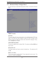
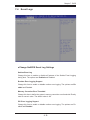
7-3 Advanced Setup Confi gurations...................................................................... 4-4
7-4 Event Logs .................................................................................................... 4-19
7-5 IPMI Settings ................................................................................................. 4-21
7-6 Boot Settings ................................................................................................. 4-23
7-7 Security Settings ........................................................................................... 4-25
7-8 Save & Exit ................................................................................................... 4-26
Appendix A POST Error Beep Codes
Appendix B System Specifi cations
SUPERSERVER 5037MR-H8TRF User's Manual

Chapter 1
Introduction
1-1 Overview
The SuperServer 5037MR-H8TRF is an eight node, Microcloud
TM
server system
comprised of two main subsystems: the SC938BH-R1K62B 3U chassis and eight
X9SRD-F motherboards. Please refer to our web site for information on operating
systems that have been certifi ed for use with the 5037MR-H8TRF (www.supermicro.
com).
In addition to the motherboard and chassis, various hardware components have
been included with the 5037MR-H8TRF, as listed below:
• Four chassis fans (FAN-0133L4)
• One passive heatsink, each node (SNK-P0047PS+)
• One air shroud, each node (MCP-310-93803-0B)
• One riser card, each node (RSC-RR1U-E8)
• SATA Accessories
One SATA backplane (BPN-SAS-938H)
Sixteen hot-swap hard drive carriers (MCP-220-00094-0B)
• One rail kit (MCP-290-00053-0N)
Chapter 1: Introduction
1-1

1-2
SUPERSERVER 5037MR-H8TRF User's Manual
1-2 Motherboard Features
The 5037MR-H8TRF includes a total of eight X9SRD-F single processor moth-
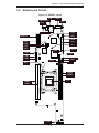
erboards, which are based on the Intel C602J PCH chipset. Below are the main
features of the X9SRD-F. (See Figure 1-1 for a block diagram of the chipset).
Processors
Each X9SRD-F supports a single Intel E5-2600 Series processor in an LGA 2011
socket. Please refer to the motherboard description pages on our web site for a
complete listing of supported processors (www.supermicro.com).
Memory
The X9SRD-F has four DIMM slots that can support up to 128 GB of ECC LV/LR/R/
UDIMM DDR3-1600/1333/1066/800 memory. This equates to a maximum of 1024
GB for the system. Memory modules of the same size and speed should be used.
See Chapter 5 for details.
SATA
A SATA controller is integrated into the chipset to provide a six-port SATA subsystem.
Two of these are for SATA 3.0 (ports SATA0/1) and the rest support SATA 2.0. The
SATA drives are hot-swappable units.
Note: The operating system you use must have RAID support to enable the hot-
swap capability and RAID function of the SATA drives.
Rear I/O Ports
The rear I/O panel includes one KVM connector, an IPMI port, a power LED and
buttons for UID (Unit Identifi cation) and power.
Graphics
There is no onboard graphics controller on the X9SRD-F. A VGA port is included
on the KVM connector.

1-3
Chapter 1: Introduction
IPMI
IPMI (Intelligent Platform Management Interface) is a hardware-level interface speci-
fi cation that provides remote access, monitoring and administration for Supermicro
server platforms. IPMI allows server administrators to view a server’s hardware
status remotely, receive an alarm automatically if a failure occurs, and power cycle
a system that is non-responsive.
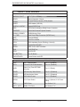
Other Features
Other onboard features that promote system health include onboard voltage moni-
tors, a chassis intrusion header, auto-switching voltage regulators, chassis and CPU
overheat sensors, virus protection and BIOS rescue.
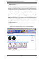
Figure 1-1. Intel C602J Chipset:
System Block Diagram
Note: This is a general block diagram. See Chapter 5 for details.
TPM1.2
Header
PCH
600MB/s
SATA-III
LPC
HEALTH
INFO
LPC I/O
FLASH
SPI 64Mb
NCT6776F
SPI
2 SATA PORTS (BP)
2 SATA PORTS (BP)
VGA
RTL8201F
PHY
HERMON WPCM450
WINBOND
PCI32
/
8GT/s
PCIe x8 SLOT (Micro LP)
PCIe3.0_x8
PCIe3.0_x8
PCIe x8 SLOT
8GT/s
DDR3 (CHD)
DDR3 (CHC)
DIMMC
Up to *1600/1866MHz
DIMMD
5GT/s
x4 DMI II
*Sandy Bridge EP
DDR3 (CHA)
Patsburg-J
DIMMA
DDR3 (CHB)
DIMMB
300MB/s
SATA-II
USB Header (2 ports)
USB2.0
480Mbps
(*:Default)
Ivy Bridge
Up to *1600/1866MHz
Up to *1600/1866MHz
Up to *1600/1866MHz
JKVM
USB2.0
480Mbps
USB x 2
RMII
COM1
FLASH
SPI 128Mb
(For BMC update BIOS only)
2 SATA PORTS (MB)
SATA-II
300MB/s
USB2.0
480Mbps

1-4
SUPERSERVER 5037MR-H8TRF User's Manual
1-3 Server Chassis Features
The following is a general outline of the main features of the SC938BH-R1K62B
server chassis.
System Power
The SC938BH-R1K62B features a redundant (two separate power modules) 1620W
high-effi ciency power supply. This power redundancy feature allows you to replace
a failed power supply without shutting down the system.
Front Control Panel
The control panel on the 5037MR-H8TRF features a power button/LED, a power fail
LED and eight LEDs to indicate the status of each node in the system.
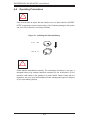
Cooling System
The SC938BH-R1K62B chassis includes four 8-cm fans located behind the back-
plane. Each fan is associated with and controlled by two nodes. Each node also
has an air shroud to channel the airfl ow from the system fans to effi ciently cool the
components that generate the most heat. See Chapter 6 for details.

1-5
Chapter 1: Introduction
1-4 Contacting Supermicro
Headquarters
Address: Super Micro Computer, Inc.
980 Rock Ave.
San Jose, CA 95131 U.S.A.
Tel: +1 (408) 503-8000
Fax: +1 (408) 503-8008
Email: [email protected] (General Information)
[email protected] (Technical Support)
Web Site: www.supermicro.com
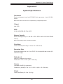
Europe
Address: Super Micro Computer B.V.
Het Sterrenbeeld 28, 5215 ML
's-Hertogenbosch, The Netherlands
Tel: +31 (0) 73-6400390
Fax: +31 (0) 73-6416525
Email: [email protected] (General Information)
[email protected] (Technical Support)
[email protected] (Customer Support)
Asia-Pacifi c
Address: Super Micro Computer, Inc.
4F, No. 232-1, Liancheng Rd.
Chung-Ho Dist., New Taipei City 235
Taiwan
Tel: +886-(2) 8226-3990
Fax: +886-(2) 8226-3991
Web Site: www.supermicro.com.tw
Technical Support:
Email: [email protected]
Tel: 886-2-8228-1366, ext.132 or 139

1-6
SUPERSERVER 5037MR-H8TRF User's Manual
Notes

Chapter 2: Server Installation
2-1
Chapter 2
Server Installation
2-1 Overview
This chapter provides a quick setup checklist to get your 5037MR-H8TRF up and
running. Following these steps in the order given should enable you to have the
system operational within a minimum amount of time. This quick setup assumes
that your system has come to you with the processors and memory preinstalled. If
your system is not already fully integrated with a motherboard, processors, system
memory etc., please turn to the chapter or section noted in each step for details on
installing specifi c components.
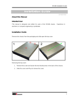
2-2 Unpacking the System
You should inspect the box the 5037MR-H8TRF was shipped in and note if it was
damaged in any way. If the server itself shows damage you should fi le a damage
claim with the carrier who delivered it.
Decide on a suitable location for the rack unit that will hold the 5037MR-H8TRF.
It should be situated in a clean, dust-free area that is well ventilated. Avoid areas
where heat, electrical noise and electromagnetic fi elds are generated. You will also
need it placed near a grounded power outlet. Be sure to read the Rack and Server
Precautions in the next section.
2-3 Preparing for Setup
The 5037MR-H8TRF may have come with hardware to mount the system into
a server rack. If mounting to a rack with the rail kit, follow the steps in the order
given to complete the installation process in a minimum amount of time. Please
read this section in its entirety before you begin the installation procedure outlined
in the sections that follow.

2-2
SUPERSERVER 5037MR-H8TRF User's Manual
Warnings and Precautions!
Choosing a Setup Location
• Leave enough clearance in front of the rack to enable you to open the front door
completely (~25 inches) and approximately 30 inches of clearance in the back
of the rack to allow for suffi cient airfl ow and ease in servicing.
• This product is for installation only in a Restricted Access Location (dedicated
equipment rooms, service closets and the like).
• This product is not suitable for use with visual display work place devices
acccording to §2 of the the German Ordinance for Work with Visual Display
Units.
Rack Precautions
• Ensure that the leveling jacks on the bottom of the rack are fully extended to
the fl oor with the full weight of the rack resting on them.
• In single rack installation, stabilizers should be attached to the rack. In multiple
rack installations, the racks should be coupled together.
• Always make sure the rack is stable before extending a component from it.
• You should extend only one component at a time - extending two or more si-
multaneously may cause the rack to become unstable.
Server Precautions
• Review the electrical and general safety precautions in Chapter 4.
• Determine the placement of each component in the rack before you install the
rails.
• Install the heaviest server components on the bottom of the rack fi rst, and then
work up.
• Use a regulating uninterruptible power supply (UPS) to protect the server from
power surges, voltage spikes and to keep your system operating in case of a
power failure.
!
!

Chapter 2: Server Installation
2-3
• Allow the hot plug SATA drives and power supply modules to cool before touch-
ing them.
• Always keep the rack's front door and all panels and components on the servers
closed when not servicing to maintain proper cooling.
Rack Mounting Considerations
Ambient Operating Temperature
If installed in a closed or multi-unit rack assembly, the ambient operating tempera-
ture of the rack environment may be greater than the ambient temperature of the
room. Therefore, consideration should be given to installing the equipment in an
environment compatible with the manufacturer’s maximum rated ambient tempera-
ture (Tmra).
Reduced Airfl ow
Equipment should be mounted into a rack so that the amount of airfl ow required
for safe operation is not compromised.
Mechanical Loading
Equipment should be mounted into a rack so that a hazardous condition does not
arise due to uneven mechanical loading.
Circuit Overloading
Consideration should be given to the connection of the equipment to the power
supply circuitry and the effect that any possible overloading of circuits might have
on overcurrent protection and power supply wiring. Appropriate consideration of
equipment nameplate ratings should be used when addressing this concern.
Reliable Ground
A reliable ground must be maintained at all times. To ensure this, the rack itself
should be grounded. Particular attention should be given to power supply connec-
tions other than the direct connections to the branch circuit (i.e. the use of power
strips, etc.).

2-4
SUPERSERVER 5037MR-H8TRF User's Manual
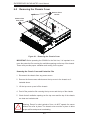
2-4 Installing the System into a Rack
This section provides information on installing the chassis into a rack unit with the
rails provided. There are a variety of rack units on the market, which may mean
that the assembly procedure will differ slightly from the instructions provided. You
should also refer to the installation instructions that came with the rack unit you are
using. Note: This rail will fi t a rack between 26.5" and 36.4" deep.
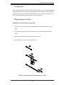
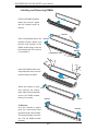
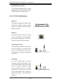
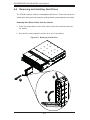
Identifying the Sections of the Rack Rails
The chassis package includes two rail assemblies in the rack mounting kit. Each
assembly consists of three sections: An inner chassis rail that secures directly to
the chassis, an outer rail that secures to the rack, and a middle rail, which extends
from the outer rail. These assemblies are specifi cally designed for the left and right
side of the chassis.
Figure 2-1. Identifying the Outer, Middle and Inner Rails
(Left Rail Assembly Shown)
Inner Rail
Rail Assembly
(Shown with Rails
Retracted)
This Side Faces
Outward
Locking Tab
Middle Rail
Outer Rail

Chapter 2: Server Installation
2-5
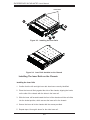
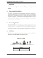
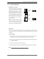
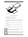
Figure 2-2. Extending and Releasing the Inner Rail
1
2
1
1
1
3
1
4
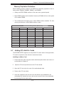
Locking Tabs
Each inner rail has a locking tab. This tab locks the chassis into place when installed
and pushed fully into the rack. These tabs also lock the chassis in place when fully
extended from the rack. This prevents the server from coming completely out of
the rack when when the chassis is pulled out for servicing.
Releasing the Inner Rail
Releasing Inner Rail from the Outer Rails
1. Identify the left and right outer rail assemblies as described on the previous
page.
2. Pull the inner rail out of the outer rail until it is fully extended as illustrated
below.
3. Press the locking tab down to release the inner rail.
4. Repeat steps 1-3 for the remaining outer rail.

2-6
SUPERSERVER 5037MR-H8TRF User's Manual
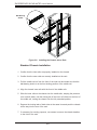
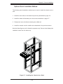
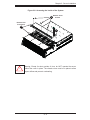
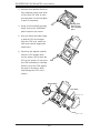
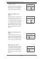
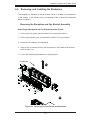
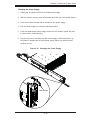
Figure 2-3. Installing the Inner Rails
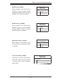
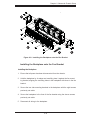
Figure 2-4. Inner Rails Installed on the Chassis
Installing The Inner Rails on the Chassis
Installing the Inner Rails
1. Confi rm that the left and right inner rails have been correctly identifi ed.
2. Place the inner rail fi rmly against the side of the chassis, aligning the hooks
on the side of the chassis with the holes in the inner rail.
3. Slide the inner rail forward toward the front of the chassis until the rail clicks
into the locked position, which secures the inner rail to the chassis.
4. Secure the inner rail to the chassis with the screws provided.
5. Repeat steps 1 through 4 above for the other inner rail.
1
3
1
4
1
4
1
2
Inner Rails
Page is loading ...
Page is loading ...
Page is loading ...
Page is loading ...
Page is loading ...
Page is loading ...
Page is loading ...
Page is loading ...
Page is loading ...
Page is loading ...
Page is loading ...
Page is loading ...
Page is loading ...
Page is loading ...
Page is loading ...
Page is loading ...
Page is loading ...
Page is loading ...
Page is loading ...
Page is loading ...
Page is loading ...
Page is loading ...
Page is loading ...
Page is loading ...
Page is loading ...
Page is loading ...
Page is loading ...
Page is loading ...
Page is loading ...
Page is loading ...
Page is loading ...
Page is loading ...
Page is loading ...
Page is loading ...
Page is loading ...
Page is loading ...
Page is loading ...
Page is loading ...
Page is loading ...
Page is loading ...
Page is loading ...
Page is loading ...
Page is loading ...
Page is loading ...
Page is loading ...
Page is loading ...
Page is loading ...
Page is loading ...
Page is loading ...
Page is loading ...
Page is loading ...
Page is loading ...
Page is loading ...
Page is loading ...
Page is loading ...
Page is loading ...
Page is loading ...
Page is loading ...
Page is loading ...
Page is loading ...
Page is loading ...
Page is loading ...
Page is loading ...
Page is loading ...
Page is loading ...
Page is loading ...
Page is loading ...
Page is loading ...
Page is loading ...
Page is loading ...
Page is loading ...
Page is loading ...
Page is loading ...
Page is loading ...
Page is loading ...
Page is loading ...
Page is loading ...
Page is loading ...
Page is loading ...
Page is loading ...
Page is loading ...
Page is loading ...
Page is loading ...
Page is loading ...
Page is loading ...
Page is loading ...
-
 1
1
-
 2
2
-
 3
3
-
 4
4
-
 5
5
-
 6
6
-
 7
7
-
 8
8
-
 9
9
-
 10
10
-
 11
11
-
 12
12
-
 13
13
-
 14
14
-
 15
15
-
 16
16
-
 17
17
-
 18
18
-
 19
19
-
 20
20
-
 21
21
-
 22
22
-
 23
23
-
 24
24
-
 25
25
-
 26
26
-
 27
27
-
 28
28
-
 29
29
-
 30
30
-
 31
31
-
 32
32
-
 33
33
-
 34
34
-
 35
35
-
 36
36
-
 37
37
-
 38
38
-
 39
39
-
 40
40
-
 41
41
-
 42
42
-
 43
43
-
 44
44
-
 45
45
-
 46
46
-
 47
47
-
 48
48
-
 49
49
-
 50
50
-
 51
51
-
 52
52
-
 53
53
-
 54
54
-
 55
55
-
 56
56
-
 57
57
-
 58
58
-
 59
59
-
 60
60
-
 61
61
-
 62
62
-
 63
63
-
 64
64
-
 65
65
-
 66
66
-
 67
67
-
 68
68
-
 69
69
-
 70
70
-
 71
71
-
 72
72
-
 73
73
-
 74
74
-
 75
75
-
 76
76
-
 77
77
-
 78
78
-
 79
79
-
 80
80
-
 81
81
-
 82
82
-
 83
83
-
 84
84
-
 85
85
-
 86
86
-
 87
87
-
 88
88
-
 89
89
-
 90
90
-
 91
91
-
 92
92
-
 93
93
-
 94
94
-
 95
95
-
 96
96
-
 97
97
-
 98
98
-
 99
99
-
 100
100
-
 101
101
-
 102
102
-
 103
103
-
 104
104
-
 105
105
-
 106
106


Supermicro Super Microcloud 5037MR-H8TRF User manual
- Category
- Server barebones
- Type
- User manual
- This manual is also suitable for
Ask a question and I''ll find the answer in the document
Finding information in a document is now easier with AI
Related papers
-
Supermicro SuperServer 5038MR-H8TRF User manual
-
-
-
-
-
-
-
-
-
Other documents
-
Emprex COL-3101 Installation guide
-
 Ci Design SR 208 Installation guide
-
 Supero SUPERSERVER 2027TR-D70RF+ User manual
-
SUPER MICRO Computer 1018D-73MTF User manual
-
Intel SR9000MK4U User manual
-
Gigabyte W291-Z00 Installation Instructions Manual
-
Gigabyte 25HB2-A66122-K0R Installation guide
-
Lenovo THINKSERVER RD230 Rack Installation Instructions
-
Gigabyte W771-Z00 Owner's manual
-

