NTI FTVN110 User manual

Type
User manual

NTI FTVN110 is a versatile gas boiler designed for efficient heating and domestic hot water production. Its advanced technology and durable construction make it an ideal choice for residential and commercial applications. With a compact design, the FTVN110 easily fits into tight spaces while delivering reliable performance. It features a user-friendly control panel with a digital display, allowing for precise temperature adjustments and monitoring of various operating parameters. The FTVN110 operates quietly, ensuring a peaceful indoor environment.

NTI FTVN110 is a versatile gas boiler designed for efficient heating and domestic hot water production. Its advanced technology and durable construction make it an ideal choice for residential and commercial applications. With a compact design, the FTVN110 easily fits into tight spaces while delivering reliable performance. It features a user-friendly control panel with a digital display, allowing for precise temperature adjustments and monitoring of various operating parameters. The FTVN110 operates quietly, ensuring a peaceful indoor environment.

Applicable Models:
FTVN085, FTVN110, FTVN150, FTVN199,
FTVN110C, FTVN150C, and FTVN199C
FTVNFTVN
NATURAL TO PROPANE NATURAL TO PROPANE
CONVERSION INSTRUCTIONSCONVERSION INSTRUCTIONS
This conversion kit shall be installed by a qualified
service agency in accordance with the manufacturers
instructions and all applicable codes and requirements
of the authority having jurisdiction. If the information
in these instructions is not followed exactly, a fire, an
explosion or production of carbon monoxide may result
causing property damage, personal injury or loss of
life. The qualified service agency is responsible for the
proper installation of this kit. THE INSTALLATION IS NOT
PROPER AND COMPLETE UNTIL THE OPERATION OF THE
CONVERTED APPLIANCE IS CHECKED AS SPECIFIED IN
THE MANUFACTURER’S INSTRUCTIONS SUPPLIED WITH
THE KIT, WHICH NECESSITATES THE USE OF A CALIBRATED
CO2/O2 AND CO COMBUSTION ANALYZER.
WARNING
2
Part 0. General Safety information
NTI boilers are factory set to operate
with Natural Gas.
BEFORE OPERATING WITH PROPANE
the boiler must be converted to
Propane using this kit.
Use the procedures outlined in these
instructions to fully complete the
Natural Gas to LP conversion for
models 085, 110, 150, 199, 110C,
150C and 199C.
Kit Contents:
- Natural to LP Conversion Instructions nr. 1
- LP Conversion Label nr. 1
- LP-Mixer w. Diaphragm (Table 1) nr. 1
- Gasket for gas pipe nr. 2
Model Polidoro code
(MIXER data plate)
LP diaphragm
Ø in (mm)
085, 110, and 110C
350_0944_02
or
350_0944_03 6.4 mm
150 and 150C
350_0921_02
or
350_0921_03
199 and 199C
350_0922_02
or
350_0922_03
6.9 mm
Table 1 - LP Mixer and Gas diaphragm
Data plate
LP diaphragm
IF THE KIT CONTENTS DO NOT MATCH
THOSE SPECIFIED FOR YOUR BOILER
MODEL (SEE TABLE 1), DO NOT
PROCEED WITH INSTALLING THE
LP-CONVERSION KIT, AND DO NOT
OPERATE THE BOILER - CONTACT NTI
FOR ASSISTANCE.
3
Part 0. General Safety information
These instructions CANNOT be
used to convert NTI appliance
models not referenced in these
instructions. Contact NTI for the
Natural Gas to LP conversion kit
and instructions for other models.
Failure to apply these instructions
properly may result in dangerous
Carbon Monoxide levels, fire or
explosion leading to property
damage, personal injury or death.
ATTENTION:
LIQUEFIED PETROLEUM (LP)
PROPANE
Liquefied Petroleum (LP)
propane gas is heavier than air;
therefore, it is imperative that
your boiler is not installed in a
pit or similar location that will
permit heavier than air gas to
collect.
Local Codes may require
appliances fueled with LP gas
be provided with an approved
means of removing unburned
gases from the room. Check
your local codes for this
requirement.
WARNING
4
Part 1 Propane Conversion Procedure
1.
Install LP-Mixer with
LP-Diaphragm
a. Check that the code of the air / gas mixer
and the diameter of the gas diaphragm
are those indicated for the model of boiler
to be converted – see Table 1.
b. Turn the 120VAC power supply OFF to the
boiler.
c. Turn the gas supply OFF.
d. Remove the front cover from the unit.
e. Remove the silencer.
f. Unscrew the two nuts and remove the
gas pipe.
g. Remove the three bolts securing the
NG-mixer to the blower and remove the
NG-Mixer.
NOTICE: 150/150C NG-MIXERS ARE
EQUIPPED WITH AN NG DIAPHRAGM
LOCATED ON THE MIXER GAS LINE INLET
(SEE FIGURE 4 FOR GENERAL DIAPHRAGM
LOCATION).
NOTICE: SAVE THE NG-MIXER (AND NG
DIAPHRAGM FOR 150/150C) IN-CASE THE
BOILER NEEDS TO BE CONVERTED BACK
TO NATURAL GAS AT A LATER DATE.
h. Secure the LP-Mixer (with LP Diaphragm)
to the blower in the same position as the
removed NG-Mixer, reusing the bolts from
the previous step.
NOTICE: VERIFY THE O-RING SEAL
BETWEEN THE MIXER AND BLOWER IS
CORRECTLY POSITIONED AND IN GOOD
CONDITION BEFORE ASSEMBLING.
Figure 2 - Remove the gas pipe
Figure 4 - Insert the LP-diaphragm
Figure 3 - Remove the NG-mixer
LP - Gas diaphragm
Figure 1 - Remove the Silencer
5
Part 1 Propane Conversion Procedure
2. Perform preliminary adjustment on
gas valve throttle screw 4.
a. 085, 110, and 110C: Adjust throttle
screw 4 - counter-clockwise 0.5 turns.
b. 150, 199, 150C, and 199C: Adjust
throttle screw 4 - counter-clockwise 2
turns.
c. Turn the gas supply on and test for gas
leaks in all piping.
d. Perform gas line pressure test and
combustion calibration in accordance
with Parts 2 and 3.
NOTICE: 199 and 199C Models ONLY:
ADJUST HIGH AND LOW FAN SPEEDS
WHEN CONVERTED TO LP, THE 199 AND
199C MODELS MUST HAVE THE HIGH
AND LOW FAN SPEEDS ADJUSTED FROM
THE NATURAL GAS DEFAULT VALUES.
ACCESS THE TECHNICAL MENU AND
ADJUST PARAMETERS 232, 233, AND
234 IN ACCORDANCE WITH TABLE 4 -
MINIMUM AND MAXIMUM GAS FLOW,
IN THIS DOCUMENT.
i. Reassemble the gas pipe to the gas
valve and mixer.
ATTENTION!! USE THE NEW
RUBBER GASKETS PROVIDED
WITH THE KIT.
j. Install the silencer.
4
2
1
Figure 5 - Gas valve
6
Part 2. Gas valve and burner setup
2. Gas Line pressure
The boiler gas valve is equipped with a Line
Pressure Test Port; see screw 1, Figure 5.
Use the following procedure to measure the
gas line pressure to the boiler to ensure it falls
within the range given in Table 2:
a. Turn the supply of gas to the boiler off.
b. Loosen screw 1 (Torx 10 - Line Pressure
Test Port). This port is directly connected
to the gas line feeding the boiler. See
screw 1, Figure 5.
c. Connect a gas pressure gauge to the line
pressure test port using applicable tubing.
Ensure both ends of the tubing make a
tight connection.
d. Turn the gas supply to the boiler on and
check for gas leaks.
e. Observe the line pressure under static
conditions and compare it to Table 2.
The pressure will be greatest under static
conditions.
f. Observe the line pressure with the boiler
running, while checking/adjusting the
CO2 at maximum and minimum gas flow
rate (see Part. 3).
Compare it to Table 2. The pressure will be
lowest during the maximum flow of gas.
1. Operating Sequence
Prior to commencing the Gas Valve and
Burner Setup, perform the following
operating sequence check:
a. Turn the supply of gas to the boiler off.
b. Set the thermostat to the highest setting.
c. Ensure the combustion fan prepurges for
a short time prior to activating the igniter.
d. Ensure the combustion fan postpurges for
at least 5 seconds prior to reactivating the
igniter.
e. Set the thermostat to the lowest setting
and continue with the Gas Valve and
Burner Setup procedure outlined below.
Failure to perform the Gas Valve
and Burner Setup correctly may
result in incorrect operation,
component failure, property
damage, serious injury or death.
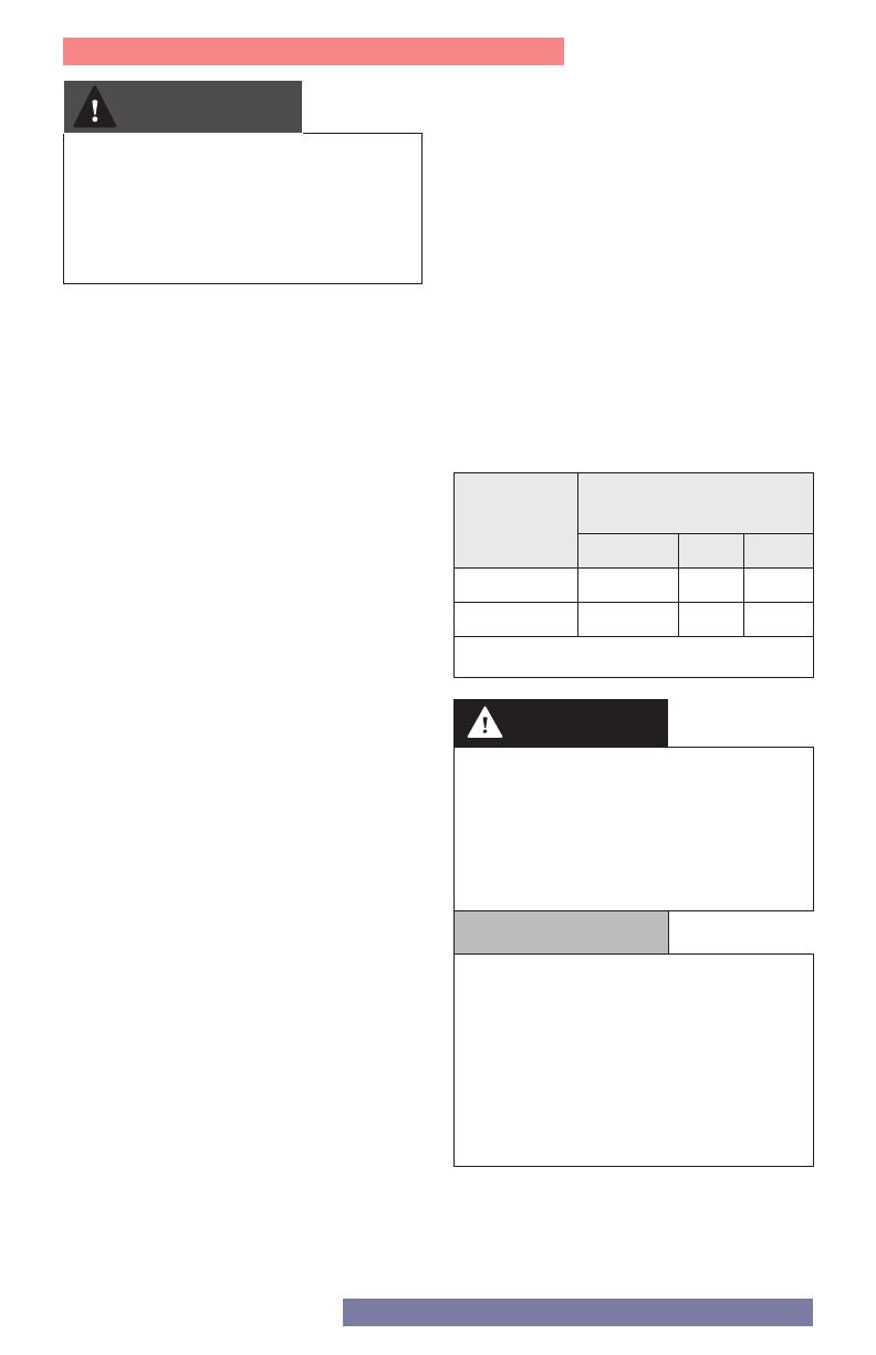
Table 2 - Line Pressure Parameters
Line Pressure
(inches w.c.)
Nominal Min. Max.
Natural 7 3.5 10.5
Propane 11 8 13
Failure to close the bleed screw
of the Line Pressure Test Port will
cause a severe leakage of gas,
resulting in a fire or explosion
causing property damage, serious
injury or death.
g. Adjust the gas line pressure to ensure the
parameters in Table 2 are attained under
all conditions.
If possible, adjust the line pressure to
the “Nominal/Desired” value listed in
Table 2 while the unit is operating at the
maximum power.
Continue observing gas line pressure
until completing of necessary Checking/
Adjusting of the CO2 (see Part 3), in case
adjustments need to be made.
h. Complete pressure testing. Remove the
tubing from the test port and then return
the bleed screw of the Line Pressure Test
Port to the closed position.
Check for gas leaks.
WARNING
DANGER
The line pressure is a function
of the gas supply and is affected
solely by field provided parameters
such as line size and regulator
settings. Under no circumstances
can the boiler gas valve influence
or be used to adjust the gas line
pressure.
NOTICE
7
Part 3. Checking/Adjusting the CO2
It is very important that the
combustion system be set within
the recommended CO2/ CO
measurements listed in Table 3.
Visually looking at the burner does
not determine combustion quality.
Failure to measure combustion
with a calibrated combustion
analyzer and set the throttle within
the recommended CO2/CO
measurements could result in
property damage, severe personal
injury, or death.
1. Preparing the measuring equipment
Remove the flue test port plug as
illustrated, and insert a calibrated
combustion analyzer.
Make sure the analyzer is set to the
appropriate fuel.
It is required to use a calibrated
combustion analyzer to verify final
adjustment according to the combustion
chart (Table 3).
Failure to do so could result in serious
personal injury or death.
Figure 6 - Combustion Test Port
Adjustments to the Gas valve may
only be made by a qualified gas
technician, while using a calibrated
combustion analyzer capable of
measuring CO2 and CO. Adjustments
may only be performed if the gas
line pressure is maintained above
minimum levels throughout the
duration of the test. See Table 3.
Failure to follow these instructions
may result in serious injury or death.
FAILURE TO PERFORM THE FLUE
GAS ANALYSIS AND ADJUSTMENT
AS DETAILED IN THIS SECTION
MAY RESULT IN ERRATIC AND
UNRELIABLE BURNER OPERATION,
LEADING TO REDUCED EFFICIENCY,
INCREASED FUEL CONSUMPTION,
REDUCED COMPONENT LIFE,
HEAT EXCHANGER COMBUSTION
DEPOSITS, AND GENERAL UNSAFE
OPERATION. FAILURE TO FOLLOW
THESE INSTRUCTIONS MAY RESULT
IN SERIOUS INJURY OR DEATH.
WARNING
WARNING
WARNING
WARNING
NOTICE
8
Part 3. Checking/Adjusting the CO2
2.
Checking/Adjusting the CO2 at
Maximum Gas Flow Rate
(High Fan Speed)
Set the thermostat at the highest
possible setting or draw off the domestic
hot water at the maximum water flow
rate to create a demand for heat.
NOTE: For only Heating Boiler
Applications, open all thermostatic
valves present in the CH circuit.
Select the TEST Function by pressing and
holding the RESET button for 10 seconds.
WARNING! WHEN THE TEST FUNCTION IS
ACTIVATED THE TEMPERATURE OF THE
WATER COMING OUT OF THE BOILER MAY
BE MORE THAN 150°F.
and the icon will appear on the
display when Test Function is active.
The boiler will operate at maximum heating
power.
Press the button
to operate the boiler at
maximum power.
The icon will display.
ATTENTION: The CO2 at minimum gas flow
must not be set higher than the CO2
reading a maximum gas flow; it may be
set lower by as much as 1.0%, e.g., if CO2
at Max. = 9.5%, then CO2 at Min. must =
8.5-9.5%.
ATTENTION!! VALUES MUST BE
OBTAINED WITH THE FRONT COVER
INSTALLED.
If the CO2 reading differs from the values
given in the table, then adjust the gas
valve following the instructions below.
Otherwise move directly to next operation.
ADJUSTING THE GAS VALVE AT MAXIMUM
GAS FLOW
Adjust the gas valve by turning setting
screw 4 clockwise to increase the CO2
level; counterclockwise to reduce the
CO2 level (1 turn adjusts the CO2 level by
approximately 0.3%). Wait 1 minute after
each change in setting for the CO2 value
to stabilize.
If the value measured corresponds to the
value given in Table 3, max adjustment is
complete.
Otherwise continue the setting
procedure.
ATTENTION!!
Test Function will automatically
deactivate after 30 minutes.
Test Function can be turned off manually
by pressing the RESET button.
4
Figure 7 - Max CO2 Adjustment
Wait 1 minute for the boiler to stabilize before
carrying out the combustion analyses.
Gas CO2
(%)
CO MAX
(ppm)
Natural
8.5 to 10
175
Propane 9.5 to 11 175
Table 3 -
CO2 max-min
Read the CO2 value (%) and compare it with
the values given in the table below:
9
Part 3. Checking/Adjusting the CO2
3. Checking/Adjusting the CO2 at
Minimum Gas Flow
(Low Fan Speed)
With Test Function active, press the
button to operate the boiler at minimum
DHW power. The and icons will
display.
Wait 1 minute for the boiler to stabilize
before carrying out the combustion
analyses.
ADJUSTING THE GAS VALVE AT
MINIMUM GAS FLOW
Remove cap and adjust screw 2 by
turning counter - clockwise to reduce
the CO2 level; clockwise to increase the
CO2 level.
Wait 1 minute after each adjustment for
the CO2 value to stabilize.
WARNING! MINIMUM GAS FLOW
ADJUSTMENT IS VERY SENSITIVE.
If the value measured corresponds to
the value given in Table 3 adjustment
is complete. Otherwise continue the
setting procedure.
ATTENTION!! IF THE VALUE OF THE
CO2 AT MINIMUM POWER HAS
BEEN CHANGED, IT IS NECESSARY
TO REPEAT THE ADJUSTING AT
MAXIMUM GAS FLOW.
2
Figure 8 - Min CO2 Adjustment
If the CO2 (%) reading at min gas flow is
greater than the CO2 (%) reading at max
flow, or if it is less than the reading at max
flow by more than 1.0%, adjust the gas
valve following the instructions below.
Otherwise move directly to next operation.
Table 4 Minimum and Maximum Gas Flow
Model
Minimum Gas Flow Maximum Gas Flow
P.233 (%) RPM MBH P.234 / P.234 (%) RPM MBH
085 7 1504 8.5 78 6616 85
110 / 110C 11 1792 11.0 100 8200 110
150 / 150C 6 1432 15.0 91 7552 150
199 / 199C NG 4 1288 19.9 91 7552 199
LP 6 1432 93 7696
1. Canada: Altitudes between 2000-4500 ft, de-rate by 10%. Consult local authorities for
de-rating for altitudes above 4500ft.
2.
USA: De-rate capacity by 4% for every 1000 ft above sea level, if altitude is above 2000 ft.
10
Part 3.
Checking/Adjusting the CO2
Carbon Monoxide - Never
leave the unit operating while
producing Carbon Monoxide (CO)
concentrations in excess of the
values indicated in Table 3. Failure
to follow this warning may result in
serious injury or death.
4. Ending Adjustment
1. Exit Test Mode by pressing RESET.
2. Turn down the thermostat and / or stop
the DHW draw-off. For Only Heating
Boiler applications reset all thermostatic
valves.
3. Reinstall the combustion test port.
See Figure 6.
4. Check for and repair any leaks of gas.
5. Reinstall the front cover.
WARNING
11
Part 3.
Checking/Adjusting the CO2
5. Update rating plate
As the certified installer of the Natural Gas
to LP Conversion Kit, you must indicate on
the boiler that it has been converted for
use with Propane (LP) Gas:
a. Update Rating Plate Decal – Locate
the rating plate decal on the side of
the appliance. Using a regular ink pen,
check the box next to “Field converted
to Propane Gas” and fill in the date.
Press hard enough to permanently mark
the decal. See Figure 9.
FACTORY SET FOR NATURAL GAS
Field converted to Propane Gas
ADJUSTER A L’USINE POUR GAZ NATURAL
Convertie au propane sur place
Date: Date:
Gas Pressure [Pression du Gaz ]
Maximum Inlet Gas Pressure [Pression maximale d’entrée du gaz]
Minimum Inlet Gas Pressure [Pression minimum d’entrée du gaz]
Manifold Pressure [Pression d’admission]
Natural [Naturel] Propane
10.5" wc [2.6 kPa]
3,5" wc [1 kPa]
0" wc [0 kPa] 0" wc [0 kPa]
8" wc [2 kPa]
13" wc [3.2 kPa]
October 22,2018
b. Conversion Decal - Fill out the required
information on the Conversion Decal
(included in this kit) and affix it to the
boiler cabinet adjacent to the rating
plate decal, in a location where it can be
easily seen. See Figure 10.
Figure 9 - Update the Rating Plate Decal
Figure 10 - Conversion Decal
THIS CONTROL WAS CONVERTED FOR USE WITH PROPANE GAS
This appliance has been converted for use with Propane Gas, in accordance with the
instructions provided with the Natural to Propane Conversion Kit
by ______________________________________ , which accepts responsibility that
the conversion was performed properly.
Reference rating plate for Propane Input and Gas Pressure
420060882600
John Smith
NTI Boilers Inc.
30 Stonegate Drive Saint John,
NB E2H 0A4 Canada
Technical Assistance: 1-800-688-2575
Website: www.ntiboilers.com
Fax: 1-506-432-1135
Visit us online
420020241500
  • Page 1 1
  • Page 2 2
  • Page 3 3
  • Page 4 4
  • Page 5 5
  • Page 6 6
  • Page 7 7
  • Page 8 8
  • Page 9 9
  • Page 10 10
  • Page 11 11
  • Page 12 12

NTI FTVN110 User manual

Type
User manual

NTI FTVN110 is a versatile gas boiler designed for efficient heating and domestic hot water production. Its advanced technology and durable construction make it an ideal choice for residential and commercial applications. With a compact design, the FTVN110 easily fits into tight spaces while delivering reliable performance. It features a user-friendly control panel with a digital display, allowing for precise temperature adjustments and monitoring of various operating parameters. The FTVN110 operates quietly, ensuring a peaceful indoor environment.

Ask a question and I''ll find the answer in the document

Finding information in a document is now easier with AI