Page is loading ...

1.0 SPECIFICATIONS..................................................................................................2
1.1 HIGH ALTITUDE OPERATION..................................................................................2
2.0 INSTALLATION REQUIREMENTS ...................................................................2
3.0 VENTING .................................................................................................................4
3.1 VENT PIPE MATERIAL ............................................................................................4
3.3 VENTING RULES AND GUIDELINES.........................................................................7
3.4 VENTING CLEARANCES ..........................................................................................7
4.0 CONDENSATE DRAIN..........................................................................................9
5.0 INSTALLING GAS PIPING...................................................................................9
5.0 INSTALLING GAS PIPING.................................................................................10
5.1 INSTALLATION......................................................................................................10
5.2 TESTING AND SETTINGS ........................................................................................10
6.0 HEATING SYSTEM PIPING...............................................................................12
6.1 PRIMARY LOOP PLUMBING...................................................................................13
6.2 SECONDARY LOOP HEATING SYSTEM ..................................................................16
6.2.1 Multiple Zones using Zone Valves.............................................................16
6.2.2 Multiple Zones using Pumps......................................................................16
6.2.3 Multiple Zones with Different Temperatures............................................17
6.3 DOMESTIC COMBI SYSTEM...................................................................................18
7.0 WIRING..................................................................................................................20
7.1 SIMPLIFIED WIRING CONNECTIONS......................................................................21
7.2 ADVANCED WIRING SYSTEMS..............................................................................22
7.2.1 Multiple 4 wire Zone Valves.......................................................................22
7.2.2 Multiple Zones with Taco Valve controller................................................23
7.2.3 Multiple Zones Pump controller................................................................24
7.2.4 Multiple Temperature Zones with Injection Pumps..................................25
8.0 SENTRY 2100 CONTROLLER ...........................................................................26
9.0 LIGHTING BOILER.............................................................................................30
9.1 INITIAL START-UP.................................................................................................30
9.2 RE-LIGHTING UNIT...............................................................................................30
9.3 TURN OFF BOILER.................................................................................................30
10.0 TROUBLE SHOOTING......................................................................................31
11.0 SEQUENCE OF OPERATION..........................................................................34
14.0 ANNUAL MAINTENANCE AND INSPECTION............................................36
14.1 COMBUSTION CHAMBER CLEANING...................................................................36
15.0 PARTS LIST.........................................................................................................37
CAUTION:
IT IS THE RESPONSIBILITY OF THE HOMEOWNER TO
KEEP THE VENT TERMINAL CLEAR OF SNOW AND ICE.
Trinity Ti Boiler Only
VERSION DATE: 1-5-2010
Installation and
Operation Instructions
Trinit
y
Ti
This Boiler must be installed by a licensed and trained Heating
Technician; otherwise the warranty of this unit is void. Failure
to properly install this unit could cause damage to property
and injury to occupants possibly resulting in death.

2
ATTENTION: LIQUEFIED PETROLEUM (LP) PROPANE
The Trinity boiler is set to operate with Natural Gas; LP Conversion Kit Part No. 82650-1 for Ti100’s, Ti150’s and
Ti200’s, or LP Conversion Kit Part No. 83017-1 for Ti400’s is included with each boiler and must be installed before
operating with Propane.
Liquefied Petroleum (LP) propane gas is heavier than air; it is imperative that your boiler is not installed in a pit or
similar location that will permit heavier than air gas to collect. Local Codes may require appliances fueled with LP gas
be provided with an approved means, of removing unburned gases from the room. Check your local codes for this
requirement.
Warning
THIS BOILER MUST HAVE WATER
FLOWING THROUGH IT WHENEVER
THE BURNER IS ON. FAILURE TO DO
THIS WILL DAMAGE THE UNIT AND
VOID THE WARRANTY.
0
100
200
300
400
0-
2000
3000 4000 5000 6000 7000 8000 9000 10000
Elevation (ft)
Input (Mbh)
Ti150 Ti200 Ti400 Ti100
1.0 SPECIFICATIONS
Description Ti 100 Ti 150 Ti 200 Ti 400
Input (BTUx1000)
Input Capacity - Max. / Min.
Natural =100 / 15
Propane= 100 / 15
Natural =150 / 25
Propane= 145 / 25
Natural = 200 / 25
Propane= 194 / 25
Natural = 399 / 75
Propane= 399 / 75
Output (BTUx1000)
Output Capacity - Max./ Min.
Natural =92.7 / 13.9
Propane = 92.7/ 13.9
Natural =139 / 23.2
Propane = 134 / 23.2
Natural = 185 / 23.2
Propane = 180 / 23.2
Natural = 370 / 69.5
Propane = 370 / 69.5
Steady State Efficiency 95% 95% 94% 94%
AFUE Efficiency 95.1%
Venting material CPVC, PVC (See Section 3.1)
Max. Vent lengths Natural Gas
3” @ 105’ Equivalent
Max. Vent lengths Propane
3” @ 105’ Equivalent
3” @ 50’ Equivalent
4” @ 30’ Equivalent
6” @ 65’ Equivalent
Weight
80 lbs. 80 lbs.
110 lbs.
205 lbs.
Dimensions L-W-D (Inches)
22.5x15.25x14 22.5x15.25x14
22.5x15.25x17.25
23.5x21x36
Clearance to Combustibles
0”
1.1 High Altitude Operation
The Trinity boiler is designed to operate to capacity in
installations with 2000 feet of elevation or less. As
elevations higher than 2000 feet have less dense air, the unit
is not capable of providing its specified capacity. (See
Chart).
In Canada:
De-rate by 5% for altitudes between 2000 and 4500 feet.
For altitudes above 4500 feet consult with local authorities.
In USA:
De-rate by 4% for every 1000 feet over 2000 feet.
CAUTION At elevations greater than 2000 feet, the
combustion of the Trinity must be checked with a calibrated
combustion tester to ensure safe and reliable operation.
Consult Section 5.20 for instructions on adjusting the input to
provide proper operation. It is the Installers responsibility to
check the combustion, and to adjust the combustion in
accordance to Section 5.2
2.0 INSTALLATION REQUIREMENTS
Important: Carbon Monoxide Detectors
The installation of your NY Thermal Trinity gas boiler must
conform to the requirements of your local authority, and the National Fuel Gas Code ANSI Z223.1 and or CAN/CGA B149 Installation
Codes. Where required by the Authority, the installation must conform to the standard for “Controls and Safety Devices for Automatically
Fired Boilers ANSI/ASME CSD-1.

3
“In the State of Massachusetts only”
(a)For all horizontally vented gas fueled equipment installed in every dwelling, building or structure used in whole or in part for
residential purposes, including those owned and operated by the Commonwealth and where the side wall exhaust vent termination is
less than seven (7) feet above finished grade in the area of the venting, including but not limited to decks and porches, the following
requirements shall be satisfied:
1. INSTALLATION OF CARBON MONOXIDE DETECTORS. At the time of installation of the side wall horizontal vented
gas fueled equipment, the installing plumber or gas fitter shall observe that a hard wired carbon monoxide detector
with an alarm and battery back-up is installed on the floor level where the gas equipment is to be installed and on each
additional level of the dwelling, building or structure served by the equipment. It shall be the responsibility of the property
owner to secure the services of qualified licensed professionals for the installation of hard wired carbon monoxide detectors.
a. In the event that the side wall horizontally vented gas fueled equipment is installed in a crawl space or an attic, the
hard wired carbon monoxide detector with alarm and battery back-up may be installed on the next adjacent floor
level.
b. In the event that the requirements of this subdivision can not be met at the time of completion of installation, the
owner shall have a period of 30 days to comply with the above requirements; provided, however, that during said
30 day period a battery operated carbon monoxide detector with an alarm shall be installed.
2. APPROVED CARBON MONOXIDE DETECTORS. Each carbon monoxide detector as required in accordance with the
above provisions shall comply with NFPA 720 and be ANSI/UL 2034 listed and IAS certified.
3. SIGNAGE. A metal or plastic identification plate shall be permanently mounted to the exterior of the building at a
minimum height of eight (8) feet above grade directly in line with the exhaust vent terminal for the horizontally vented gas
fueled heating appliance or equipment. The sign shall read, in print size no less than one-half (1/2) inch in size, “GAS
VENT DIRECTLY BELOW. KEEP CLEAR OF ALL OBSTRUCTIONS”. (Plate include with boiler)
4. INSPECTION. The state or local gas inspector of the side wall horizontally vented gas fueled equipment shall not approve
the installation unless, upon inspection, the inspector observes carbon monoxide detectors and signage installed in
accordance with the provisions of 248 CMR 5.08(2)(a)1 through 4.
(b)EXEMPTIONS: The following equipment is exempt from 248 CMR 5.08(2)(a)1 through 4:
1. The equipment listed in Chapter 10 entitled “Equipment Not Required To Be Vented” in the most current edition of NFPA
54 as adopted by the Board; and
2. Product Approved side wall horizontally vented gas fueled equipment installed in a room or structure separate from the
dwelling, building or structure used in whole or in part for residential purposes.
(c)MANUFACTURER REQUIREMENTS – GAS EQUIPMENT VENTING SYSTEM PROVIDED. When the manufacturer of
Product Approved side wall horizontally vented gas equipment provides a venting system design or venting system components with
the equipment, the instructions provided by the manufacturer for installation of the equipment and the venting system shall include:
1. Detailed instructions for the installation of the venting system design or the venting system components; and
2. A complete parts list for the venting system design or venting system.
(d)MANUFACTURER REQUIREMENTS – GAS EQUIPMENT VENTING SYSTEM NOT PROVIDED. When the manufacturer
of a Product Approved side wall horizontally vented gas fueled equipment does not provide the parts for venting the flue gases, but
identifies “special venting systems”, the following requirements shall be satisfied by the manufacturer:
1. The referenced “special venting system” instructions shall be included with the appliance or equipment installation
instructions; and
2. The “special venting systems” shall be Product Approved by the Board, and the instructions for that system shall include a
parts list and detailed installation instructions.
(e)A copy of all installation instructions for all Product Approved side wall horizontally vented gas fueled equipment, all venting
instructions, all parts lists for venting instructions, and/or all venting design instructions shall remain with the appliance or
equipment at the completion of the installation.

4
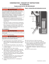
Ti100-200:
-3” male PVC
Exhaust Fitting.
3” Coupling
Field Provided
2.1 Location
In all cases, the Trinity boiler must be installed indoors, in a dry location, such that the gas components are protected from dripping or
spraying water or rain, during operation and servicing. The boiler location ambient temperature is maintained to a minimum of 50°F.
Determine the best location of the vent termination, and if possible locate the boiler as close to the termination point as possible.
3.0 VENTING
The NY Thermal Trinity condensing gas boiler is a high efficiency boiler utilizing induced power venting. Exhaust gases are to be vented
directly outdoors, using the venting methods detailed in this section. Under no conditions may this unit vent gases into a masonry
chimney, unless it is vacant, and utilizes the Trinity approved venting material as illustrated in this section. Installation must comply with
local requirements and with the National Fuel Gas Code, ANSI Z223.1 for U.S. installations or CSA B149.1 for Canadian Installations.
Attaching Vent Piping to Boiler
• It is extremely important for the intake and exhaust piping to be
adapted to the appropriate size immediately upon exiting the boiler cabinet. Ti100-200’s come with a 3”x1-1/2” PVC adapter to
be used to immediately connect to the air intake port of the boiler.
• Ti100-200 exhaust connection is 3” male PVC, use approved cement to connect to venting system.
• Ti400 exhaust connection accepts approved 4” venting material, do not insert PVC pipe directly into the exhaust connection;
PVC pipe could become deformed by the clamping force of the gear clamp. Only approved CPVC can be inserted into the Ti400
exhaust connection. Note: a 4” long piece of 4” CPVC is provided with the Ti400.
• Check the flue outlet gasket for proper insertion and sealing prior to and after attaching the venting.
• Ensure the venting system does not apply a load or stain on the flue outlet of the boiler (recommend using two elbows to create a
“swing joint” as shown above).
3.1 Vent Pipe Material
Exhaust Vent Piping:
• The first 3 feet of the exhaust venting must be readily accessible for inspection.
• In Canada all exhaust pipe, fittings and cement must comply with ULC S636 (ULC S636 PVC pipe is approved for flue gas
temperatures up to 149ºF (65ºC), therefore it can only be used in low temperature applications; systems requiring boiler supply
water temperature greater than 140ºF must use ULC S636 approved CPVC).
• In U.S. exhaust pipe and fittings must comply with ANSI/ASTM D1785 and DF441 for PVC and CPVC, respectively. Cement
and primer must comply with ANSI/ASTM D2564 and F493 for PVC and CPVC respectively.
• Ti100-200
• 3” PVC
Sch.40 (See note above for installations in Canada).
• 3” CPVC
Sch.40.
• Ti400
• 4 or 6” PVC
Sch.40 (See note above for installations in Canada).
• 4 or 6” CPVC
Sch.40.
Air Supply Pipe:
• 3” ABS. (Use 4” or 6” for Ti400)
• 3” PVC
Sch.40. (Use 4” or 6” for Ti400)
Clearances
For proper and safe installation adhere to the following clearances to combustibles:
Boiler Casing=0" Floor=Combustible Flue Pipe: Boxed in or enclosed=2” In free air=0”
The following are the minimum clearances for servicing, however 24” is recommended:
Front = 24” Back = 0" Top = 12" Sides = 12" Bottom = 9" (0” for Ti400)
It is recommended that two
elbows be used, so that the slope
of the horizontal exhaust vent
does not affect the vertical plumb
of the pipe connected to the boiler.
Slope all horizontal indoor
exhaust venting ¼” to ½” per
linear foot.

5
3.2 Venting Configurations
3.2.1 Two-Pipe Vent Termination
3.2.2 Concentric Vent Termination (No longer approved for Canada)
• Ti100-200 Only (Not for use with Ti400)
• NTI part number 82666 (York part number 1CT0303)
• Instructions included with vent terminal contain more detailed assembly and installation instructions.
• Clearances and requirements of this manual supersede those of the instructions included with the vent terminal.
• Terminal must be cemented together during installation.
12” Plus Snow allowance
Example 12+19=31”
Coupling and
elbow to be
against wall
– ½” play is
acce
p
table
18” Min
The vertical portion of the exhaust
termination does not require
insulation, if less than 5 feet in total
length
Must insert
plastic bird
sc
r
ee
n
Apply Plate
Gas Vent Directly Below
Kee
p
Free of Obstructions 36”
1
8
”
4”-12” or greater
than 36”
Outside Wall”
Exhaust
Intake
Window
12” Plus Snow
Allowance Min
”
Must insert
plastic bird
screen
Must be 1”
from wall
Support
(Field installed)
Inlet
Exh
aust
Inlet
Exh
aust
Note: inlet pipe must always
be connected to the boiler.
36” min.
Minimum 12”
p
lus snow
allowance
4” or greater
than 24”
48” min.
Gas Vent Directly Below
Keep Free of Obstructions
App
l
y
Plate Here

6
3' Minimum
12" Plus Snow
Allowance
(Minimum)
Window
3.2.3 Ti400 Optional Vent Termination Kit
• NTI part number 83236.
• For use with Ti400 only.
• 4” Connections (When venting with 6”, must adapt down at terminal)
• See Installation Manual included in vent terminal kit for further instructions.
3.2.4 Roof Venting
It is permissible to run vent pipe through an existing chimney as long as:
1) The chimney is not being used by any other appliance.
2) Flue gases don’t enter the vacant chimney.
3) Only Trinity certified venting materials are used, see Section 3.1.
4) Vent lengths are within the maximums specified.
Gas Vent Directly Below
Keep Free of Obstructions
Support
(Field supplied)
Exhaus
t
24
”
Inlet Ai
r
Exhaus
t
Inlet Ai
r
Roof weather seal
Flashing (field supplied)
Note: inlet pipe must
always be connected
to the boiler.
12” Plus
Snow
18”

7
3.3 Venting Rules and Guidelines
1. It is highly recommended that the vent terminal be located where it will not be exposed to normal prevailing winds.
2. Air for combustion must be drawn from outdoors from an area free of dust and contaminants. Combustion air containing chemicals
such as chloride, fluoride, bromine or iodine, will cause corrosion damage of the heat exchanger voiding your NTI warranty. Avoid
drawing combustion air from the vicinity of swimming pools, laundry facilities, workshops, or other areas where the air may contain
chemicals or dust.
3. The exhaust must be a minimum of 18” above the air inlet, and the air inlet must always be a minimum of 12” plus snow allowance
above any surface that will support snow. (Two feet plus snow allowance is highly recommended). Consult your weather office, for
the maximum typical snowfall for your region. Example: New Brunswick Canada the typical maximum snowfall is 19”, Thus in
figures of Section 3.3, the inlet must be (12”+19”) = 31” off the ground, the exhaust must be (31”+18”) = 49”.
4. The horizontal distance between the inlet and exhaust must be a minimum of 4” center to center. If the horizontal distance between
the inlet and exhaust is more then 12”, increase the vertical separation by the same amount. Example: If horizontal separation is 24”,
a minimum vertical separation of 30” is required (24”-12”=12”), so increase minimum vertical separation by 12”), (18”+12”=30”). If
horizontal distance is greater then 6’, no additional vertical spacing is required. Vertical separation is never required to be greater
then 36”.
5. Under normal operating conditions this appliance will produce a plume of white gases, and should be taken into consideration when
selecting an adequate location. A 3’ diameter stainless, plastic, or vinyl shield can be used to flash the exterior of the residence.
6. If the horizontal distance between the inlet and exhaust is more then 12”, increase minimum vertical separation by the same amount.
(If horizontal distance is greater then 6’, no additional vertical spacing is required). Example, horizontal separation equal to 24”
requires a minimum vertical separation of 18”+(24”-12”) =30”. (Vertical separation is never required to be greater then 36”)
7. Elbows on outside of wall must be no greater than ½” away from the wall.
8. All indoor exhaust piping must be on a slope back to the boiler a minimum of ¼” per linear foot of vent. For applications where
excessive condensation is possible ½” per linear foot is recommended.
9. Exhaust vent pipe can be secured to the wall for more rigidity.
10. In all roof applications the discharge must point away from the pitch of the roof.
11. Install adequate flashing where the pipe enters the roof, to prevent water leakage.
12. Install and seal a rain cap over existing chimney openings, in vacant chimney applications.
13. For installations that exit the wall below grade. Excavate site as
shown in figure, to a point below where the pipes are to exit. Ensure
that the wall is fully sealed where the pipes penetrate the wall. The
vent piping MUST be secured to the side of the building above
grade, as shown, to provide rigidity. NTI Provides a mounting
bracket PN. 82075 for securing the exhaust pipes. Ensure that the
vent clearances are maintained (Inlet minimum 12” plus snow
allowance from grade, exhaust outlet 18” minimum above inlet)
14. Install the vent screens provided into both the inlet and exhaust vent
terminal elbows. The screen must be on the outside of the last
elbow. Install the screen into the female opening of the elbow. Then
cut a small piece of pipe to sandwich the screen into the elbow.
NOTE be sure that the small piece of pipe cut, does not extend past
the end of the elbow. Two screens are provided in the package.
15. It is extremely important that the intake and exhaust piping be
adapted to the appropriate size immediately upon exiting the boiler
cabinet.
16. All interior vent pipe shall be supported a minimum of every 36” (6”-
diameter pipe used with the Ti400, need only be supported every
48”).
17. Install the warning plate “Gas Vent Directly Below” 4 feet above the location of the air inlet pipe, so it is visible from at least eight
(8) feet away.
3.4 Venting Clearances
These are code restrictions for the location of the Flue gas vent terminal. Compliance doesn’t insure a satisfactory installation;
good common sense must also be applied.
The vent terminal shall not terminate:
1. Directly above a paved sidewalk or a paved driveway that is located between two buildings, and that serves both buildings;
2. Less than 7 feet above grade where located adjacent to a paved walkway or driveway located on public property.
3. Within 3' (three feet) of a window or door that can be opened, or non-mechanical air supply inlet to any building.
Installing Venting Below Grade

8
4. Within 6’ of a mechanical air supply inlet to any building, or roof eve containing soffit openings.
5. Above a meter/regulator assembly within 3' horizontally of the vertical centerline of the regulator.
6. Within 3' horizontally of any gas service regulator vent outlet up to a height of 15’.
7. Less than 30” plus snow allowance above grade, or any surface that will support snow, ice, or debris. The exhaust must be a
minimum of 18” above the air inlet, and the air inlet must always be a minimum of 12” plus snow allowance above any surface that
will support snow. (Two feet plus snow allowance is highly recommended). Consult your weather office, for the maximum typical
snowfall for your region.
8. Underneath a wooden verandah, porch, or deck.
9. Underneath cement verandah, porch, or deck, unless both ends are open and the exhaust pipe is installed at least 24” under the deck
floor.
10. So situated that the flue gases are directed towards brickwork, siding, or other construction, in such a manner that may cause damage
from heat or condensate from the flue gases.
11. Less than 3’ from an inside corner of an L-shaped structure (including walls and fences).
3.5 Determining Vent Lengths
Use the following chart to determine the maximum amount of vent pipe that can be used. This chart calculates, sweep and 45º elbows, and
90º elbows at 5 equivalent feet. Note: chart shows allowable equivalent vent lengths for intake and exhaust vents separately, thus a Ti100
can be installed with 105 equivalent feet of intake venting and 105 equivalent feet of exhaust venting.
IMPORTANT:
• The length of one vent pipe (intake or exhaust) may not exceed the length of the other vent pipe by more then 20 equivalent feet.
• The three 90° elbows of the exterior vent piping (two outlet, and one inlet) do not have to be included, as they are taken into
consideration in the vent calculations.
• For 150 and 200 Models, Propane Gas (LP) maximum vent length cannot exceed 50 equivalent feet.
3.6 Outdoor Horizontal Venting
Vent piping outside the Building is permitted under the following conditions:
1. The maximum length outside the building is 20 feet. (Outdoor length must be included in the overall vent length calculation.)
2. Only 3” pipe can be used for Ti100-200, only
4” pipe can be used for Ti400.
3. All normal termination clearances are
maintained.
4. All exterior exhaust vent pipes are insulated
with 3.5”-ID, ½”-thick, for Ti100-200, or
4.5”-ID, ½”-thick, for Ti400, Closed Cell
Foamed Polyolefin Tubing i.e., “Tundra Seal
Plus” or equivalent.
5. The pipe is supported every 24”
6. The exhaust and inlet are sloped back to the
boiler ½ ” elevation for every foot.
Insulation
“Tundra Seal
Plus” 3.5” or
4.5”-ID. ½” thick
Supports every 24”
12” plus
allowance above
grade
Exhaus
t
Inle
t
Maximum of 20 feet is
permitted for outside a
building using 3” pipe
ONLY.
Apply plate here
Gas Vent Directly Below
Keep Free of Obstructions
ModelsizeTypeLength 123456789
Ti100
3"NG,LP 105 1009590858075706560
Ti150-200
3"Natural 105 1009590858075706560
Ti150-200
3" LP 50 45 40 35 30 25 20 15 10 5
4" 30 25 20 15 10 5
6" 65 60 55 50 45 40 35 30 25 20
Ti400
Natural
& LP

9
15" min.
4.0 CONDENSATE DRAIN
This unit produces water as a product of
combustion. Much of this water condenses on
the heat exchanger and in the venting system.
All exhaust piping must be on a slope back to
the boiler ¼” per linear foot of vent. Steps must
be taken to ensure that condensate does not
collect in the venting system. Condensate must
be drained from the boiler into a household drain.
Note: check with your municipality, or local gas company to determine if disposal of combustion condensate is permitted. In the
State of Massachusetts the condensate must be neutralized prior to entering a drain.
The following are important notes that must be taken into consideration when constructing the condensate system:
• DO NOT run condensate line outside. A frozen or blocked drain will cause the condensate to fill the combustion chamber. This
will result in a no heat condition, as the unit will shut down, and damage to the flame sensor, and components can occur.
• NEVER use copper, steel, or galvanized piping in the construction of the condensate system (condensate is very corrosive and
will wrought most metals).
• When a condensate pump is used or required, select a pump that is designed for residential furnaces.
Warning
Failure to properly connect the condensate
line will cause combustion gases to enter the
room, possibly causing serious injury to
occupants or death.
Condensate
from Boiler
Bottom
Panel
Condensate
Trap & drain
Condensate drainpipe
must not be sealed,
thus allowing
overflow if blocked.
Condensate
Siphon (Factory
installed in Ti400)
White Siphon drainpipe must
terminate above any possible water
line in the house drain
Warning:
The condensate drain kit supplied
with each boiler is susceptible to
flooding if the drain hose exiting
the kit is lengthened or inserted
into a drain. If additional length
is required, do not use the drain
kit provided, instead fabricate a
15” trap using tubing suitable for
condensate disposal.

10
5.0 INSTALLING GAS PIPING
5.1 Installation
Refer to the current National Fuel Gas Code ANSI
Z223.1/NFPA 54 or CAN/CGA B149.1 installation codes, and
local codes for gas piping requirements and sizing. Pipe size
running to the unit depends on:
• Length of pipe.
• Number of fittings.
• Type of gas.
• Maximum input requirement of all gas appliances in the
residence.
Insure that:
• Flexible gas pipe is used (if acceptable by local codes).
The gas valve and blower cannot support the weight of
piping, leading to blower vibration and damaged
components. If rigid piping is used, ensure that the valve
supports NO WEIGHT
• You plan the installation so that the piping does not
interfere with the vent pipe, or the removal of the valve,
burner, and serviceable components.
• The Boiler shall be installed such that the gas ignition
system components are protected from water (dripping,
spraying, rain etc.) during installation and servicing.
• The gas piping is large enough for all the appliances in
the home. No appreciable drop in line or manifold
pressure should occur when any unit (or combination of units) lights or runs.
• Always use a pipe-threading compound that is resistant to propane (LP) gas solvent action. Use sparingly to all male threads,
starting at two threads from the end. Over doping or applying dope to the female end, can result in a blocked gas line.
• DO NOT TIGHTEN FITTINGS WITHOUT SUPPORTING THE GAS VALVE as damage to the valve or motor can occur.
• Install a manual “equipment Shut-Off Valve” as shown. Valve must be listed by a nationally recognized testing lab.
5.2 Testing and settings
When running, the line pressure supplying
the unit must be 4-9 inches w.c. for Natural
gas installations and 9-12” for Propane
installations. Ensure that the regulator is
capable of maintaining this pressure under all
operational conditions.
Line pressure should be maintained at 4-9”w.c for Natural Gas and 9-12”w.c for propane while running at maximum rate. Trinity gas
valves are equipped with two bleed ports; one is for the Manifold pressure, and the other is for the Line pressure.
The gas valve is equipped with a throttle/input adjustment screw. The input screw “MUST NEVER BE ADJUSTED” without verifying
proper combustion with a calibrated combustion analyzer.
Warning
If line pressure exceeds ½ PSI (14 inches w.c.)
completely disconnect line to gas valve. This
excessive pressure can damage valve,
causing a leak resulting in fire or explosion.
It is highly recommended to use flexible
gas pipe, the gas valve and blower
cannot support the weight of piping. If
piping is used, ensure that the valve
supports NO WEIGHT
Gas cock shut
Off Valve to be
"T" type handle
Gas valve
Ti100-200
Ti4
00

11
Normal Range of Combustion Products
(At maximum fan speed, 240 for Ti100-200, and 195 for Ti400)
Natural Propane
Carbon Dioxide CO
2
% 8-9.5* 9-10.5*
Carbon Monoxide CO ppm 25-175* 25-175*
NO
X
ppm
10-50
10-50
*Note: On colder days CO
2
should be closer to the lower number, on
warmer days it should be closer to the higher number. CO should be
highest at the maximum firing rate.
Setting Combustion
Using a calibrated gas analyzer, check the combustion
and compare it with the acceptable requirements. The
test should be performed at maximum fan speed (“Gas
Input Value”).
Adjusting Combustion - Use the input screw to adjust the
amount of gas available for combustion. Increasing gas
increases CO and CO
2
. Reducing gas decreases CO and
CO
2
.
CO – At maximum fan speed, the CO reading is the most critical to the safe operation of the boiler. The CO should be no higher than
175 PPM at any condition. If the CO is over 140 PPM, the input should be reduced until the CO is less than 140 PPM or the CO
2
is
reduced to 8% (9% for LP Gas). If the CO is over 140 PPM and the CO
2
is less than 8% (9% for LP Gas), contact NTI for assistance.
CO – At minimum fan speed, should be checked, and the CO should be less than the reading recorded at high fan speed. The CO
2
at low
fan speed must be at least as high as the CO
2
recorded at high fan speed, but not more than 9.5% (10.5% for LP Gas).
Ti Input Screw Adjustment
Decrease gas
Turn Clockwise
Increase gas
Turn counterclockwise
Manifold
ou t
Gas IN
Air In
Line Pressure
Input Screw
Ti100-200 Models
Ti400 Model
Input Screw
Manifold Pressure
Ti100-200 Input Scre
w
– Is a
multiple turn needle valve. Fully
open to close is approximately 17
turns. Typical adjustment for Natural
Gas is 0-1 full turns in or out.
Typical adjustment for LP Gas is 0-3
full turns in or out.
Ti400 Input Scre
w
– Is a geared ball
valve with a 4 to 1 ratio. Adjusting input
screw 4 complete turns will returned the
valve to the original location, 2 turns
from fully open will completely close the
valve. Typical adjustment required is 0-
1/4 turns in or out.
Line Pressure

12
Warning / Hard Water
This boiler must have adequate water flowing through it
whenever the burner is on. Failure to do this will damage
the unit and void the warranty. Water with a total hardness
greater then 6 Grains/gallon may result in heat exchanger
failure. Treat with Fernox Protector F1, included in boiler
package (NTI Part Number: 83448).
Caution The Trinity is tested with Natural
Gas having a heating value of 1020 BTU per
cubic foot. For areas with lower heating
values, a combustion test is required to obtain
optimum operation.
Warning for all Systems
All systems old and new must be flushed to remove
sediment, flux, filings, etc. Failure to do so will seriously
damage the boiler, voiding warranty. Clean with Fernox
Cleaner F3 (NTI Part Number: 83449).
Warning for all Systems
The boiler fittings can’t support any weight. Support all of the
plumbing system externally.
Do not apply torque to the boiler fittings. Hold the fitting
when installing, otherwise damage to the unit will occur.
6.0 HEATING SYSTEM PIPING
Caution: This boiler is designed to operate in residential and commercial heating systems, and is not intended for:
1. Outdoor installations, or unheated spaces, which can cause freezing.
2. Process heating of potable water, or any other fluids.
3. Un-pressurized, and gravity feed heating systems.
4. Heating systems with very low pressures or flow.
IMPORTANT
1. Understand and follow the plumbing requirements provided in this section.
2. Keep serviceability in mind when installing plumbing around the boiler cabinetry.
3. Install fittings that will allow the system to be flushed if needed during annual check-ups.
4. Add inhibitor, Fernox Protector F1 (NTI Part Number: 83448), to the system water to help prevent limestone and magnetite
deposits and galvanic corrosion. Bottle provided will treat an average 100-liter (26 US gallon) system.
IF FOR ANY REASON THE INPUT
SCREW IS ADJUSTED, A
“COMBUSTION ANALYZER”
MUST BE USED TO ENSURE SAFE
AND PROPER OPERATION.

13
Trinity Head Loss
0
20
40
60
2 4 6 8 10 12 14 16 18 20 22 24 26 27
GPM us
Feet of Head
Ti100-150 Ti200 Ti400
The Trinity boiler comes in two versions, Heating and Combi.
Heating Version – The standard heating version is designed to operate in a hydronic heating system and can operate with an indirect
water heater.
Combi Version – This special version is equipped with internal components to provide hydronic heating and domestic hot water heating.
See Sections 6.1 and 6.3. (Not available on Ti100 & Ti400 Models)
6.1 Primary Loop Plumbing
Circulating Pump Due to the Trinity
design, the boiler is more restrictive than a
conventional boiler, thus greater
consideration must be given to the
capabilities of the circulating pump(s) in
the primary-loop (including the Indirect
Hot Water heater loop-pump).
The following is a listing of the
recommended circulators.
Model
Restriction
Head Loss
Recommended
Pipe Size
Minimum
Flow (us
GPM)
Max. Temp.
Rise
Minimum Primary Pump Size
B&G Grundfos Taco
100 7’ at 6 GPM 1” 4.5
45°F
NRF-22* UP 15-58* 008*
150 7’ at 6 GPM 1” 6
45°F
PL-30 UP 26-64 009**
200 10’ at 8 GPM 1-1/4” 8
45°F
PL-36 UP 26-99 0011
400 10’ at 20 GPM 1-1/2” 13
57°F
PL-36 UP 26-99 0011***
Notes:
*Must use at least minimum pump size specified for Ti150 if installation requires the use of a flow switch.
**The Taco 009 circulator will flow more through the Ti100-150 boilers than the Taco 0010 circulator.
***Recommend using a Taco 0013 for indirect circulator on Ti400.
Relief Valve: A 30PSI Relief Valve is provided with the system, and it is to be mounted as shown in the diagram. Ensure that the
discharge of the pressure relief is piped to a location were steam or water won’t cause personal injury or appliance and property damage.
The Ti100-150ASME and Ti400 have a maximum operating pressure of 80PSI (145PSI on some models, check the ASME plate affixed
to the heat exchanger), therefore a relief valve with a higher relief setting can be used.
Boiler Venting: Hot water boilers are designed to operate with airless water in the system. An Air Scoop, installed as shown in the
following diagrams, must be installed to remove air as it circulates through the boiler. It is recommended that an additional Air Scoop be
used in the secondary plumbing. If air continues to be a problem an air scrubber must be used (recommend Spirovent # VJR 100TM for
Ti100-150, VJR 125TM for Ti200, and VJR 150TM for Ti400. Use a minimum 1-1/4” primary-loop plumbing with model VJR 125TM
and 1-1/2” primary-loop plumbing with model VJR 150TM).

14
Low Water Cutoff / Flow Switch:
• Model Ti400 A certified Flow Switch is installed inside the boiler cabinet on the boiler outlet pipe. Check with local authorities
for requirements of additional safety equipment such as a LWCO.
• Models Ti100-200 A certified LWCO or Flow Switch is not provided in the package, however one is to be field installed in any
application where the boiler is located above the radiation or where local authorities require it. NTI recommends installing a
LWCO or flow switch to prevent the boiler from firing without water in the heat exchanger. Ensure that the water line of the
“Low Water Cutoff” is at least 6” above the top of the boiler.
• It is recommended that the LWCO be situated so that it can be tested without removing water from the boiler. Tri-cocks and a
gauge glass are highly recommended.
• NTI recommends against the installation of isolation valves between the LWCO and the boiler.
• Use the normally open contacts of the LWCO to break line voltage before being supplied to the boiler. Circuit is 120 Volts, 12
Amps.
• Contact NTI for proper installation and wiring of a Certified Flow Switch for Trinity Models Ti100-200. NTI recommends
“McDonnell & Miller” flow switch model FS8-W installed in a 1”-diameter line. (See recommended pump chart on previous
page.)
The Trinity boiler is to be used only in a Primary / Secondary pumping system. This is to avoid cycling problems in
systems that have poor flow, or heating zones with very small capacities. The primary loop system must be used in
all cases, regardless of the configuration of the secondary system design.
Flow: The Trinity boiler must have water flow going through the boiler whenever the burner is on.
CAUTION: DAMAGE WILL OCCUR IF THE BOILER IS FIRED WITH NO WATER IN IT, OR REPETITIVE NO FLOW
OPERATIONS, WHICH WILL VOID THE WARRANTY.
NTI
Break 120V power
supply to Boiler.
Relay must be
capable of switching
120VAC at 12Amps.
Low Water Cut Off
No valves
permitted
between the
boiler and
LWCO

15
Legend
A- Back flow preventor
B- Fill valve (set at 12 psi)
C- Diaphragm expansion tank
D- Cast Iron Air scoop, for excessive air
use Spirovent (see page 12).
E- Automatic air vent
F- Relief valve (set at 30 psi)
G- Pressure gauge
H- Heating pump (see size
recommendations in Sec.6.1) Wired to
terminals C
1
- L
2
I- Optional Indirect pump (see
recommendations in Sec.6.1) Wired to
terminals A
p
- L
2
J- Optional Indirect Water heater
K- Swing check valve.
L- Ball Valve
M- Boiler Drain
N- Boiler inlet connection (warm)
O- Boiler outlet connection (hot)
P- External Combi Manifold #82470-1
Models Ti100-400ASME
N
O
F
Relief valve
location. All
other piping is
same as Ti150
Quantity and location of shutoff valves, and drains, are
at the discretion of the installer.
Primary Loop For Heating Model
Quantity and location of shutoff valves, and drains, are
at the discretion of the installed.
Ti 100-150
(
non ASME)
H
M
All piping
must be
secured to
wall for
support
Primary Boiler loop
N
F
L
E
C
B
Water
Supply
D
G
A
E
O
L
P
Insert secondary Loop here.
See page16-17
Primary Loop
For Combi Model Only
(Ti150C & Ti200C models only)
Primary Boiler loop
Optional Indirect (For installation
with Ti400, Indirect must have less then
16’ of head loss at 13usgpm.)
N
F
L
E
H
K
C
B
I
Water Supply
D
G
A
E
M
O
L
K
J
Insert Secondary-
Loop here.
See pages 16-17
All piping must
be secured to wall
for support

16
6.2 Secondary Loop Heating System
The following are typical piping systems. It is the responsibility of the installing contractor to determine which system best meets the
need of the installation. Contractor modifications to these instructions may be required, based upon existing piping and system design.
6.2.1 Multiple Zones using Zone Valves
6.2.2 Multiple Zones using Pumps
Primary
Loo
p
Max. 12” apart
See figure
7.2.1 “Multiple 4 wire Zone Valves”
for wiring
7.2.2 “Multiple Zones with Taco Valve
controller
See figure
7.2.3 “Multiple Zones using pumps
and pump controller”
Installer may require throttling and check
valves to correctly regulate the system
Zone
1
Zone
2
Zone
3
Normally closed 4 wire
Zone Valves
With End Switches
Zone 1
Zone 2
Zone 3
Pumps sized to each
zones flow and head
requirements
Primary
Loo
p
Max. 12” apart

17
Zone 3
High Temp.
Tempering valve
Zone 2
Med. Temp.
Zone 1
Low Temp.
Pumps sized to each
zones flow and head
requirements
Primary
Loo
p
Max. 12” apart
6.2.3 Multiple Zones with Different Temperatures
Using pumps and tempering valves
Using Injection pumps
Loop 1
High
Temp.
Injection
Pump
Primar
y
loo
p
Max. 12” apart
Max. 12” apart
Max. 12”
apart
Max. 12”
a
p
art
Loop 2
Low
Temp.
Injection
Pump
Loop Pumps sized to each loops flow and head requirements
Boiler sensor #2
(Lo Temp.)
Boiler sensor #1
(Hi Temp.)
Mix sensor #1
(Hi Temp.)
Mix sensor #2
Lo Temp.)
See figure
7.2.3 “Multiple Zones using pumps,
and pump controller”
By setting the tempering valves to different
settings, multiple temperatures can be
obtained.
Installer may require throttling and check
valves to correctly regulate the system.
Other configurations may work, but under
no circumstances can a mixing valve be
placed in the primary loop as overheating
of the boiler could occur.
See figure
7.2.4 “Multiple temperature Zones
using injection pump”
Installer may require throttling and
check valves to correctly regulate
the system

18
AB
B
A
Boiler
C
H
M
Throttling Valve
A
B
C
Check Valve
Drain Valves for Cleaning
H
D
E
F
G
Mixed Domestic
Wate
r
6.3 Domestic Combi System
(((OPTIONAL on Ti150 and Ti200 Only)))
"The Trinity Combi is designed for installations where there is a limited DHW demand, such as smaller apartments and condos. In
applications where there is a greater DHW demand we recommend the use of our heating model boiler in conjunction with an Indirect
Water Heater."
The Combi has all the
features of the standard heating version plus;
External Combi Manifold, diverting valve,
plate heat exchanger & flow switch. Note:
The installer is required to install the pump
flange (included in Combi kit) onto the boiler
return pipe prior to installing the boiler; the
bolts must be inserted into the flange prior to
installing the flange.
COMBI Sequence of operation
When water flow greater than .5 GPM passes through
the flow switch, it closes a contact to terminals A-C on
the Sentry 2100 controller. The boiler is immediately
energized (if not already on), the 3-way diverting valve
moves to the domestic hot water position “A”, and the
circulator is energized. Hot water is circulated through
the plate heat exchanger. The flame is modulated to
maintain the “LO” setting on the Sentry control. The
Sentry uses the boiler thermister to read the
temperature of the boiler water. Space heating is not
provided during a call for domestic.
A
Heating System Supply (hot)
B
Heating System Return (cool)
C
Heating & Combi Circulator
D
No elbows within 2” of flow switch
E
3 way diverting valve
F
Domestic Water in (Cold)
G
External Combi Manifold #82470-1
H Flow switch MUST be in vertical
position, inlet down.
S
R
S
R
S
R
Check Valves
N
ote: See page 15 for location of
expansion tank and other
components
Insert secondary
Loop here. See pages16 & 17
Primary Loop For multiple
boilers (Non-Combi’s only)
Boiler 3
Boiler 2
Boiler 1
Pump 3
Pump 2
Pump 1
For the state of Massachusetts
Combi must
be field equipped
with 150 PSI
relief valve as
shown (not
provided)
C
H
M
Relief
Va lve
Note: Locations of plumbing
connections are not be as
shown, refer to labels on
boiler, contact NTI with any
questions.

19
Warning
If the Anti-Scald Valve is not installed to
the Honeywell Sheet SD/IS150, and this
manual, operation may supply
SCALDING hot water to the occupants.
To combat delays in domestic hot water delivery, normally associated with on-demand hot water heaters, Trinity Combi boilers are
equipped with an optional “Storage Mode” feature, which when turned on via the Sentry menu, maintains hot domestic water at the plate
heat exchanger for 1 to 24 hours after the latest DHW call ended (Sentry menu option StO is adjustable from OFF to 1 to 24 hours,
factory setting is 4). The feature is not active when turned OFF, when turned on it is interrupted by a DHW or heating demand.
Anti-Scald Valve A Sparcomix AM101-US-1 is provided with your package. This valve regulates the water temperature leaving the
plate heat exchanger, and must be used in every instance. The dial can be set to the desired temperature required. Consult the Honeywell
manual SD/IS150 for detailed instructions and settings. (Note: the
valve must be set to a supply temperature of not more then 120˚F.
It is the responsibility of the installer to set the valve and remove
the dial.)
Hard Water Hard water conditions will cause the components of
this appliance to form scale and impede the normal operation of the
unit. Water with hardness higher than 50 ppm Calcium carbonate
must incorporate a “Water Softener” prior to entering the appliance. Plugging of domestic system by scaling or accumulation of dirt is not
the responsibility of NY Thermal Inc., and suitable steps shall be taken to avoid it.
Cleaning Secespol brazed plate heat exchangers operate with high turbulence flow, even at low flow rates. This high turbulence
keeps small particles in suspension minimizing fouling and scaling. However, in some applications the fouling tendency can be very
high, e.g. when using extremely hard water at high temperatures. In such cases it is always possible to clean the exchanger by circulating
a cleaning liquid. Use a tank with weak acid, 5% phosphoric acid or, if the exchanger is frequently cleaned, 5% oxalic acid. Pump the
cleaning liquid through the exchanger. For optimum cleaning, the cleaning solution flow rate should be a minimum of 1.5 times the
normal flow rate, preferably in a back-flush mode. After use, do not forget to rinse the heat exchanger carefully with clean water. A
solution of 1-2% sodium hydroxide (NaOH) or sodium bicarbonate (NaHCO3) before the last rinse ensures that all acid is neutralized.
Clean at regular intervals.
Combi Limitations The Trinity Combi produces domestic hot water on demand, therefore the boiler can only provide hot water up to a
rate equal to it’s capacity to burn fuel. The following tables indicate the maximum domestic hot water flow rate at various inlet and outlet
water temperatures.
Procedure for Setting up Domestic Hot Water If the combi boiler is being installed in an application that uses municipal water, often
the pressure is high enough to generate flow rates at the faucets that will exceed the boilers capacity to heat it. See the following tables to
determine what flow can be expected at various inlet and outlet water temperatures.

20
Table 1: Ti150C Flow rates (flow rates in usgpm)
Inlet Water Temperature (deg. F)
40 45 50 55 60 65 70
110
3.9 4.2 4.5 4.9 5.4 6.0 6.7
115
3.6 3.9 4.2 4.5 4.9 5.4 6.0
120
3.4 3.6 3.9 4.2 4.5 4.9 5.4
125
3.2 3.4 3.6 3.9 4.2 4.5 4.9
130
3.0 3.2 3.4 3.6 3.9 4.2 4.5
135
2.8 3.0 3.2 3.4 3.6 3.9 4.2
Outlet Water (F)
140
2.7 2.8 3.0 3.2 3.4 3.6 3.9
Table 2: Ti200C Flow rates (flow rates in usgpm)
Inlet Water Temperature (deg. F)
40 45 50 55 60 65 70
110
5.1 5.5 6.0 6.5 7.2 8.0 9.0
115
4.8 5.1 5.5 6.0 6.5 7.2 8.0
120
4.5 4.8 5.1 5.5 6.0 6.5 7.2
125
4.2 4.5 4.8 5.1 5.5 6.0 6.5
130
4.0 4.2 4.5 4.8 5.1 5.5 6.0
135
3.8 4.0 4.2 4.5 4.8 5.1 5.5
Outlet Water (F)
140
3.6 3.8 4.0 4.2 4.5 4.8 5.1
To avoid having too much flow at your faucets use the shut off valve after the mixing valve to limit the overall flow of domestic hot
water. Follow these instructions to achieve the best results with your Combi boiler:
1. Open shut off valve fully.
2. Turn the dial on the mixing valve to the desired setting (being careful not to exceed 120˚F or a dial setting greater then 2) and
adjust LO setting accordingly.
3. Create the maximum amount of DHW flow that is likely to occur on a regular basis. (Usually tub faucet, or choose two other
faucets)
4. Allow the boiler to reach steady state, and then throttle the shut-off valve until the hot water exiting the plate heat exchanger is
warmer than the mixed water exiting the mixing valve. Ensure the boiler is firing at the maximum rate, if not increase the LO
setting and repeat this step. (It is beneficial to keep the LO setting as low as possible to limit short cycling and maintain
efficiency)
7.0 WIRING
All wiring must be in accordance with the Canadian Electrical code, CSA C22.2, and any applicable local codes. Ensure that the wiring is
in accordance with this manual.
Contact capacity of outputs C
1
or A
p
is 3 running Amps with a maximum inrush of 6 Amps. If the capacity of the pumps is in excess
of these maximums, you must either use a pump controller, or isolation relay to energize the pumps.
/