Page is loading ...

Reference
Manual
REV. February 2021
VL-MPEe-U2
MiniPCIe Quad Serial Interface
Module with GPIO

WWW.VERSALOGIC.COM
12100 SW Tualatin Road
Tualatin, OR 97062-7341
(503) 747-2261
Fax (971) 224-4708
Copyright © 2013-2021 VersaLogic Corp. All rights reserved.
Notice:
Although every effort has been made to ensure this document is error-free, VersaLogic makes no
representations or warranties with respect to this product and specifically disclaims any implied warranties
of merchantability or fitness for any particular purpose.
VersaLogic reserves the right to revise this product and associated documentation at any time without
obligation to notify anyone of such changes.

Product Revision Notes
Revsion 1.10 – Added a content regarding com port configuration for RS-422/485 mode in the Com Port
Configuration section. (Page 12)
Updated support links and content
Added AS9100 content
Revsion 1.01 – Fixed broken Web links
Revsion 1.00 – Commercial release.
Support Page
The Product Page contains additional information and resources for this product including:
•Operating system information and links to software drivers
•Data sheets and manufacturers’ links for chips used in this product
•BIOS and PLD information and upgrades
Customer Support
If you are unable to solve a problem after reading this manual, visiting the product page, or contact
VersaLogic Technical Support at (503) 747-2261. VersaLogic support engineers are also available via e-
mail at [email protected].
Repair Service
If your product requires service, you must obtain a Returned Material Authorization (RMA) number by
calling (503) 747-2261. Please provide the following information:
•Your name, the name of your company, your phone number, and e-mail address
•The name of a technician or engineer that can be contacted if any questions arise
•The quantity of items being returned
•The model and serial number (barcode) of each item
•A detailed description of the problem
•Steps you have taken to resolve or recreate the problem
•The return shipping address
AS9100
All AS9100 products dispositioned for scrap shall be conspicuously and permanently marked, or positively
controlled, until physically rendered unusable.
Warranty Repair: All parts and labor charges are covered, including return shipping charges for UPS
Ground delivery to United States addresses.
Non-warranty Repair: All approved non-warranty repairs are subject to diagnosis and labor charges, parts
charges and return shipping fees. Please specify the shipping method you prefer and provide a purchase
order number for invoicing the repair.
Note: Please mark the RMA number clearly on the outside of the box before returning.

Contents
Contents
Introduction ................................................................................................................... 5
Description .......................................................................................................................... 5
Features and Construction ..................................................................................... 5
Technical Specifications ..................................................................................................... 5
Block Diagram .................................................................................................................... 6
RoHS Compliance .............................................................................................................. 6
About RoHS ........................................................................................................... 6
Warnings ............................................................................................................................. 6
Electrostatic Discharge .......................................................................................... 6
Handling Care ........................................................................................................ 7
Physical Details ............................................................................................................. 8
Board Layout and Mounting ............................................................................................... 8
VL-MPEe-U2 Mounting ........................................................................................ 8
VL-MPEe-U2 Dimensions and Connectors .......................................................... 8
VL-CBR-2004B Dimensions and Connectors ....................................................... 9
Jumper Blocks .................................................................................................................. 10
VL-MPEe-U2 Jumpers As-shipped Configuration .............................................. 10
Jumper Summary ................................................................................................. 11
Interfaces and Connectors ......................................................................................... 12
Serial Ports ........................................................................................................................ 12
COM Port Configuration ..................................................................................... 12
Serial Port Connectors ......................................................................................... 13
General Purpose I/O (GPIO) Lines ................................................................................... 14
GPIO Connector .................................................................................................. 14
LEDs ................................................................................................................................. 15
Application Programming Interface (API) .................................................................. 16
About VersaAPI ................................................................................................................ 16
Open and Close Calls........................................................................................................ 16
Digital I/O (DIO) Calls ..................................................................................................... 17

VL-MPEe-U2 Reference Manual 5
Introduction
Description
FEATURES AND CONSTRUCTION
The VL-MPEe-U2 is an extremely small and rugged I/O module based on the industry-standard
Mini PCIe module format. It provides four serial ports, twelve general purpose I/O lines, and
three indicator LEDs. The board’s features include:
Four 4-wire RS-232/RS-422/RS-485
serial ports with baud rates up to 400
Kbps
Twelve general purpose I/O (GPIO)
lines, independently configurable as
inputs or outputs
One power LED and two configurable
LEDs
Industrial temperature operation
RoHS-compliant
Customization available
The VL-MPEe-U2 features high reliability design and construction, including voltage sensing
reset circuits and self-resetting fuses on the power supplies to the user I/O connectors.
VL-MPEe-U2 boards are subjected to 100% functional testing and are backed by a limited two-
year warranty. Careful parts sourcing and US-based technical support ensure the highest possible
quality, reliability, service, and product longevity for this exceptional board.
Technical Specifications
Specifications are subject to change without notification.
Board Size:
30.00 mm x 50.95 mm (Mini PCIe standard)
Storage Temperature:
-40° to +85°C
Operating Temperature:
-40° to +85°C
Power Requirements: at +25°C running Windows 7
3.3V ±5% @ 0.25W
(supplied from Mini PCIe socket)
Serial Ports:
Four 4-wire RS-232/422/485 serial ports, jumper
selectable; 16C550 compatible; 400 Kbps max.
GPIOs:
Twelve general purpose I/O lines; configurable
as input or outputs, normal or inverted level,
normal HIGH or LOW state, or open drain
Bus Requirements:
PCIe 1.1 signals from PCIe MiniCard bus
(USB and SMBus not used)
Weight: 0.012 lbs (0.006 kg)
1

Introduction
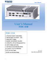
Block Diagram
RoHS Compliance
The VL-MPEe-U2 is RoHS-compliant.
ABOUT ROHS
In 2003, the European Union issued Directive 2002/95/EC regarding the Restriction of the use of
certain Hazardous Substances (RoHS) in electrical and electronic equipment.
The RoHS directive requires producers of electrical and electronic equipment to reduce to
acceptable levels the presence of six environmentally sensitive substances: lead, mercury,
cadmium, hexavalent chromium, and the presence of polybrominated biphenyls (PBB) and
polybrominated diphenyl ethers (PBDE) flame retardants, in certain electrical and electronic
products sold in the European Union (EU) beginning July 1, 2006.
VersaLogic Corp. is committed to supporting customers with high-quality products and services
meeting the European Union’s RoHS directive.
Warnings
ELECTROSTATIC DISCHARGE
Warning! Electrostatic discharge (ESD) can damage circuit boards, disk drives, and other
components. The circuit board must only be handled at an ESD workstation. If an
approved station is not available, some measure of protection can be provided by
wearing a grounded antistatic wrist strap. Keep all plastic away from the board,
and do not slide the board over any surface.
Mini PCIe Connector
12 GPIOs
15-pin
Connector J3
Transceiver
PCIe
to Quad UART
Controller
Exar XR17V354
Dual 4-Wire
COM 10-pin
Connector J1
Dual 4-wire
COM 10-pin
Connector J2
Transceiver
+3.3V Input
Power
PCIe x1 Port 0
2.5 GT/s
4-Wire RS-232/422/485
2 Ports
12 GPIOs
4-Wire RS-232/422/485
2 Ports

Introduction
After removing the board from its protective wrapper, place the board on a
grounded, static-free surface, component side up. Use an antistatic foam pad if
available.
The board should also be protected inside a closed metallic antistatic envelope
during shipment or storage.
Note: The exterior coating on some metallic antistatic bags is sufficiently conductive to
cause excessive battery drain if the bag comes in contact with the bottom side of
the board.
HANDLING CARE
Warning! Care must be taken when handling the board not to touch the exposed circuitry
with your fingers.

VL-MPEe-U2 Reference Manual 8
Physical Details
Board Layout and Mounting
VL-MPEE-U2 MOUNTING
The VL-MPEe-U2 is a full size Mini PCIe card and needs to be mounted into a full size Mini
PCIe site. On VersaLogic CPU boards, the module is secured using two nylon screws.
VersaLogic offers 2 mm nylon screws (VL-HDW-110) and 2.5 mm nylon screws (VL-HDW-
108). On non-VersaLogic CPU boards, mounting might be accomplished using a latching system.
Note: Be careful not to over tighten the nylon mounting screws. Optimum tightness is
1 lbf·in (0.1 N·m).
VL-MPEE-U2 DIMENSIONS AND CONNECTORS
The VL-MPEe-U2 complies with Mini PCIe card (full size) dimensional standards. Dimensions
are given below to help with pre-production planning and layout.
Figure 1. VL-MPEe-U2 Dimensions and Connectors
(Not to scale. All dimensions in millimeters.)
2
50.95
30.00
J2 - COM3/4
D1 D2
J1 - COM1/2
D4
J3 - GPIO
= Pin 1
V1
V2
Mount with two
2.5
mm or 2.0 mm
nylon screws
(VL
-HDW-108 or
VL
-HDW-110)

Physical Details
Table 1 provides information about the function, mating connectors, and transition cables for
VL-MPEe-U2 connectors. Page numbers indicate where a detailed pinout or further information
is available.
Table 1: Connector Functions and Interface Cables
Connector
Function Mating
Connector Transition
Cable Cable
Description
Page
J1
COM 1/2
Molex 501330-1000 vertical
1x10 1 mm “Pico-clasp”
VL-CBR-1014
12” dual-channel
serial cable;
latching 10-pin
connector to dual
D-sub (9-pin)
12
J2
COM 3/4
Molex 501330-1000 vertical
1x10 1 mm “Pico-clasp”
VL-CBR-1014
12” dual-channel
serial cable;
latching 10-pin
connector to dual
D-sub (9-pin)
12
J3
GPIO
Molex 501330-1500 vertical
1x15 1 mm “Pico-clasp”
VL-CBR-1502
12” GPIO 15-pin
VL-CBR-1502A
cable to VL-CBR-
2004B 20-pin
screw terminal
paddleboard
14
VL-CBR-2004B DIMENSIONS AND CONNECTORS
The VL-CBR-1502 cable assembly consists of the VL-CBR-1502A cable and the VL-CBR-
2004B paddleboard. The paddleboard provides a 20-pin screw terminal interface for all GPIO
lines.
Figure 2. VL-CBR-2004B Dimensions, Connectors, Jumper Blocks
Note: The jumpers on the VL-CBR-2004B must not be removed or moved. Leave all
jumpers in the positions shown in the above figure.
+
+
60.19
75.00
24.00
J4 J3 J2 J1
V1
V2
J5
V3
V4
V5
1 5
1 5
1 5
1 5
V6

Physical Details
Table 2 provides information about the function, mating connectors, and transition cables for
VL-MPEe-A1/A2 connectors. Page numbers indicate where a detailed pinout or further
information is available.
Table 2: Connector Functions and Interface Cables
Connector
Function Mating
Connector Transition
Cable Cable
Description
Page
J1
GPIO0-2
Bare wire, 18–30 AWG
—
—
14
J2
GPIO3-5
Bare wire, 18–30 AWG
—
—
14
J3
GPIO6-9
Bare wire, 18–30 AWG
—
—
14
J4
GPIO10-11
Bare wire, 18–30 AWG
—
—
14
J5
Interface to MPEe-U2
board
Molex 501189-2010 2x10
1 mm Pico-Clasp
receptacle
VL-CBR-1502A
20 position screw
terminal, 12” latching
cable to VL-CBR-
2004B
I/O board
—
Jumper Blocks
VL-MPEE-U2 JUMPERS AS-SHIPPED CONFIGURATION
All jumpers on the VL-MPEe-U2 are shipped in the out (or "storage") position, as shown in the
figure below.
Figure 3. VL-MPEe-U2 Jumper As-shipped Configuration
V1
V2
V1
1
3
5
7
2
4
6
8
V2
1
3
5
7
2
4
6
8

Physical Details
JUMPER SUMMARY
Table 3: Jumper Summary
Jumper
Block
Description As
Shipped
V1[1-2] COM1 RS-422 Rx or RS-485 Termination
In – 120 Ohm terminated
Out – Not terminated
Out
V1[3-4] COM2 RS-422 Rx or RS-485 Termination
In – 120 Ohm terminated
Out – Not terminated
Out
V1[5-6] COM3 RS-422 Rx or RS-485 Termination
In – 120 Ohm terminated
Out – Not terminated
Out
V1[7-8] COM4 RS-422 Rx or RS-485 Termination
In – 120 Ohm terminated
Out – Not terminated
Out
V2[1-2] COM1 Mode
In – RS-422/485 Mode
Out – RS-232 Mode
Out
V2[3-4] COM2 Mode
In – RS-422/485 Mode
Out – RS-232 Mode
Out
V2[5-6] COM3 Mode
In – RS-422/485 Mode
Out – RS-232 Mode
Out
V2[7-8] COM4 Mode
In – RS-422/485 Mode
Out – RS-232 Mode
Out

VL-MPEe-U2 Reference Manual 12
Interfaces and Connectors
Serial Ports
The VL-MPEe-U2 features four on-board 16550-based serial channels. All four channels are
4-wire RS-232/RS-422/RS-485 ports with baud rates up to 400 Kbps.
Connector J1 provides an interface to the COM1 and COM2 ports. Connector J2 provides an
interface to the COM3 and COM4 ports. The VL-CBR-1014 cables each provide two DB9
connectors and can be connected to both J1 and J2 for a total of four DB9 connectors.
COM PORT CONFIGURATION
All serial ports can be operated in RS-232, RS-422, or RS-485 modes. Jumper block V2 selects
the mode of each port independently. Jumper block V1 enables the RS-422/485 termination
resistor for each port independently. The termination resistor should be enabled for RS-422 and
the RS-485 endpoint station. It should be disabled for RS-232 and for RS-485 intermediate
stations.
If RS-485 mode is used, the half-duplex differential twisted pair (TxD+/RxD+ and TxD-/RxD-)
is formed by connecting both transmit and receive pairs together. For example with COM1on
VL-CBR-1014 connector DB9b, the TxD+/RxD+ signal is formed by connecting pins 7 and 8,
and the TxD-/RxD- signal is formed by connecting pins 2 and 3.
In order to enable the RS-422/485 mode the driver must be configured correctly. In Windows,
this is achieved in Driver Properties -> Port Settings for the device driver found in the Device
Manager. In Linux, the xr17v35x.c source file must be modified prior to running "make" or
compiling the driver - see line 149 or search for #define ENABLE_RS485.
3

Interfaces and Connectors
SERIAL PORT CONNECTORS
The following tables show the function of each pin of the J1 and J2 connectors, and how the
signals are routed to the DB9 connectors on the VL-CBR-1014 cable.
Table 4: J1 Serial Port Connector Pinout
VL-MPEe-U2
J1 Pin
VL-CBR-1014
Connector Pin*
Signal
RS-232 RS-422/485
1 COM1 7 RTS TxD+
2 DB9b 3 TXD TxD-
3 8 CTS RxD+
4 2 RXD RxD-
5 5 Ground Ground
6 COM2 7 RTS TxD+
7 DB9a 3 TXD TxD-
8 8 CTS RxD+
9 2 RXD RxD-
10 5 Ground Ground
Note: Pins 1, 4, 6, and 9 of each DB9 connector are not connected.
Table 5: J2 Serial Port Connector Pinout
VL-MPEe-U2
J2 Pin
VL-CBR-1014
Connector Pin*
Signal
RS-232 RS-422/485
1 COM3 7 RTS TxD+
2 DB9b 3 TXD TxD-
3 8 CTS RxD+
4 2 RXD RxD-
5 5 Ground Ground
6 COM4 7 RTS TxD+
7 DB9a 3 TXD TxD-
8 8 CTS RxD+
9 2 RXD RxD-
10 5 Ground Ground
Note: Pins 1, 4, 6, and 9 of each DB9 connector are not connected.

Interfaces and Connectors
General Purpose I/O (GPIO) Lines
The VL-MPEe-U2 provides twelve GPIO (digital I/O) lines that are independently configurable
as an input or output. GPIO inputs can be set for normal or inverted level, and optionally set to
generate an interrupt. GPIO outputs can be set to be normal HIGH or LOW state, or open drain.
There are 10K pull-up resistors to +3.3V on all GPIO lines.
VersaLogic provides a set of API calls for managing the GPIO lines. See Application
Programming Interface (API) for information.
Note: Accesses to the GPIO functions are physically made using the Exar COM port
interface driver. Under Windows, this driver can only be opened by one application at
a time, so care should be taken that any systems wishing to use the serial port interface
and GPIO interface simultaneously synchronize their access to this COM port resource
through a single application.
GPIO CONNECTOR
Connector J3 provides a vertical 1x15 1 mm Pico-Clasp connector for the GPIO interface. The
VersaLogic VL-CBR-1502 cable assembly (consisting of the VL-CBR-1502A cable and the
VL-CBR-2004B paddleboard) attaches to connector J3 to provide a 20-pin screw terminal
interface for GPIO.
Table 6 shows the pinout of the J3 connector.
Table 6: J3 GPIO Connector Pinout
J3
Pin Signal
Name
Function
1 UART_MPIO0 GPIO0
2 UART_MPIO1 GPIO1
3 UART_MPIO2 GPIO2
4 UART_MPIO3 GPIO3
5 GND Ground
6 UART_MPIO4 GPIO4
7 UART_MPIO5 GPIO5
8 UART_MPIO6 GPIO6
9 UART_MPIO7 GPIO7
10 GND Ground
11 UART_MPIO8 GPIO8
12 UART_MPIO9 GPIO9
13 UART_MPIO10 GPIO10
14 UART_MPIO11 GPIO11
15 GND * Ground
* Ground on standard products. Custom products can
be designed to make pin 15 UART_MPIO15.

Interfaces and Connectors
Table 7 shows how the GPIO signals are routed to the VL-CBR-2004B paddleboard screw
terminals.
Table 7: VL-CBR-2004B Terminal Block Pinouts
VL-CBR-2004B
J1 Pin
Signal Name
Function
5
DGND1
Ground
4
DIO1
GPIO0
3
DIO2
GPIO1
2
DGND1
Ground
1
DIO3
GPIO2
J2 Pin
5
DIO4
GPIO3
4
DGND1
Ground
3
DIO5
GPIO4
2
DIO6
GPIO5
1
DGND2
Ground
J3 Pin
5
DIO7
GPIO6
4
DIO8
GPIO7
3
DGND2
Ground
2
DIO9
GPIO8
1
DIO10
GPIO9
J4 Pin
5
DGND2
Ground
4
DIO11
GPIO10
3
DIO12
GPIO11
2
DGND2
Ground
1
DIO13
Ground
LEDs
There are two blue LEDs (D1 and D2) that can enabled by driving the active low XR17V354
MPIO 12 (D2) and MPIO 13 (D1).
A third blue LED (D4) is a power good output driven when the XR17V354 internal 1.2V
regulator is powered up.

VL-MPEe-U2 Reference Manual 16
Application Programming Interface (API)
About VersaAPI
The VersaLogic Application Programming Interface (VersaAPI) is a shared library of API calls
for reading and controlling on-board devices on certain VersaLogic products. In Microsoft
Windows they are presented as a dynamically linked library interface plus associated header file,
and under Linux as a shared library with an associated header file.
Visit the software support page to download the VersaAPI package.
Open and Close Calls
The library interface must be opened by every application that wishes to make calls into the API
and also must be closed by that same application when exiting.
VSL_Open();
Opens the VersaAPI library.
Syntax: VL_OSALIB_API unsigned long VSL_Open();
Inputs: none
Outputs: unsigned long
This call returns 0 if the open was a success and nonzero if no useable drivers
were found by the DLL. For the VL-MPEe-U2, the useable driver is the Exar
serial port driver.
VSL_Close();
Closes the VersaAPI library.
Syntax: VL_OSALIB_API void VSL_Close();
Inputs: none
Outputs: none
4

Application Programming Interface (API)
VSL_GetVersion()
Gets the version number of the VersaAPI library
Syntax: VL_OSALIB_API void VSL_GetVersion(unsigned char *Major, unsigned char
*Minor, unsigned char *Revision);
Inputs: unsigned char *Major
A pointer to the unsigned character to receive the Version Major number.
unsigned char *Minor
A pointer to the unsigned character to receive the Version Minor number.
unsigned char *Revision
A pointer to the unsigned character to receive the Version Revision number.
Outputs: none
While this function is void, the Major, Minor, and Revision versions are returned
in their respective input fields.
Digital I/O (DIO) Calls
API calls can be made to control or interrogate specific DIO channels. The following table lists
the channel, level, and direction parameter definitions used in DIO calls.
Table 8: DIO API Parameter Definitions
Parameters Value
Channel DIO_U2_CHANNEL_1 0xA0
DIO_U2_CHANNEL_2 0xA1
DIO_U2_CHANNEL_3 0xA2
DIO_U2_CHANNEL_4 0xA3
DIO_U2_CHANNEL_5 0xA4
DIO_U2_CHANNEL_6 0xA5
DIO_U2_CHANNEL_7 0xA6
DIO_U2_CHANNEL_8 0xA7
DIO_U2_CHANNEL_9 0xA8
DIO_U2_CHANNEL_10 0xA9
DIO_U2_CHANNEL_11 0xAA
DIO_U2_CHANNEL_12 0xAB
Level* DIO_CHANNEL_LOW 0x00
DIO_CHANNEL_HIGH 0x01
Direction DIO_INPUT 0x01
DIO_OUTPUT 0x00
*Level values are also the return results for
VSL_DIOGetChannelLevel.

Application Programming Interface (API)
VSL_DIOGetChannelLevel
Reads the signal level of the specified channel.
Syntax: VL_OSALIB_API unsigned char VSL_DIOGetChannelLevel(unsigned char
Channel);
Inputs: unsigned char Channel
The DIO channel number to be interrogated.
Outputs: unsigned char
Returns the state of the channel as either high (DIO_CHANNEL_HIGH) or low
(DIO_CHANNEL_LOW).
VSL_DIOSetChannelLevel
Sets the signal level of the specified channel.
Syntax: VL_OSALIB_API void VSL_DIOSetChannelLevel(unsigned char Channel,
unsigned char Level);
Inputs: unsigned char Channel
The DIO channel number to be set.
unsigned char Level
The DIO level to be set: DIO_CHANNEL_HIGH or DIO_CHANNEL_LOW.
Outputs: none
VSL_DIOSetChannelDirection
Sets the signal direction of the specified channel.
Syntax: VL_OSALIB_API void VSL_DIOSetChannelDirection(unsigned char Channel,
unsigned char Direction);
Inputs: unsigned char Channel
The DIO channel number to be set.
unsigned char Direction
The DIO direction to be set: DIO_INPUT or DIO_OUTPUT.
Outputs: none
/