Page is loading ...

IMPORTANT: Read all instructions before beginning
the conversion of the appliance.
This conversion kit is only for Canadian installations to convert
a natural gas furnace to LP/Propane gas for altitudes between
zero and 4,500 feet above sea level. To convert the unit to LP/
Propane gas for altitudes between zero and 4,500 feet above
sea level, the main gas orifices must be replaced. For higher
altitudes (between 2,000 and 4,500 feet above sea level), the
input must be de-rated by 10%. This can be done by simply
reducing the manifold pressure without changing the gas
orifices. For United States installations, the United States
conversion kit must be used. Contact your local distributor for
details on ordering the conversion kit for the United States.
The conversion shall be carried out by a manufacturer’s
authorized representative, in accordance with the
requirements of the manufacturer, provincial or territorial
authorities having jurisdiction and in accordance with the
requirements of the CAN/CGA - B149.1 or CAN/CGA -
B149.2 installation codes.
!
WARNING:
DO NOT REMOVE OR DEFACE THE ORIGINAL
RATING PLATE.
!
WARNING:
This conversion kit must be installed by a qualified
service technician in accordance with these
instructions and all codes having jurisdiction. Failure
to follow these instructions could result in serious
injury, property damage, or death. The qualified
service technician performing this work assumes
responsibility for this conversion.
LP and High Altitude LP Gas Conversion Kit
For Canadian Installations
Installation Instructions
For Model Series G6/PGF1, L1/PGC1 Gas Furnaces, and R4/PPG1 Gas/Electric Appliances
using Honeywell gas valve only
TO CONVERT THE UNIT TO LP/PROPANE
GAS FROM NATURAL GAS FOR ALTITUDES
BETWEEN ZERO AND 4,500 FEET ABOVE
SEA LEVEL
Table 1 is a detailed listing of the components in the LP gas
conversion kit. Please check the contents of the conversion
kit with that of the parts listing, and familiarize yourself with
each components.
!
CAUTION:
The gas supply shall be shut off prior to
disconnecting the electrical power, before
proceeding with the conversion.
To Turn Off the Fuel Supply to the Appliance:
1. Set the room thermostat to “OFF” or its lowest tempera-
ture setting.
2. Turn OFF the main gas supply to the appliance at the
manual valve, outside of the appliance casing.
3. Turn OFF the electrical power to the appliance.
4. Remove the control access panel / louvered door.
5. Move the appliance gas valve lever/knob to the “OFF”
position.
FOR YOUR SAFETY
WHAT TO DO IF YOU SMELL GAS
• Do not try to light any appliance.
• Do not touch any electric switch; do not use any
phone in your building.
• Immediately call your gas supplier from a neighbor’s
phone. Follow the gas supplier’s instructions.
• If you cannot reach your gas supplier, call the fire
department.
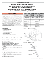
Table 1. Canadian LP/Propane
Conversion Kit Components
Description NORDYNE P/N Qty.
Installation Instructions 1
Honeywell Conversion Kit 393691 624588 1
(to convert VR8205A 2008)
Honeywell Conversion Kit 396221 624642 1
(to convert VR8205S 2288)
#54 Drill Size Burner Orifice Kit 150601 1
(contains (6) 661054
#55 Drill Size Burner Orifice Kit 150602 1
(contains (6) 661055)
#56 Drill Size Burner Orifice Kit 272221 1
(contains (7) 661056)
#57 Drill Size Burner Orifice Kit 151750 1
(contains (7) 661057)
Conversion Warning Label 703935 1
Conversion Information Label 703942 1

3
To Remove the Burner Assembly:
1. Follow the instructions “To Turn Off the Fuel Supply to the
Appliance”.
2. Disconnect the flame sensor wire from the burner box.
3. Disconnect the ignitor wires at the 2-pin plug. This is a
locking quick connect and both sides of the lower
section must be depressed in order to be separated.
4. Remove the wires from the terminals of the gas valve.
5. If present, disconnect the rubber pressure tubes from the
gas valve and the burner box. Note the pressure tubes
are present only on the sealed combustion burner box,
which is shown in Figure 2.
6. If present, remove the burner access cover plate from
the burner box. Note that the burner access cover plate
is present only on the sealed combustion burner box,
which is shown in Figure 2.
7. Remove supply gas piping from the gas valve.
8. Remove the fasteners that secure the burner box to the
heat exchanger panel and then remove the burner
assembly from the appliance, as shown in Figures 1 and
2. Keep the fasteners that were removed. Note that the
burner box may have hooks near the top of the burner
box on the right and left hand sides. To remove this type
of burner box, lift the burner box upwards and then
remove the box from the unit.
!
CAUTION:
Carefully remove the burner assembly from the
unit.
To Remove the Burner Orifices:
1. Remove the fasteners that secure the gas manifold to the
burner box, as shown in Figures 1 and 2. Carefully remove
the gas manifold assembly from the burner box. Note that
the gas manifold assembly consists of the gas valve, the
gas manifold, and the orifices.
2. Carefully remove the natural gas burner orifices from the
gas manifold, as shown in Figures 1 and 2.
!
CAUTION:
Do not re-drill the burner orifices. If the orifice size
must be changed, use only new orifices.
To Replace the Burner Orifices for LP/Propane:
1. Determine the rated input (BTU/HR) of your unit from the
rating plate. Count the number of burners in the burner
box. Use Table 2 to determine the appropriate LP orifice
for your conversion.
Table 2. Burner Orifice Sizes and Manifold Pressures
LP ORIFICE SIZE FOR
FURNACE MODEL INPUT ALTITUDES BETWEEN 0-4500 FT.
45,000 54
*G6RA/PGF1RA
60,000 55 0 TO 1,999 FEET 10.0 in w.c.
*G6RK/PGF1RK
72,000 54 2,000 TO 4,500 FEET 8.5 in w.c.
R4/PPG1
96,000 54
120,000 54
135,000 54
144,000 54
40,000 55
*G6RC/PGF1RC
60,000 55 0 TO 1,999 FEET 10.0 in w.c.
80,000 55 2,000 TO 4,500 FEET 8.5 in w.c.
100,000 55
120,000 55
72,000 54
92,000 56 0 TO 1,999 FEET 10.0 in w.c.
*G6T/PGF1T
100,000 55 2,000 TO 4,500 FEET 8.5 in w.c.
110,000 56
120,000 54
45,000 57
54,000 56 0 TO 1,999 FEET 10.0 in w.c.
*L1RA/PGC1RA
72,000 56 2,000 TO 4,500 FEET 8.5 in w.c.
90,000 56
108,000 56
126,000 56
38,000 55
*L1RC/PGC1RC
60,000 55 0 TO 1,999 FEET 9.5 in w.c.
80,000 55 2,000 TO 4,500 FEET 9.0 in w.c.
100,000 55
120,000 55
MANIFOLD
PRESSURE

4
2. Install the appropriate LP/Propane gas burner orifices into
the gas manifold. When installing the new orifices, DO NOT
use pipe joint compound on the orifice threads. Screw the
orifices into the manifold by hand until snug to eliminate
cross threading, then tighten with a wrench. Before install-
ing an orifice, check the face or side of the orifice for the drill
number to ensure that it is the appropriate size.
3. For the conversion to LP/Propane gas from natural gas, the
spring in the gas valve must be replaced. The gas valve
conversion kit (#624588) is used to convert the Honeywell
VR8205 (A,M) series gas valve only, and conversion kit
(#624642) is used to convert Honeywell valve VR8205S
2288 only. Inspect the gas valve that was removed from the
unit being converted to determine the manufacturer and
series. Then, install the appropriate gas valve conversion kit
using the instructions supplied in that kit.
!
WARNING:
Do NOT convert an appliance with a Robertshaw
Gas Valve using this kit. Robertshaw Gas Valves
require a different kit that must be ordered through
your local distributor. Contact your local distributor
for the appropriate LP/Propane conversion kit.
Instructions for Converting Honeywell Valve Part No.
VR8205S 2288 to LP/Propane Gas.
1. Turn off gas supply at the appliance service valve.
2. When converting this valve, use conversion kit part
number 624642 ONLY.
3. Remove the pressure regulator adjustment screw located
underneath the cap screw. For condensing furnaces, the
Pressure Regulator Adjustment is located underneath the
brass fitting (see Figure 3).
4. Remove the existing spring
5. Insert the replacement spring.
6. Reinstall the plastic pressure regulator adjustment screw.
7. Reinstall brass fitting if applicable.
Figure 3
Pressure Regulator Adjustment Screw on
Honeywell Gas Valve VR8205S 2288
Flame Sensor
Burner
Burner
Orifices
Gas
Manifold
On/Off
Lever
Gas Valve
Burner Box
Inlet
Pressure
Tap
Inlet
Figure 1. Typical Non-Sealed Burner Box
Figure 2. Typical Sealed Burner Box
With Access Cover Plate
Burner
Orifices
Gas
Manifold
Flame
Observation
Port
Gas
Valve
Access
Cover
Plate
Burner
Box
Inlet
Pressure
Tap
Inlet
On/Off
Lever

5
Reinstalling the Burner Assembly:
1. Reinstall the gas manifold assembly to the burner box
with the fasteners, which were removed earlier.
2. Carefully reinstall the burner box into the unit. After
installing the burner, inspect the alignment of the burn-
ers with the heat exchanger tubes. The center of the
burners should be aligned with the center of the tubes.
3. Reconnect the gas piping to the gas valve.
4. Reconnect the wires to the gas valve terminals.
5. Reconnect the rubber pressure tubes to the gas valve
and the burner box. Reinstall the burner access cover
plate. Note that this step is only for the sealed burner
box, which is shown in Figure 2.
6. Reconnect the ignitor at the 2-pin plug.
7. Reconnect the flame sensor wire to the burner box.
GAS PRESSURE ADJUSTMENT
Checking the Supply Gas Pressure
1. Turn OFF the gas supply to the unit at the manual valve
located outside of the unit.
2. With a 3/16 inch Allen wrench, remove the INLET
pressure tap plug located on the INLET side of the gas
valve, refer to Figure 3 for more details.
3. Connect a U-tube manometer to the INLET pressure tap.
4. Turn ON the main gas supply at the manual valve.
5. Check and adjust the incoming gas line pressure to 11.0-
14.0 inches WC for LP/Propane gas.
6. Turn OFF the gas supply to the unit at the manual valve
located outside of the unit.
7. Disconnect the U-tube manometer and replace the
INLET pressure tap plug. Be sure that the plug is tight
and not cross-threaded.
Lighting and Adjustment of the Appliance
1. Turn ON the gas supply to the unit at the manual valve
located outside of the unit.
2. Check all gas connections for leaks with a soap and
water solution. If the solution bubbles there is a gas leak
which must be corrected. DO NOT use an open flame to
check for gas leaks.
3. Turn ON the electrical power to the appliance.
4. Move the gas valve lever/knob to the “ON” position. The
lever/knob must be moved to the end of its range of motion
to insure the valve is completely open. Use only your hand
to push in or turn the gas control valve. Never use tools.
5. Set the room thermostat to a point above room tempera-
ture to begin the heating cycle of the unit.
6. Check that the unit ignites and operates properly. Refer
to the Installation Instructions provided with your unit for
the normal operating sequence.
7. After the flame ignites, visually inspect the burner
assembly to ensure that the flame is drawn directly
into the center of the heat exchanger tube, as shown
in Figure 5. The end of the flame will be out of sight
Inlet Pressure Tap
Inlet
Manifold
Pressure Tap
Protective
Cap
Outlet
On/Off Lever
Figure 4. Gas Valve (Honeywell VR8205 (A,M) shown)
Figure 5. Burner Inspection
around the bend of the heat exchanger tube. In a
properly adjusted burner assembly, the flame color
should be blue with some light yellow streaks near the
outer portions of the flame.
Note: Until all of the air is bled out of the gas line, the hot
surface ignitor may not ignite the gas. If the ignition
control locks out, turn the thermostat to its lowest setting
and wait one (1) minute then turn the thermostat to a point
above room temperature and the ignitor will try again to
ignite the main burners. This process may have to be
repeated several times before the burners will ignite. Once
the burners are lit, check all gas connections for leaks
again with the soap and water solution. If the solution
bubbles there is a gas leak which must be corrected. Do
not use an open flame to check for gas leaks.
Checking the Manifold Pressure
The manifold pressure must be measured by installing a
pressure gauge or U-tube manometer to the OUTLET end of
the gas valve as follows:

6
1. Turn off gas to the appliance.
2. With a 3/16 inch Allen wrench, remove the manifold
pressure tap plug located on the OUTLET side of the gas
valve. Refer to Figure 4 for more details.
3. A fitting, which has a 1/8 inch NPT pipe thread that is
compatible with the pressure gauge or U-tube
manometer, must be installed at this point.
4. Install the pressure gauge or U-tube manometer according
to the manufacturer’s supplied instructions.
5. Set the room thermostat to a point above room temperature
to start the furnace.
6. Allow the furnace to operate for three (3) minutes and
then check the manifold pressure.
7. Compare the measured value with the value shown in
Table 2. If the manifold pressure is not set to the
appropriate pressure, then it must be adjusted.
Adjusting the Manifold Pressure
1. If the manifold pressure must be adjusted, then remove
the protective cap or fitting from the top of the gas valve
regulator, as shown in Figure 3 and 4.
2. Using a short screwdriver, turn the adjustment screw to
obtain the appropriate manifold pressure determined
earlier. Note: Turning the screw clockwise increases
the pressure. Turning the screw counter-clockwise de-
creases the pressure.
3. Replace and tighten the protective cap over the adjust-
ment screw, or replace the fitting and hoses.
Removing the Pressure Gauge or U-tube Manometer
Once the manifold pressure has been properly adjusted, the
pressure gauge or U-tube manometer must be removed
from the gas valve.
1. Turn the thermostat to “OFF” or to its lowest setting.
2. Turn OFF all of the electrical power supplies to the unit.
3. Turn OFF the main gas supply to the unit at the manual
shut-off valve, which is located outside of the unit.
4. Remove the manometer adapter from the gas valve and
replace it with the 1/8 inch NPT manifold pressure plug
that had been removed earlier. Ensure that the plug is
tight and not cross-threaded.
5. Turn ON the electrical power to the unit.
6. Turn ON the main gas supply to the unit at the manual
shut-off valve, which is located outside of the unit.
7. Check all gas connections for leaks with soap and water
solution. If the solution bubbles, there is a gas leak which
must be corrected. DO NOT use an open flame to check
for gas leaks.
COMPLETING THE CONVERSION
1. Affix the conversion label (#703935) provided in the kit to
the outside of the door of the unit. Next, affix the
conversion information label (#703942) near the rating
plate on the inside of the control area of the appliance.
Finally, affix the gas valve conversion label found in the
Gas Valve Conversion Kit to the rating plate. Each label
should be prominent and visible, after installation.
2. Reinstall the appliance control panel/door.
3. Run the appliance through three complete cycles to
assure proper operation.

7082860 (Replaces 7080630 and 7080110)
Specifications and illustrations subject to change without notice and
without incurring obligations. Printed in U.S.A. (8/03)
CERTIFIED BY
(CERTIFIÉ PAR)
Les spécifications et les illustrations peuvent changer à n’importe quel moment,
sans préavis et sans obligation. Imprimé aux États-Unis d’Amérique. (8/03)
CERTIFIED BY
(CERTIFIÉ PAR)
¢708286H¤
7082860
/