Page is loading ...

Page 1
507781-02
10/2017
Supersedes 507781-01
INSTALLATION INSTRUCTIONS FOR NATURAL TO REGULATED LP/PROPANE GAS
CHANGEOVER KITS USED WITH FOAN AND TUA UNIT HEATERS
GAS CHANGEOVER KIT
GAS KITS AND
ACCESSORIES
WARNING
WARNING - This conversion kit is to be installed by a
qualied service technician or other qualied agency
in accordance with the manufacturer’s instructions,
all codes and requirements of the authority having
jurisdiction in the USA or Canada. If the information
in these instructions is not followed exactly, a re or
explosion may result causing property damage, personal
injury or loss of life. The qualied agency performing this
work assumes responsibility for this conversion.
Shipping and Packing List
Package 1 of 1 contains:
5 - Burner orices size #56 0.0465” (1.18mm) 82M93
3 - Burner orices size 0.0453” (1.15mm) 16H69
1 - White Rodgers pressure measuring adapter kit
69M1701
1 - Honeywell VR8205 series gas valve conversion
kit 48G2201
1 - White Rodgers 36 series gas valve
conversion kit 28G6101
1 - LP kit label (580051-01 82M92 / -87 16H69)
1 - Unit conversion sticker (65296600)
Application
This natural to regulated LP/propane gas changeover
kit is for use on FOAN-45,-60, -75 and TUA45S, 60S,
75S separated combustion unit heaters equipped with
the Honeywell VR8205 and White Rodgers 36 series
gas valves. See table 1.
TABLE 1
KIT APPLICATION
Cat No. Assembly Unit KBtuh
82M93 LB-115314D 45, 60, 75
16H69 LB-115314G 40
WARNING
Electric shock hazard. Can cause injury or
death. Before attempting to perform any
service or maintenance, turn the electrical
power to unit OFF at disconnect switch(es).
Unit may have multiple power supplies.
Installation
1 - Set thermostat to lowest setting. The gas supply
must be shut off prior to disconnecting the electrical
power and proceeding with the conversion.
2 - Turn automatic gas valve to OFF position.
3 - Remove the gas manifold assembly. See gure 1.
4 - Remove existing burner orices. Apply pipe thread
compound to threads of orices provided in kit.
Install orices in manifold.
IMPORTANT - Do not allow pipe thread compound to en-
ter orice bore.
5 - Install gas valve conversion kit. Refer to
manufacturer’s instruction packed in valve
conversion kit. See gures 2 and 3.
IMPORTANT - Make sure the correct conversion kit is
used for the gas valve. Use ONLY White Rodgers conver-
sion kit for White Rodgers gas valve and specic Honey-
well conversion kit for specic Honeywell gas valve ONLY.
6 - Replace the gas manifold assembly using two of
the screws removed in step 3.
7 - Connect gas supply to gas valve. Connect wiring to
gas valve. Replace wiring to ignitor electrode and
sensor electrode.
8 - Afx unit conversion sticker (provided) next to unit
rating plate.
IMPORTANT - Install gas valve changeover sticker pro-
vided in valve conversion kit to visible area of gas valve.

Page 2
BURNERS
GAS
MANIFOLD
ASSEMBLY
ORIFICES
GAS
VALV E
Figure 1
INLET
PRESSURE
TAP
1. Remove regulator cap screw and pressure regulator adjusting
scre
w.
2. Remove existing spring
.
3. Insert replacement spring.
4.
Install the new plastic pressure regulator adjustment screw so
that the top of the screw is flush (level) with the top of the
regulator. Turn the pressure regulator adjusting screw
clockwise six complete turns. This adjustment provides a
preliminary pressure setting of about 10” w.c. (2.5 kPa) for the LP
regulator.
5.
Check regulator setting either with a manometer or by
clocking the gas meter.
6. Install new cap scre
w.
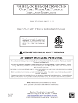
CONVERSION OF HONEYWELL VR8205 GAS
VALVE (Natural to LP)
CAP SCREW
(Black)
ADJUSTING SCREW
(Black)
SPRING
(Red)
GAS INLET
PRESSURE
REGULATOR
Figure 2
1- Remove pressure regulator adjusting cover screw.
2- Remove pressure regulator adjusting screw beneath cover
screw.
3- Remove pressure regulator spring from regulator housing.
4- Insert the stronger spring contained in this kit into the
regulator housing.
5- Replace the pressure regulator adjusting screw. Adjust outlet
pressure to heating unit manufacturer's LP specifications.
6- Replace pressure regulator adjust cover screw.
7- Attach warning label contained in envelope to gas valve
where it can be readily seen. Also attach the small round
label to top of regulator adjusting cover screw.
WHITE RODGERS 36G GAS VALVE CONVERSION
INLET
PRESSURE
PORT
MANIFOLD
PRESSURE
OUTLET
REGULATOR
COVER SCREW
Figure 3
Start-Up and Adjustment
IMPORTANT - Carefully check all piping connections. DO
NOT use matches, candles, open ame or other means
of ignition to check for gas leaks. Use a soap solution or
other preferred means.
CAUTION
Some soaps used for leak detection are corrosive to
certain metals. Carefully rinse piping thoroughly after
leak test has been completed. Do not use matches,
candles, ame or other sources of ignition to check for
gas leaks.
BEFORE LIGHTING, smell all around the appliance area
for gas. Be sure to smell next to the oor because some
gas is heavier than air and will settle on the oor.
Use only your hand to push in or turn the gas control knob.
Never use tools. If the knob will not push in or turn by
hand, do not try to repair it, call a qualied service tech-
nician. Force or attempted repair may result in a re or
explosion.
A - Placing Unit In Operation:
IMPORTANT - Follow the lighting instructions provided on
the unit. If lighting instructions are not available, see sec-
tion below.
Separated combustion unit heaters are equipped with an
automatic spark ignition system. DO NOT attempt to man-
ually light burners on these unit heaters. Each time ther-

Page 3
mostat calls for heat, the burners will automatically be lit.
1 - Make sure thermostat is set below room temperature
and power is turned off to unit.
2 - This appliance is equipped with an ignition device
which automatically lights the burners. DO NOT try
to light the burners by hand.
3 - Turn gas valve to OFF. Do not force. For Honeywell
valves, turn knob clockwise to OFF. For White
Rodgers valves, move the lever to OFF.
4 - Wait 15 minutes to clear out any gas. If you then
smell gas, immediately call your gas supplier
from an outside phone. Follow the gas supplier’s
instructions. If you do not smell gas go to next step.
5 - Turn gas valve to ON. For Honeywell gas valves,
turn the knob 90o counterclockwise to ON. For
White Rodgers valves, move the lever to ON.
6 - Turn on all electrical power to unit.
7 - Close unit door.
8 - Set thermostat to desired setting.
NOTE - When unit is initially started, steps 1 through 8
may need to be repeated to purge air from gas line.
B - Gas Pressure Adjustment
1 - Check gas line supply pressure with unit ring at
maximum rate. A minimum of 10.4” w.c. should be
maintained.
2 - After gas line pressure has been checked and
adjusted, check manifold pressure at the pressure
tap on the outlet side of the gas valve. The correct
manifold pressure for LP/propane gas is given in
table 2. Refer to gures 2 and 3 for gas manifold
pressure adjustment screw location and unit rating
plate for input value.
TABLE 2
LP/PROPANE GAS MANIFOLD PRESSURES
Input
Btuh
ALTITUDE (FT)*
0−2000 (AGA/CGA) 2000−4500 (CGA ONLY)
40 9.5” w.c. 7.2 w.c.
45/60 9.5” w.c. 9.5 w.c.
75 9.5” w.c 9.2 w.c.
*See unit installation instructions for installations at higher altitudes.
C - Burner
Start burner and allow to operate for a few minutes. Ob-
serve ame. Flame should be predominantly blue (with
some yellow), strong and steady. Flame should burn con-
tinuously from all burners.
D - Means To Verify Gas Rate
Input must not exceed amount shown on unit rating plate.
In cases where gas is not metered, the service technician
performing the conversion will need to supply the meter.
Input may then be checked by the following method:
The utility company or LP/propane gas distributor may be
contacted for the heating value of the gas. All other appli-
ances should be shut off during the input check. Locate
meter just upstream in regulated pressure (10.4” w.c. to
13.0”w.c.). To check the Btu input rate, the dial hand on
the gas meter should be timed for at least one revolution,
using the one cubic foot dial. To assure accurate mea-
surements, use temperature and pressure correction fac-
tors for the meter. To determine the number of seconds
required for the ow of one cubic foot of gas, use the fol-
lowing formula:
(BTUH CONTENT)
HEATING VALUE OF GAS X 3600
UNIT BTUH INPUT
Example: 2500 BTU gas
Unit input 45,000 BTUH
Seconds for one cubic foot =
2500 X 3600
45,000
=200 seconds
E - Ignition System
Check the normal operation sequence of the ignition sys-
tem after conversion. See instruction manual supplied
with the unit.
/