Intertherm FG7S(C,L) Installation guide

Category
Cookers
Type
Installation guide
BEFORE THE CONVERSION
IMPORTANT: Please read all instructions before
converting the furnace. Pay attention to all safety
warnings and any other special notes highlighted in the
manual. Safety markings are used frequently throughout
this manual to designate a degree or level of seriousness
and should not be ignored. WARNING indicates a
potentially hazardous situation that if not avoided, could
result in personal injury or death. CAUTION indicates a
potentially hazardous situation that if not avoided, may
result in minor or moderate injury or property damage
This conversion kit is only to be used to convert natural
gas furnaces to LP/Propane gas. This kit may only be
used in furnaces installed in altitudes between 2,000 and
10,000 feet above sea level.
Table 1 is a detailed listing of the components in the LP
gas conversion kit. Please check the contents of the
conversion kit with that of the parts listing, and familiarize
yourself with each component.
LP AND HIGH ALTITUDE LP GAS CONVERSION KIT
FOR 50 HZ FURNACES
For Model Series G7XA and G7XC Furnaces.
WARNING:
FIRE OR EXPLOSION HAZARD
• Failure to follow safety warnings exactly
could result in serious injury or property
damage.
• Installation and service must be performed
by a qualied installer, service agency or
the gas supplier.
• Do not store or use gasoline or other
ammable vapors and liquids in the
vicinity of this or any other appliance.
WHAT TO DO IF YOU SMELL GAS
• Do not try to light any appliance.
• Do not touch any electrical switch; do not
use any phone in your building.
• Leave the building immediately.
• Immediately call your gas supplier from a
neighbors phone. Follow the gas suppliers
instructions.
• If you cannot reach your gas supplier, call
the re department.
Table 1. LP Gas Conversion Kit
DESCRIPTION QTY
Installation Instructions 1
Honeywell Conversion Kit 396221
(to convert VR8205S 2288)
1
#59 Drill Size Burner Orifice Kit
(contains (7) 661059)
1
Conversion Warning Label 1
Conversion Information Label 1
WARNING:
FIRE OR EXPLOSION HAZARD
Never test for gas leaks with an open ame.
Check all connections using a commercially
available soap solution. A re or explosion
may result causing property damage, personal
injury or loss of life. Failure to follow the safety
warnings exactly could result in serious injury,
death or property damage.
WARNING:
Electrical connections must be in compliance
with local building codes, or in the absence of
local codes, with regulations established by
local electrical company. Failure to follow these
instructions could result in possible damage to
equipment, serious personal injury, or death.
WARNING:
All gas piping must conform with local building
codes, or in the absence of local codes, with
the most recent edition of the International Fuel
Gas Codes. DO NOT attempt to modify, or tap
into existing gas lines yourself. Fire or explosion
may result causing property damage, personal
injury or loss of life. Failure to follow the safety
warnings exactly could result in serious injury,
death or property damage.
INSTALLATION INSTRUCTIONS
2
CONVERTING TO LP/PROPANE GAS AT ALTITUDES
BETWEEN ZERO AND 10,000 FT.
Converting gas valves to LP/propane requires the
replacement of the burner orifices and/or the spring
found under the cap screw in the pressure regulator.
WARNING:
Shut off the gas supply at the manual gas shutoff
valve, before disconnecting the electrical power.
A re or explosion may result causing property
damage, personal injury or loss of life. Failure to
follow the safety warnings exactly could result
in serious injury, death or property damage.
WARNING:
To avoid electric shock, personal injury, or death,
turn off the electric power at the disconnect
or the main service panel before making any
electrical connections.
WARNING:
The reduction of input rating necessary for high
altitude installation may only be accomplished
with factory supplied orices. Do not attempt to
drill out orices in the eld. Improperly drilled
orices may cause re, explosion, carbon
monoxide poisoning, personal injury or death.
IMPORTANT NOTE: For altitudes between 2,000 and
10,000 feet it is required that either the orice and/
or regulator pressure to be changed. See Table 2
on page 5 to determine the correct orice size and
manifold pressure to use at different altitudes.
Removing The Burner Orices
1. Set the thermostat to the “OFF” position, or its lowest
temperature setting.
2. Shut OFF the gas supply at the manual shutoff valve
located outside of the appliance.
3. Turn off all electrical power to the appliance.
4. Remove the door from the burner compartment.
5. Move the gas valve ON/OFF switch (4) to the “OFF”
position (Figure 1).
6. Remove the wires from the terminals (3) of the gas
valve (6).
7. Remove the supply gas piping from the gas valve
inlet (5).
8. Carefully remove four screws (8) securing the gas
manifold assembly (7) to the burner assembly (9).
9. Set aside the screws (8) and remove the gas manifold
assembly (7) from the appliance.
10. Carefully remove the burner orifices (2) from the gas
manifold assembly (7).
11. Read the rating plate affixed to the appliance to deter-
mine its rated input (Btu/hr) and the size of the factory
installed orifices. NOTE: Natural Gas furnaces may
be equipped with one of three orices.
IMPORTANT NOTE: Before installing an orice, check
the face or side of the orice for the drill number to
ensure that it is the appropriate size.
12. Install the appropriate LP/Propane gas burner
orifices (2) into the gas manifold assembly (7).
NOTE: To prevent cross threading, screw the
orices (2) into the gas manifold assembly (7) by
hand until snug, then tighten with a wrench.
WARNING:
Do not use Teon tape or pipe joint compound
on the orice threads. The hole in the orice
may become blocked and cause re, explosion,
property damage, carbon monoxide poisoning,
personal injury, or death.
13. Reinstall the gas manifold assembly (7) to the burner
assembly (9) with the four screws (8), that were re-
moved earlier. NOTE: It is important that the center
of the orices (2) are aligned with the center of
the burners (1).
14. Reconnect the gas piping to the gas valve inlet (5).
15. Reconnect the wires to the gas valve terminals (3).
Figure 1. Burner and Manifold Assembly
4
3
7
6
5
1
9
2
8
3
Figure 3. Pressure Regulator Adjusting
Screw and Spring
Spring
Adjusting Screw
(VR8205S2890 shown)
Figure 2. Gas Valve Capscrew
Cap screw
(VR8205S2890 shown)
Converting To LP/Propane Gas
IMPORTANT NOTE: When converting to LP/Propane
gas from natural gas, the black spring in the gas
valve must be replaced by the red spring in the kit.
1. Remove the capscrew from the gas valve as shown
in Figure 2.
GAS PRESSURE ADJUSTMENT
Measuring the Supply Gas Pressure
1. Turn OFF the gas supply at the manual valve located
on the outside of the unit.
2. Using a 3/16 inch Allen wrench, remove the Inlet
Pressure Tap Plug located on the INLET side of the
gas valve as shown in Figure 4.
3. Install an 1/8 inch NPT pipe thread fitting, which is
compatible with a Manometer or similar pressure
gauge.
4. Connect the Manometer or pressure gauge to the Inlet
Pressure Tap.
5. Turn ON the main gas supply at the manual valve.
6. Check and adjust the incoming gas line pressure to
11.0-14.0 inches Water Column for LP/Propane gas.
7. Turn OFF the gas supply at the manual valve.
8. Disconnect the Manometer or pressure gauge.
9. Remove the NPT fitting and reinstall the INLET pres-
sure tap plug. Hand tighten the plug first to prevent
cross-threading. Tighten with 3/16 Allen wrench.
2. Remove and discard the plastic pressure regulator
adjustment screw from the gas valve as shown in
Figure 3.
3. Remove the black colored spring (Figure 3) from the
gas valve.
4. Install the red spring from the conversion kit.
5. Install the new adjusting screw from the kit.
6. Check and adjust the regulator setting. See Gas
Pressure Adjustment Section.
7. Reinstall the cap screw (Figure 2).
8. Affix the conversion label to the gas control.
Figure 4. Inlet Pressure Tap Locations
Inlet
Pressure
Tap
Lighting and Adjustment of the Appliance
1. Turn ON the manual gas valve, located on the outside
of the unit to the ON position.
WARNING:
FIRE OR EXPLOSION HAZARD
Never test for gas leaks with an open ame.
Check all connections using a commercially
available soap solution. A re or explosion
may result causing property damage, personal
injury or loss of life. Failure to follow the safety
warnings exactly could result in serious injury,
death or property damage.
2. Check all gas connections for leaks with a soap and
water solution. If the solution bubbles there is a gas
leak which must be corrected.
3. Turn on the electrical power to the appliance.
4. Move the gas valve switch to the “ON” position.
5. Set the thermostat to a point above room temperature
to begin the heating cycle of the furnace.
6. Check that the furnace ignites and operates properly.
Refer to the installation instructions provided with the
unit for the normal operating sequence.
4
7. Allow the furnace to operate for 3 minutes and then
check the manifold pressure. Compare the measured
value with the value shown in Table 2 on page 5. If
the manifold pressure is not set to the appropriate
pressure, then it must be adjusted.
Adjusting the Manifold Pressure
1. If the manifold pressure must be adjusted, remove the
capscrew from the top of the gas valve regulator, as
shown in Figure 2.
2. Using a short screwdriver, slowly turn
the adjustment screw (Figure 3) to obtain the
appropriate manifold pressure as listed in Table 2.
Note: Turning the screw clockwise increases the
pressure, turning the screw counter-clockwise
decreases the pressure. To prevent backing the
screw all the way out from the valve, turn the
screw slowly.
3. Replace and tighten the capscrew (Figure 2) over the
adjustment screw.
Removing the Manometer/Pressure Gauge
Once the manifold pressure has been properly adjusted,
the Manometer or pressure gauge must be removed from
the gas valve.
1. Turn the thermostat to its lowest setting.
2. Turn OFF the main gas supply to the unit at the manual
shut-off valve, which is located outside of the unit.
3. Turn OFF all of the electrical power supplies to the
unit.
4. Remove the pressure gauge adapter from the gas
valve and replace it with the 1/8 inch NPT manifold
pressure plug that had been removed earlier. Ensure
that the plug is tight and not cross-threaded.
5. Turn ON the electrical power to the unit.
6. Turn ON the main gas supply to the unit at the manual
shut-off valve.
COMPLETING THE CONVERSION
WARNING:
Do not alter or remove the original rating plate
from the furnace.
1. Affix the conversion warning label (P/N 703935)
provided in the kit to the outside of the unit door. Next,
affix the conversion information label (P/N 703942)
near the rating plate on the inside of the control area.
Finally, affix the gas valve conversion label found in the
Gas Valve Conversion Kit on the gas valve. Each label
should be prominent and visible after installation.
2. Reinstall the appliance door.
3. Run the appliance through three complete cycles to
assure proper operation.
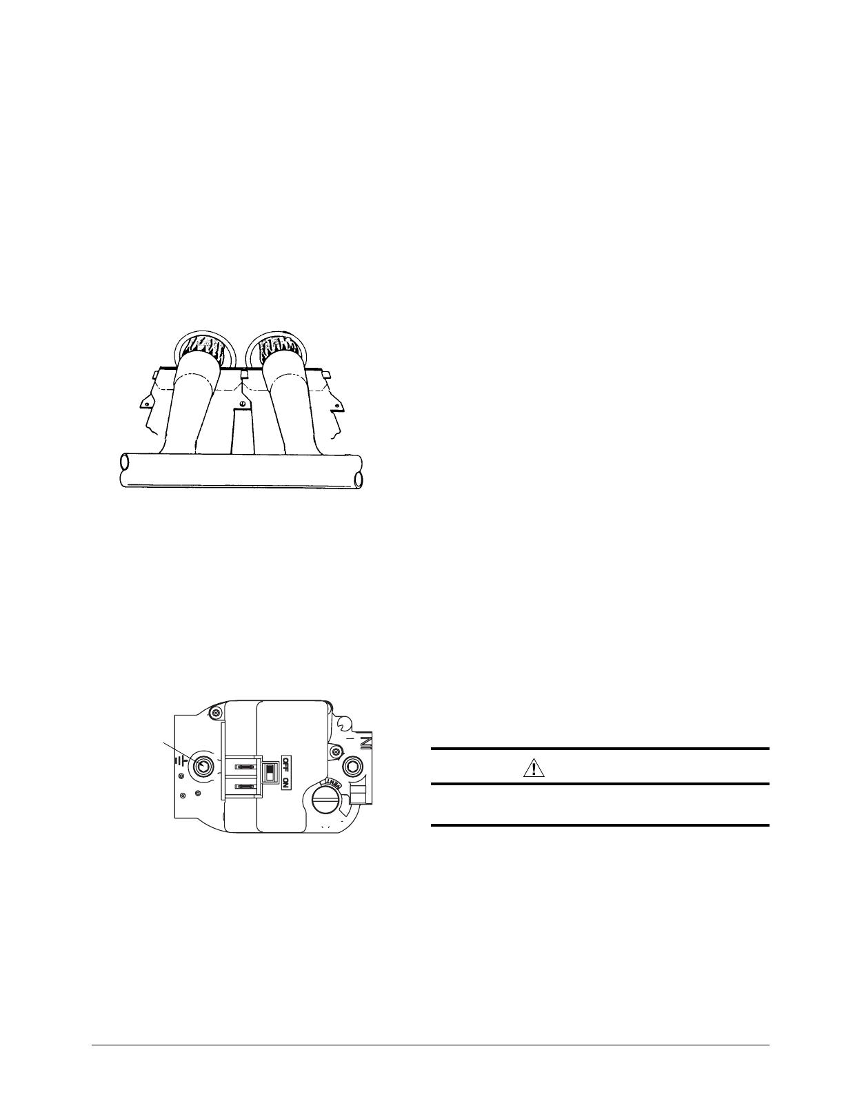
Figure 5. Burner and Manifold Assembly
7. After ignition, visually inspect the burner assembly to
ensure that the flame is drawn directly into the center
of the heat exchanger tube as shown in Figure 5. In
a properly adjusted burner assembly, the flame color
should be blue with some light yellow streaks near the
outer portions of the flame.
NOTE: Until all of the air is bled from the gas line, the
ignitor may not ignite the gas. If the ignition control locks
out, turn the thermostat to its lowest setting and wait one
minute then turn the thermostat to a point above room
temperature and the ignitor will try again to ignite the main
burners. This process may have to be repeated several
times before the burners will ignite. Once the burners
are lit, check all gas connections for leaks again with the
soap and water solution.
Measuring the Manifold Pressure
The manifold pressure must be measured by installing a
pressure gauge (Manometer, Magnehelic Meter, etc.) to
the outlet end of the gas valve as follows:
1. Turn off all electrical power to the appliance.
2. Shut OFF the gas supply at the manual shutoff valve
located outside of the appliance.
3. Using a 3/16 inch Allen wrench, remove the manifold
pressure tap plug located on the outlet side of the gas
valve as shown in Figure 6.
Figure 6. Manifold Pressure Tap Locations
Manifold
Pressure
Tap
4. Install an 1/8 inch NPT pipe thread fitting, which is
compatible with a Manometer or similar pressure
gauge.
5. Connect the Manometer or pressure gauge to the
manifold pressure tap.
6. Set the room thermostat to a point above
room temperature to start the furnace.
5
Table 2. Liquid Propane Conversion Chart
ALTITUDE ABOVE SEA LEVEL
0 to
1,999 FT
2,000 to
2,999 FT
3,000 to
4,999 FT
5,000 to
5,999 FT
6,000 to
7,999 FT
8,000 to
10,000 FT
FURNACE
MODEL
INPUT
ORIFICE
SIZE
MANIFOLD
PRESSURE
ORIFICE
SIZE
MANIFOLD
PRESSURE
ORIFICE
SIZE
MANIFOLD
PRESSURE
ORIFICE
SIZE
MANIFOLD
PRESSURE
ORIFICE
SIZE
MANIFOLD
PRESSURE
ORIFICE
SIZE
MANIFOLD
PRESSURE
G7XA
46,000 57 10.0 57 9.0 57 8.5 59 10.0 59 9.0 59 8.5
61,000 57 10.0 57 9.0 57 8.5 59 10.0 59 9.0 59 8.5
76,000 57 10.0 57 9.0 57 8.5 59 10.0 59 9.0 59 8.5
107,000 57 10.0 57 9.0 57 8.5 59 10.0 59 9.0 59 8.5
G7XC
46,000 57 10.0 57 9.0 57 8.5 59 10.0 59 9.0 59 8.5
61,000 57 10.0 57 9.0 57 8.5 59 10.0 59 9.0 59 8.5
76,000 57 10.0 57 9.0 57 8.5 59 10.0 59 9.0 59 8.5
102,000 57 10.0 57 9.0 57 8.5 59 10.0 59 9.0 59 8.5
6
7
The installer performing this work assumes all responsibility for this conversion. These instructions are primarily
intended to assist qualified individuals experienced in the proper installation of these components. Some local
codes require licensed installation/service personnel for this type of equipment. Safety should always be the
deciding factor when installing this product and using common sense plays an important role as well. Improper
installation of the components or failure to follow safety warnings could result in serious injury, death, or property
damage. After completing the installation, return these instructions to the Homeowner’s Package for owner-user’s
future reference.
7089290
Specifications & illustrations subject to change without notice or incurring obligations (07/15).
O’Fallon, MO, © Nortek Global HVAC LLC 2015. All Rights Reserved.
  • Page 1 1
  • Page 2 2
  • Page 3 3
  • Page 4 4
  • Page 5 5
  • Page 6 6
  • Page 7 7
  • Page 8 8

Intertherm FG7S(C,L) Installation guide

Category
Cookers
Type
Installation guide

Ask a question and I''ll find the answer in the document

Finding information in a document is now easier with AI