Page is loading ...

FormNo.3426-924RevC
DebrisBlower600
ModelNo.44536—SerialNo.403063082andUp
Registeratwww.Toro.com.
OriginalInstructions(EN)
*3426-924*

ThisproductcomplieswithallrelevantEuropean
directives;fordetails,pleaseseetheseparateproduct
specicDeclarationofConformity(DOC)sheet.
WARNING
CALIFORNIA
Proposition65Warning
Useofthisproductmaycauseexposure
tochemicalsknowntotheStateof
Californiatocausecancer,birthdefects,
orotherreproductiveharm.
Introduction
Thismachineisa3-pointhitch,tractor-mounted,
debrisblowerwhichisintendedtobeused
byprofessional,hiredoperatorsincommercial
applications.Itisprimarilydesignedtousewind
powertoquicklyclearlargeareasofunwanteddebris
onwell-maintainedlawnsinparks,sportselds,and
oncommercialgrounds.
Usingthisproductforpurposesotherthanitsintended
usecouldprovedangeroustoyouandbystanders.
Readthisinformationcarefullytolearnhowtooperate
andmaintainyourproductproperlyandtoavoid
injuryandproductdamage.Youareresponsiblefor
operatingtheproductproperlyandsafely.
Visitwww.Toro.comforproductandaccessory
information,helpndingadealer,ortoregisteryour
product.
Wheneveryouneedservice,genuineToroparts,or
additionalinformation,contactanAuthorizedService
DealerorToroCustomerServiceandhavethemodel
andserialnumbersofyourproductready.Writethe
numbersinthespaceprovided.
ModelNo.
SerialNo.
Thismanualidentiespotentialhazardsandhas
safetymessagesidentiedbythesafety-alertsymbol
(Figure1),whichsignalsahazardthatmaycause
seriousinjuryordeathifyoudonotfollowthe
recommendedprecautions.
g000502
Figure1
Safety-alertsymbol
Thismanualuses2wordstohighlightinformation.
Importantcallsattentiontospecialmechanical
informationandNoteemphasizesgeneralinformation
worthyofspecialattention.
Contents
Safety.......................................................................3
GeneralSafety...................................................3
SafetyandInstructionalDecals..........................3
Setup........................................................................5
1ApplyingtheEntanglementDecal....................5
2InstallingtheCasterWheels.............................6
3ConnectingtheLowerLinkArms......................7
4ConnectingtheUpperLink...............................7
5AdjustingthePTOShaftLength.......................8
6ConnectingthePTOShaft...............................9
7AdjustingtheSwayLinks.................................9
8Adjustingthe3-Point-LiftStop..........................9
9RemovingtheBlowerfromtheTractor............10
10GreasingtheBlower....................................10
ProductOverview....................................................11
Specications...................................................11
Attachments/Accessories..................................11
BeforeOperation..................................................11
BeforeOperationSafety....................................11
AdjustingtheDischargeDirection.....................12
DuringOperation.................................................12
DuringOperationSafety...................................12
OperatingTips.................................................13
AfterOperation....................................................14
AfterOperationSafety......................................14
Hauling.............................................................14
Maintenance...........................................................15
MaintenanceSafety..........................................15
RecommendedMaintenanceSchedule(s)...........15
Lubrication..........................................................16
GreasingtheMachine.......................................16
BeltMaintenance................................................17
AdjustingtheBlowerBelt..................................17
Storage...................................................................18
Troubleshooting......................................................19
©2020—TheToro®Company
8111LyndaleAvenueSouth
Bloomington,MN55420
2
Contactusatwww.Toro.com.
PrintedintheUSA
AllRightsReserved

Safety
GeneralSafety
Thisproductiscapableofthrowingobjects.Always
followallsafetyinstructionstoavoidseriouspersonal
injury.
Usingthisproductforpurposesotherthanitsintended
usecouldprovedangeroustoyouandbystanders.
•Readandunderstandthecontentsofboththis
Operator’sManualandtheoperator’smanualof
thetractionunitbeforeusingthismachine.Ensure
thateveryoneusingthisproductknowshowtouse
thismachineandthetractionunitandunderstands
thewarnings.
•Useyourfullattentionwhileoperatingthe
machine.Donotengageinanyactivitythat
causesdistractions;otherwise,injuryorproperty
damagemayoccur.
•Donotputyourhandsorfeetnearmoving
componentsofthemachine.
•Donotoperatethemachinewithoutallguards
andothersafetyprotectivedevicesinplaceand
workingonthemachine.
•Keepchildren,bystanders,andpetsoutofthe
operatingarea.Neverallowchildrentooperate
themachine.
•Alwaysshutoffthetractionunitengine,removethe
key(ifequipped),waitforallmovingpartstostop,
andallowthemachinetocoolbeforeadjusting,
repairing,cleaning,orstoringthemachine.
Improperlyusingormaintainingthismachinecan
resultininjury.Toreducethepotentialforinjury,
complywiththesesafetyinstructionsandalways
payattentiontothesafety-alertsymbol(
),which
meansCaution,Warning,orDanger—personalsafety
instruction.Failuretocomplywiththeseinstructions
mayresultinpersonalinjuryordeath.
SafetyandInstructionalDecals
Safetydecalsandinstructionsareeasilyvisibletotheoperatorandarelocatednearanyarea
ofpotentialdanger.Replaceanydecalthatisdamagedormissing.
decal93-7814
93-7814
1.Entanglementhazard,belt—stayawayfrommovingparts;
keepallguardsandshieldsinplace.
decal98-3110
98-3110
1.Warning—readtheOperator’sManualandreceivetraining.
2.Warning—wearhearingprotection.
3.Thrownobjecthazard—weareyeprotectionandkeep
bystandersawayfromthemachine.
4.Cuttinghazardofhandorfoot—waitformovingpartsto
stop.
3

decal105-0627
105-0627
1.Warning—stoptheengine,removetheignitionkeybefore
leavingthemachineanddisconnectthepowertake–off
(PTO)shaft.
decal105-0628
105-0628
1.Warning—donotoperatethemachinewithpowertake-off
(PTO)atagreateranglethan15degrees.
decal105-0668
105-0668
decal105-0669
105-0669
decal105-0698
105-0698
1.Warning—readtheOperator’sManual.
decal105-0708
105-0708
1.Warning—thrownobjecthazard;keepbystandersaway
frommachine.
decal105-0709
105-0709
1.Entanglementhazard,belt—keepallguardsandshieldsin
place;stayawayfrommovingparts.
decal133-8061
133-8061
decal138-9038
138-9038
1.Entanglementhazard—readtheOperator’sManual;stay
awayfrommovingparts;keepallguardsandshieldsin
place.
4

Setup
LooseParts
Usethechartbelowtoverifythatallpartshavebeenshipped.
ProcedureDescription
Qty.
Use
1
CEentanglementdecal
1
Applytheentanglementdecal—CE
mowers
2
Nopartsrequired
–
Installthecasterwheels.
3
Nopartsrequired
–
Connectthelowerlinkarms.
4
Nopartsrequired
–
Connecttheupperlink.
5
Nopartsrequired
–
AdjustthePTOshaftlength.
6
Nopartsrequired
–
ConnectthePTOshaft.
7
Nopartsrequired
–
Adjusttheswaylinks.
8
Nopartsrequired
–
Adjustthe3-point-liftstop.
9
Nopartsrequired
–
Removetheblowerfromthetractor.
10
Nopartsrequired
–
Greasetheblower.
MediaandAdditionalParts
Description
Qty.
Use
Operator'sManual
1
Reviewthemanualbeforeoperatingthemachine.
DeclarationofConformity
1
ForCEcompliance.
Note:Determinetheleftandrightsidesofthe
machinefromthenormaloperatingposition.
5
1
ApplyingtheEntanglement
Decal
CEMowers
Partsneededforthisprocedure:
1
CEentanglementdecal
Procedure
Important:ThisprocedureisrequiredforallCE
countriesandanywhereEnglishiscommonly
spoken.
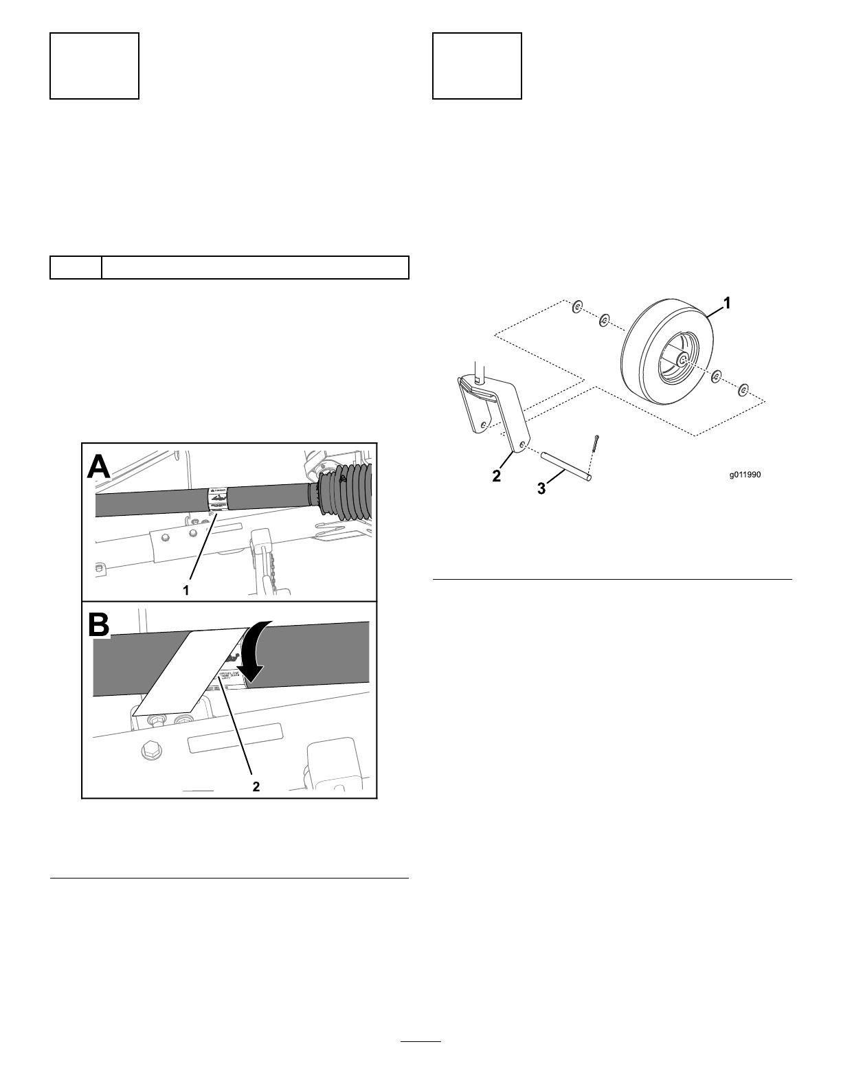
1.RotatethePTOshaftguardtoaccessthe
existingentanglementdecal(Figure2).
g262546
Figure2
1.Existingentanglement
decal
2.CEentanglementdecal
2.Cleantheexistingentanglementdecalandthe
guardareasurroundingthedecal.
3.RemovethebackingfromtheCEentanglement
decal.
4.PlacetheCEentanglementdecaloverthe
existingentanglementdecal(Figure2).
2
InstallingtheCasterWheels
NoPartsRequired
Procedure
Installacasterwheelassemblybetweeneachcaster
forkwith4washers,anaxle,and2cotterpins(Figure
3).
g011990
Figure3
1.Wheelassembly3.Axle
2.Casterfork
6
3
ConnectingtheLowerLink
Arms
NoPartsRequired
Procedure
1.Positionthebloweronaat,levelsurfaceand
disengagethePTO.
2.Backthetractorsquarelyuptothebloweruntil
thelowerlinkarmsarealignedwiththehitch
pins.
3.Engagetheparkingbrake,shutoffthetraction
unitengine,andremovethekeyfromthe
ignition.
Note:Waitforthetractionunitengineand
allmovingpartstostopbeforeleavingthe
operator’sseat.
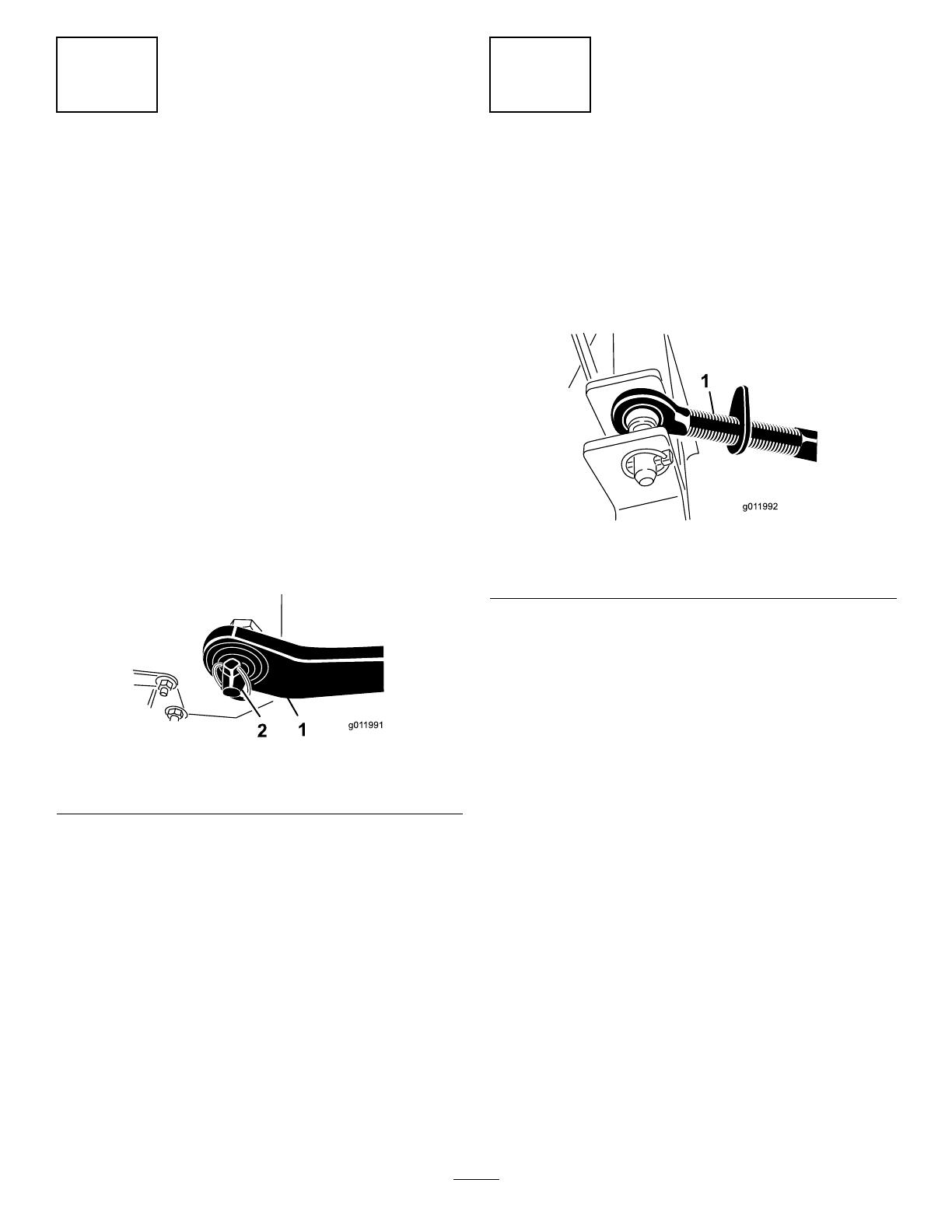
4.Inserttherightandleft,lowerlinkarmsontothe
hitchpins(Figure4).
g011991
Figure4
1.Lowerlink2.Lynchpin
5.Securethelowerlinkarmstothehitchpinswith
thelynchpins(Figure4).
4
ConnectingtheUpperLink
NoPartsRequired
Procedure
1.Connecttheupperlinktotheholesintheblower
bracketandsecureitwithaclevispinandlynch
pin(Figure5).
g011992
Figure5
1.Upperlink
2.Rotatetheadjustinglinktotightenthelink.
Note:Donotovertightentoraisethebackend
oftheblowerofftheground.
3.Tightenthelocknuttosecuretheupperlinkinto
position.
7
5
AdjustingthePTOShaft
Length
NoPartsRequired
Procedure
Important:AlongPTOshaftissuppliedwiththe
machinetoaccommodatelargevariationsinthe
tractor’sPTOand3-pointlocations.Formost
machines,thisshaftistoolongandmustbecut
tothecorrectlength,ordamagemayresult.
Important:IncorrectPTOshaftlengthcancause
machineand/orattachmentdamageandpersonal
injury.
1.Withthebloweronalevelsurface,lowerthe
bloweruntiltheinputshaftisapproximatelythe
sameheightasthetractorPTOshaft.
Note:Thisistheshortestdistancebetween
the2shafts.
2.Measurethedistancefromthelockgrooveof
thetractorPTOshafttothelockgrooveatthe
blower-inputshaft.
Note:Recordthisdimension.
3.FullycollapsethePTOshaftandmeasurethe
distancebetweenthelockpincollars.
Note:Recordthisdimension.
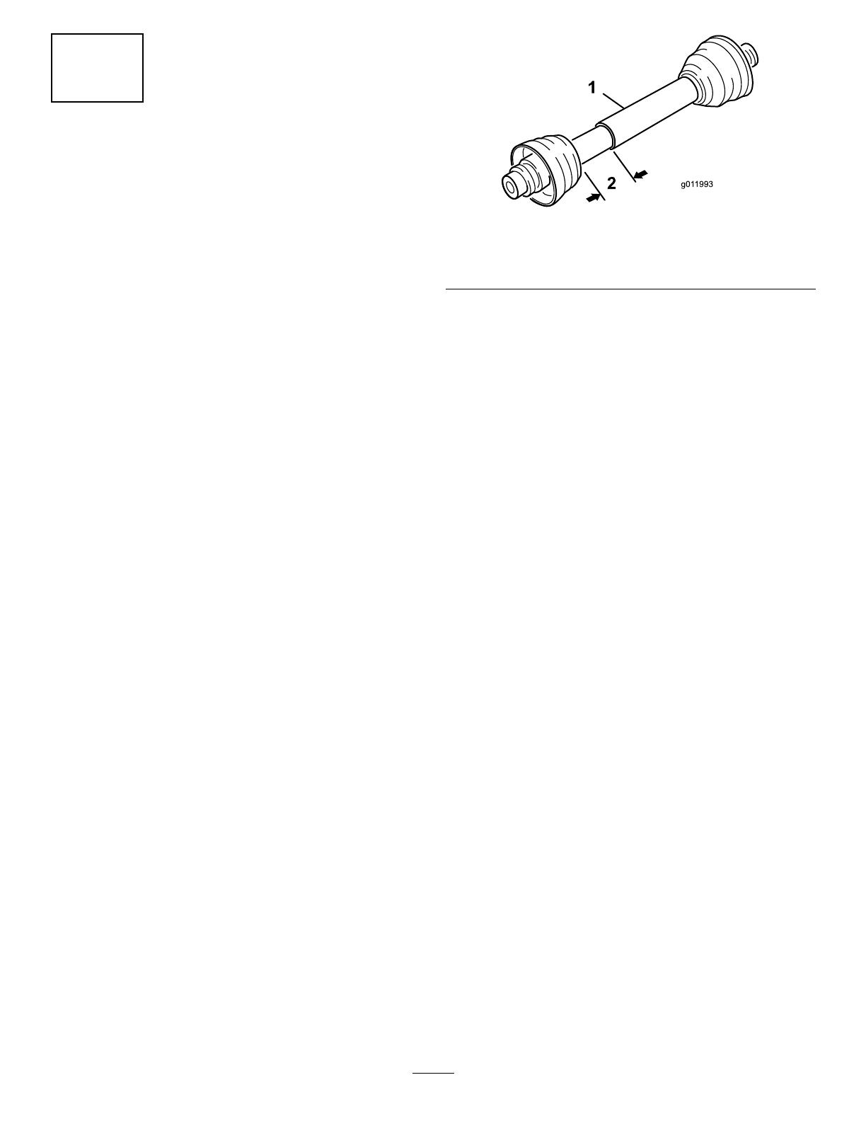
4.Attheshortestlengthoftheshaft,the2halves
ofthePTOshaftmusthaveatleast37mm
(1-1/2inches)ofadditionalclearancetocollapse
(Figure5).
Note:Ifthedimensioninstep2isnotatleast
37mm(1-1/2inches)greaterthanthedimension
instep3,thePTOshaftistoolong;proceedto
step5.Ifthereisenoughclearancetoallowthe
PTOshafttocollapse,proceedtostep10.
g011993
Figure6
1.PTOshaft2.37mm(1-1/2inches)
dimension
5.Usethefollowingcalculationtoestablish
howmuchshortertheshaftmustbe,when
connected,toensureaclearanceof37mm
(1-1/2inches):
A.Subtractthedimensionrecordedinstep3
fromthedimensionrecordedinstep2.
Note:Recordthisdimension.
B.Subtracttheresultinstep5Afrom37mm
(1-1/2inches).
Note:ThePTOshaftmustbeshortened
bythisamount.
6.Cuttheguardsandthesteeltubesshorterby
thecalculatedlength.
Note:CutbothhalvesofthePTOshaft.
7.Deburrtheendsofthesteeltubesinternallyand
externally.
8.Removealldebrisfromthetubesections.
9.Greasethesteeltubes.
10.AssemblethePTOshaftandsecureittothe
blowerandtractor.
11.Measuretheshaft.
Note:Ifitisnotatleast37mm(1-1/2inches),
repeattheprocedure.
12.Raisetheblowertothehighestposition.
Note:Theremustbeatleast75mm(3inches)
ofoverlapofthehalves.Adjustthe3-point-lift
stop,ifnecessary;referto8Adjustingthe
3-Point-LiftStop(page9).
8
6
ConnectingthePTOShaft
NoPartsRequired
Procedure
1.ConnectthePTOshafttotheblower-inputshaft.
2.ConnectthePTOshafttothereartractorPTO
shaft.
3.SlidethePTOshaftfullyforward.
4.DepressthepintosecurethePTOshaftinplace
andslidethePTOshaftbackandforthtoensure
thatitisproperlylocked.
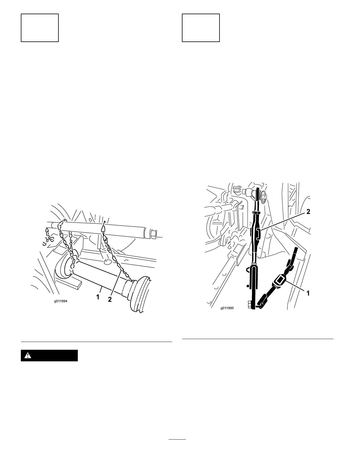
5.Connecttheguardsafetychainsfromthepower
shaftsectionstotheweldedclipsonthelink
armsortothePTOguards(Figure7).
Note:Ensurethatthechainshaveslackwhen
theblowerisraisedorlowered.
g011994
Figure7
1.PTOguard2.Safetychain
WARNING
Iftheguardchainsarenotconnected,they
couldrotateduringoperationandcause
bodilyinjury.
KeepallPTOguardsinplaceandconnectthe
guardchainstothelinkarmsorPTOguards.
7
AdjustingtheSwayLinks
NoPartsRequired
Procedure
Adjusttheswaylinksonthelowerdraftarmsof
the3-pointhitchtominimizeside-to-sideswaytoa
maximumof25mm(1inch)oneachside.
1.Adjustthelowerlinksinboarduntiltheycontact
theblowermountingplates(Figure8).
Note:Thiswillreducethestressonthepins.
Ifthetractorhasswaychainsinsteadofsway
links,installthewashersbetweenthelowerlink
armandlynchpintoreducetheoverhungload
ontheliftpins.
g011995
Figure8
1.Swaylink
2.Linkbody
2.Turntheadjustable-linkbody(ifprovided)to
raiseorlowerthelinkarmuntilthebloweris
leveledfromsidetoside(Figure8).
Note:Refertothetractoroperator’smanualfor
additionalinstallationandadjustmentprocedures.
9

8
Adjustingthe3-Point-Lift
Stop
NoPartsRequired
Procedure
Adjustandsetthe3-point-liftstoptoprovide
approximately10cm(4inches)groundclearance,
whenintheraisedposition,tominimizethePTOangle
whenraisingtheblower.Fortransportingortrailer
loading/unloading,thefull-liftrangecanbeusedas
longasthePTOtubesdonotslideapart(Figure9).
Important:OperatingthePTOinthefully-raised
positionmaydamagethePTOorother
components
Note:Refertothetractoroperator’smanualfor
adjustmentprocedures.
g011996
Figure9
1.3-point-liftstop
9
RemovingtheBlowerfrom
theTractor
NoPartsRequired
Procedure
1.Parkthemachineonalevelsurface,disengage
thePTO,engagetheparkingbrake,shutoffthe
tractionunitengine,andremovethekeyfrom
theignition.
2.Disconnecttheguardsafetychainsfromthe
tractorPTO.
Note:Securetheendofthechaintotheblower
sideofthePTOshafttopreventthePTOshaft
fromcomingapart.
3.Slowlylowerthebloweruntiltherollerand
casterwheelscontacttheground.
4.Removethelynchpinandtoplinkpinsecuring
thecenterlinktothebracket.
5.DisconnectthepowershaftfromthetractorPTO
shaft.
6.Slidethepowershaftrearwardandremoveit
fromthetractor.
7.Removethelynchpinsandslidethelowerlink
armsoffthehitchpins.
10
GreasingtheBlower
NoPartsRequired
Procedure
Beforeoperatingtheblower,lubricatethePTO
drive-shaft;refertoGreasingtheMachine(page16).
Important:Failuretoproperlygreasetheunitwill
resultinprematurefailureofcriticalparts.
10

ProductOverview
Specications
Note:Specicationsanddesignaresubjectto
changewithoutnotice.
Length
125cm(49inches)
Width
150cm(59inches)
Height
117cm(46inches)
Netweight
227kg(500lbs)
Attachments/Accessories
AselectionofT oroapprovedattachmentsand
accessoriesisavailableforusewiththemachine
toenhanceandexpanditscapabilities.Contact
yourAuthorizedServiceDealerorauthorizedT oro
distributororgotowww.T oro.comforalistofall
approvedattachmentsandaccessories.
Toensureoptimumperformanceandcontinuedsafety
certicationofthemachine,useonlygenuineToro
replacementpartsandaccessories.Replacement
partsandaccessoriesmadebyothermanufacturers
couldbedangerous,andsuchusecouldvoidthe
productwarranty.
Operation
Note:Determinetheleftandrightsidesofthe
machinefromthenormaloperatingposition.
BeforeOperation
BeforeOperationSafety
GeneralSafety
•Neverallowchildrenoruntrainedpeopleto
operateorservicethemachine.Localregulations
mayrestricttheageoftheoperator.Theowner
isresponsiblefortrainingalloperatorsand
mechanics.
•Becomefamiliarwiththesafeoperationofthe
equipment,operatorcontrols,andsafetysigns.
•Alwaysshutoffthetractionunitengine,remove
thekey,waitforallmovingpartstostop,andallow
themachinetocoolbeforeadjusting,repairing,
cleaning,orstoringthemachine.Knowhowto
stopthemachineandshutofftheenginequickly.
•Keepallguards,safetydevices,anddecalsin
place.Repairorreplaceallsafetydevicesand
replaceallillegibleormissingdecals.Donot
operatethemachineunlesstheyarepresentand
functioningproperly.
•Eachtimeanattachmentorimplementismounted,
checkthe3-point-hitchmovement.Ensurethat
thereisnointerferencewithhosesandattachment
partswhenoperatingthe3–pointhitch.
Important:YoucandamagethePTOshaft
ifyouoperateattachmentsattoohighofan
angle.
•Attachmentscanchangethestabilityandthe
operatingcharacteristicsofthetractionunit.
•Locatethepinchpointareasmarkedonthe
tractionunitandattachmentsandkeepyourhands
andfeetawayfromtheseareas.
•Ensurethatthetractionunitissuitableforusewith
animplementofthisweightbycheckingwiththe
tractionunitsupplierormanufacturer.
•Donotmodifythisequipmentinanymanner.
11

AdjustingtheDischarge
Direction
Thedirectionofthedischargeopeningcanbe
changedfromthesidetothefrontbymovingthe
controlhandle(Figure10).
g011997
Figure10
1.Dischargeopening
2.Controlhandle
DuringOperation
DuringOperationSafety
GeneralSafety
•Theowner/operatorcanpreventandisresponsible
foraccidentsthatmaycausepersonalinjuryor
propertydamage.
•Wearappropriateclothing,includingeye
protection;longpants;substantial,slip-resistant
footwear;andhearingprotection.Tiebacklong
hairanddonotwearloosejewelry.
•Donotoperatethemachinewhileill,tired,or
undertheinuenceofalcoholordrugs.
•Useyourfullattentionwhileoperatingthe
machine.Donotengageinanyactivitythat
causesdistractions;otherwise,injuryorproperty
damagemayoccur.
•Dischargedairhasconsiderableforceandcould
causeinjuryorlossoffooting.Stayawayfromthe
blowernozzlewhenthemachineisoperating.
•Keepallbystandersaway;shutoffthemachine
whenbystandersenterthearea,donotdirect
dischargetowardthem.
•Donotoperatethemachinewhenitisnot
connectedtoatowingvehicle.
•Donotrunthetractionunitengineinaconned
areawithoutadequateventilation.Engineexhaust
containscarbonmonoxide,anodorlessgasthatis
fatalifinhaled.
•Donotcarrypassengersonthemachineand
keepbystandersandpetsawayfromthemachine
duringoperation.
•Operatethemachineonlyingoodvisibilitytoavoid
holesorhiddenhazards.
•Lookbehindanddownbeforebackinguptobe
sureofaclearpath.
•Usecarewhenapproachingblindcorners,shrubs,
trees,orotherobjectsthatmayobscureyour
vision.
•Neverleavearunningmachineunattended.
•Whentransportingthemachineonpublicroads,
followalltrafcregulationsanduseanyadditional
accessoriesthatmayberequiredbylaw,suchas
lights,turnsignals,slow-movingvehicle(SMV)
signs,andothersasrequired.
•Ifthemachineevervibratesabnormally,stopthe
machineimmediately,shutoffthetractionunit
engine,removethekey,waitforallmovingpartsto
stop,andinspectfordamage.Repairalldamage
tothemachinebeforeresumingoperation.
12

•Reducespeedwhenoperatingonrough,uneven
terrain,andnearcurbs,holes,andothersudden
changesinterrain.
•Toavoidcausingthemachinetotipover,be
carefulwhenturningandavoidunsafemaneuvers.
•ForallPTOshaftsteelparts(tubes,bearings,
joints,etc.)disassemblyorrepairs,itis
highlyadvisabletocontactyourlocalToro
distributor.Removalofcomponentsforrepairs
andreassemblymaydamagesomepartsifnot
performedwithspecialtoolsbytrainedtechnicians.
•ThePTOshaftmustnotbeusedwithoutthe
guardssupplied.
SlopeSafety
•Reviewthetractionunitspecicationstoensure
thatyoudonotexceeditsslopecapabilities.
•Slopesareamajorfactorrelatedtolossofcontrol
androlloveraccidents,whichcanresultinsevere
injuryordeath.Youareresponsibleforsafeslope
operation.Operatingthemachineonanyslope
requiresextracaution.
•Evaluatethesiteconditionstodetermineifthe
slopeissafeformachineoperation,including
surveyingthesite.Alwaysusecommonsense
andgoodjudgmentwhenperformingthissurvey.
•Reviewtheslopeinstructions,listedbelow,for
operatingthemachineonslopes.Beforeyou
operatethemachine,reviewthesiteconditionsto
determinewhetheryoucanoperatethemachine
intheconditionsonthatdayandatthatsite.
Changesintheterraincanresultinachangein
slopeoperationforthemachine.
–Avoidstarting,stopping,orturningthemachine
onslopes.Avoidmakingsuddenchangesin
speedordirection.Maketurnsslowlyand
gradually.
–Donotoperateamachineunderanyconditions
wheretraction,steering,orstabilityisin
question.
–Removeormarkobstructionssuchasditches,
holes,ruts,bumps,rocks,orotherhidden
hazards.Tallgrasscanhideobstructions.
Uneventerraincouldoverturnthemachine.
–Beawarethatoperatingthemachineonwet
grass,acrossslopes,ordownhillmaycause
themachinetolosetraction.
–Useextremecautionwhenoperating
themachineneardrop-offs,ditches,
embankments,waterhazards,orother
hazards.Themachinecouldsuddenlyrollover
ifawheelgoesovertheedgeortheedge
cavesin.Establishasafetyareabetweenthe
machineandanyhazard.
OperatingTips
WARNING
Dischargedairhasconsiderableforceand
couldcauseinjuryorlossoffooting.
•Stayawayfromthedischargeopening
whenthemachineisoperating.
•Keepbystandersawayfromthedischarge
openingwhenthemachineisrunning.
1.Startthetractorandrunitatalowenginespeed.
2.EngagethePTOwhiletheengineisatidle
speed.
3.IncreasethetractorPTOspeedto540rpm.
4.Practiceblowingmaterial.
Note:Blowinthesamedirectionthatthewind
isblowingtopreventmaterialfromblowingback
intotheclearedarea.
13

AfterOperation
AfterOperationSafety
GeneralSafety
•Parkthemachineonarm,levelsurface;shutoff
thetractionunitengine,removethekey,waitfor
allmovingpartstostop,andallowthemachine
tocoolbeforeadjusting,repairing,cleaning,or
storingthemachine.
•Onlydisconnectthemachinefromthetractionunit
whileonalevelsurface.
•Whendisconnectingthemachine,alwayschock
thewheelstopreventmovement.
•Keepallpartsofthemachineingoodworking
conditionandallhardwaretightened.
•Replaceallworn,damaged,ormissingdecals.
Hauling
•Usecarewhenloadingorunloadingthemachine
intoatrailerortruck.
•Usefull-widthrampsforloadingmachineinto
trailerortruck.
•Tiethemachinedownsecurelyusingstraps,
chains,cable,orropes.Directboththefrontand
rearstrapsdownandoutwardfromthemachine.
14

Maintenance
CAUTION
Failuretoproperlymaintainthemachinecouldresultinprematurefailureofmachinesystems
causingpossibleharmtoyouorbystanders.
Keepthemachinewellmaintainedandingoodworkingorderasindicatedintheseinstructions.
Note:Determinetheleftandrightsidesofthe
machinefromthenormaloperatingposition.
MaintenanceSafety
•Beforecleaning,servicing,oradjustingthe
machine,dothefollowing:
–Parkthemachineonalevelsurface.
–Shutoffthetractionunitengine,removethe
key,andwaitforallmovingpartstostop.
–Chockthewheels.
–Allowmachinecomponentstocoolbefore
performingmaintenance.
•Performonlythosemaintenanceinstructions
describedinthismanual.Ifmajorrepairsare
everneededoryouneedassistance,contactan
authorizedT orodistributor.
•Donotrelyonahydraulicsystemtosupportthe
machine;supportthemachinewithblocksorjack
standswhenworkingbeneathit.
•Ensurethatallguardsareinstalledsecurelyafter
maintainingoradjustingthemachine.
•Donotallowuntrainedpersonneltoservicethe
machine.
•Carefullyreleasepressurefromcomponentswith
storedenergy.
•Keepallpartsingoodworkingconditionandall
fastenerstightened.Replacealldamagedor
missingdecals.
•Donotinterferewiththeintendedfunctionofa
safetydeviceorreducetheprotectionprovided
byasafetydevice.Checktheirproperoperation
regularly.
•Ifmajorrepairsareevernecessaryorassistance
isrequired,contactanauthorizedTorodistributor.
•Alteringthismachineinanymannermayaffectthe
operationofthemachine,performance,durability,
oritsusemayresultininjuryordeath.Suchuse
couldvoidtheproductwarrantyofTheT oro®
Company.
RecommendedMaintenanceSchedule(s)
MaintenanceService
Interval
MaintenanceProcedure
Every20hours
•Checkand/oradjusttheblower-belttension.
Every100hours
•Greasethefanshaftbearings.
•Greasethecasterwheelttings.
•Greasethe2drive-shaftttings.
15
Lubrication
GreasingtheMachine
Themachinehasgreasettingsthatyoumust
lubricateregularlywithNo.2lithiumgrease.
Fan-ShaftBearings
ServiceInterval:Every100hours
Greasethe2fanshaftbearings(Figure11).
Note:Removebeltcovertoaccessreartting.
g011998
Figure11
CasterWheels
ServiceInterval:Every100hours
Greasethe2casterwheelttings(Figure12).
g011999
Figure12
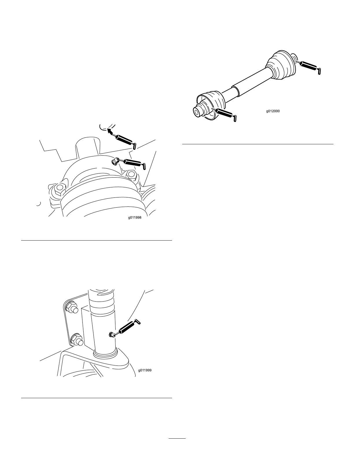
DriveShaft
ServiceInterval:Every100hours
Greasethe2drive-shaftttings(Figure13).
g012000
Figure13
16
BeltMaintenance
AdjustingtheBlowerBelt
ServiceInterval:Every20hours
Ensurethatthebeltisproperlytensionedtoensure
properoperationofthemachineandunnecessary
wear.Checkthebeltfrequently.
Important:Thefastenersonthecoversofthis
machinearedesignedtoremainonthecover
afterremoval.Loosenallofthefastenerson
eachcoverafewturnssothatthecoverisloose
butstillattached,thengobackandloosenthem
untilthecovercomesfree.Thispreventsyou
fromaccidentallystrippingtheboltsfreeofthe
retainers.
1.Removethecapscrews,washers,andnuts
securingthebeltguardtotheblowerhousing
(Figure14).
Note:Thedriveshaftdoesnothavetobe
disconnectedtoadjustthebelt.
g012001
Figure14
1.Beltguard
2.Removethebeltguard(Figure14).
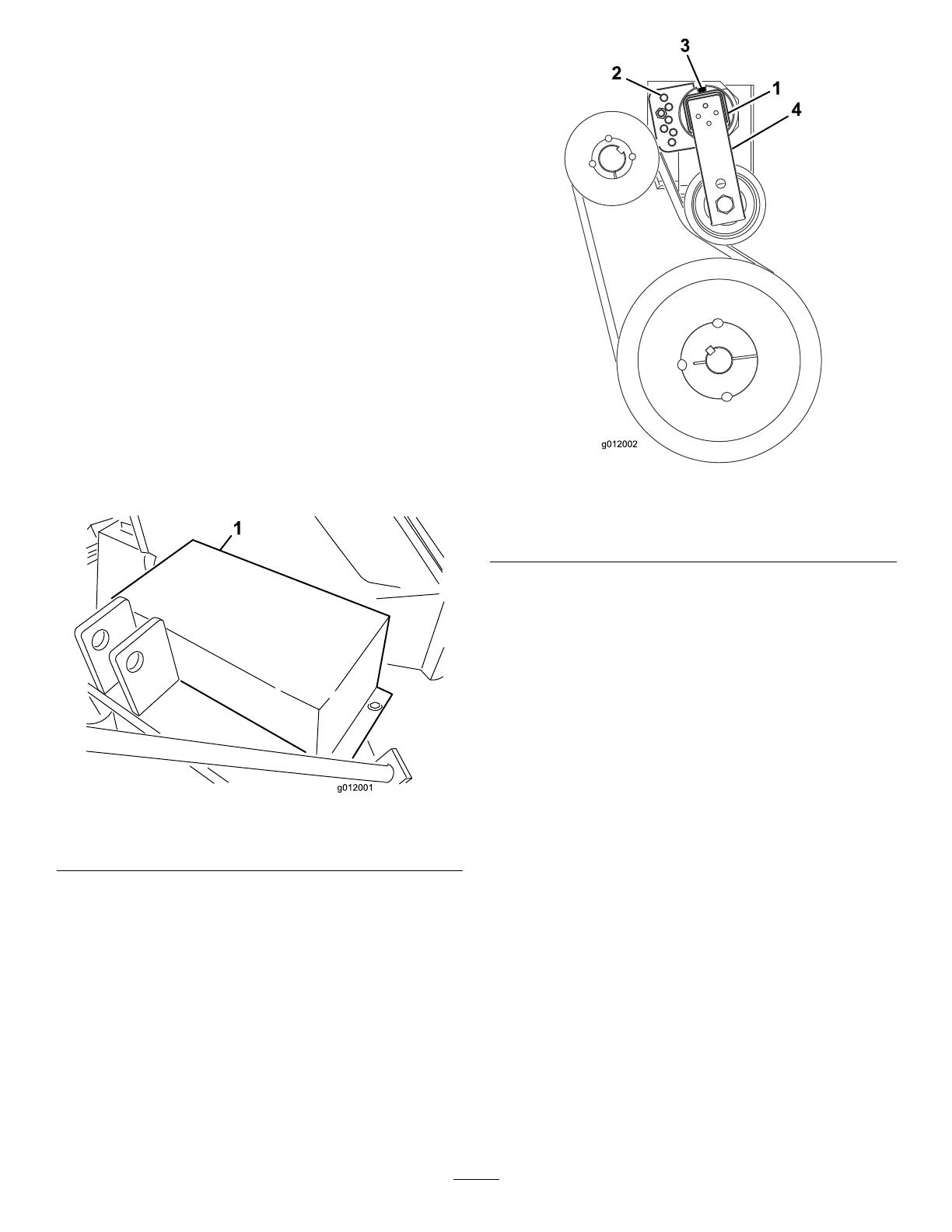
3.Removecapscrewandnutsecuringthe
tensionerguidetotheblowerframe(Figure15).
Note:Thebelttensionreleaseswhenthe
capscrewisremoved.
g012002
Figure15
1.Belt-tensionertube
3.Capscrew
2.Tensionerguide4.Idlerarm
4.Ontherearoftheframe,loosenthecapscrew
securingthebelttensionertoframe(Figure15).
5.Positionalargewrenchonthetensionerand
rotatethetensionerclockwiseuntilthedecalis
aligned15ºonthetensionertube.
6.Insertthecapscrewintothealignedguideholes
andsecureitwiththenut(Figure15).
Note:Ifholesarenotexactlyaligned,rotatethe
guidetothenexthigherholeuntilitisaligned.
7.Tightenthecapscrewontherearoftheframeto
lockthetensioner.
8.Installthebeltguardtotheblowerhousingwith
thecapscrews,washers,andnuts.
17

Storage
1.Thoroughlycleantheblower.
Note:Thefanhousingshouldbefreeofdirt,
leaves,anddebris.
2.Lubricateallgreasettings.Wipeoffanyexcess
lubricant.
3.Placealightcoatofgreaseonthesplinesofthe
PTOshaft.
4.Tightenallfasteners.
18

Troubleshooting
Problem
PossibleCauseCorrectiveAction
1.Thebearing(s)onthefanshaftis
damaged.
1.Replacethebearings.
2.Materialisbuiltuponthefanblades.2.Cleanoutanybuildupontheinside
ofthehousing.
Thereisexcessivevibration.
3.TheenginespeedofthePTOshaftis
toofast.
3.ReducethePTOspeedto540rpm.
1.Theairslotsarecloggedwithdebris.
1.Cleanoutanydebrisfromtheslots.
2.Theenginespeedonthetractoristoo
slow.
2.IncreasethePTOspeedto540rpm.
Thereislackofadequateairow.
3.Thethrottleonthetractorengineistoo
slow.
3.Makeanynecessaryrepairstobring
thetractorspeeduptonormal.
19

Notes:
/