Garmin ECHOMAP™ Plus 74sv with Transducer Installation guide
- Type
- Installation guide

ECHOMAP™ PLUS 60/70/90
SERIES
Installation Instructions
Important Safety Information
WARNING
See the Important Safety and Product Information guide in the
product box for product warnings and other important
information.
When connecting the power cable, do not remove the in-line
fuse holder. To prevent the possibility of injury or product
damage caused by fire or overheating, the appropriate fuse
must be in place as indicated in the product specifications. In
addition, connecting the power cable without the appropriate
fuse in place voids the product warranty.
CAUTION
Always wear safety goggles, ear protection, and a dust mask
when drilling, cutting, or sanding.
NOTICE
When drilling or cutting, always check what is on the opposite
side of the surface.
To obtain the best performance and to avoid damage to your
boat, install the device according to these instructions.
Read all installation instructions before proceeding with the
installation. If you experience difficulty during the installation,
contact Garmin
®
Product Support.
Tools Needed
• Drill
• Drill bits
◦ Bail mount: drill bits appropriate for the surface and
hardware
◦ Swivel mount: 3 mm (
1
/
8
in.) drill bit
◦ Flush mount: 3 mm (
1
/
8
in.) and 9.5 mm (
3
/
8
in.) drill bits
• #2 Phillips screwdriver
• Jigsaw or rotary tool
• File and sandpaper
• Marine sealant (optional)
Mounting Considerations
You can mount the device using one of three methods.
Bail mount: You can mount the device using the bail mount,
which allows you to tilt the device.
Swivel mount: You can mount the device using the swivel base
and bail mount, which allows you to swivel and tilt the device.
Not available on the ECHOMAP Plus 90 models.
Flush mount: You can mount the device in the dashboard,
which provides a more integrated installation.
Before permanently installing any part of your device, you
should plan the installation by determining the location of the
various components.
• The mounting location must provide a clear view of the
screen and access to the keys on the device.
• The mounting location must be sturdy enough to support the
device and the mount.
• The cables must be long enough to connect the components
to each other and to power.
• To avoid interference with a magnetic compass, do not install
the device closer to a compass than the compass-safe
distance value listed in the product specifications.
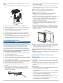
Fixed-Bail Mounting the Device
NOTICE
If you are mounting the bracket on fiberglass with screws, it is
recommended to use a countersink bit to drill a clearance
counterbore through only the top gel-coat layer. This will help to
avoid cracking in the gel-coat layer when the screws are
tightened.
Stainless-steel screws may bind when screwed into fiberglass
and overtightened. It is recommended to apply an anti-seize
lubricant on the screws before installing them.
1
Select the mounting hardware appropriate for your mounting
surface and for the bail-mount bracket.
2
Using the bail-mount bracket as a template, mark the pilot
holes through the screw holes.
3
Using a drill bit appropriate for the mounting hardware, drill
the four pilot holes.
4
Using the selected mounting hardware, secure the bail-mount
bracket to the mounting surface.
5
Install the bail-mount knobs
À
on the sides of the cradle.
6
Place the cradle into the bail-mount bracket
Á
, and tighten
the bail-mount knobs.
7
Connect each cable to a port on the cradle, using the locking
bracket or locking rings to secure the cables to the cradle
(Installing the Cables and Connectors, page 2).
Bail Mounting a Device with a Swivel Base
NOTICE
Only pan-head machine bolts or self-tapping screws should be
used to secure the swivel base. If you use screws with
countersunk heads, you may damage the mounting bracket.
Some models have the option of adding a swivel base to the bail
mount, so you can turn the device for a wider range of viewing
angles.
December 2017
190-02243-02_0B

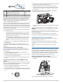
NOTE: The ECHOMAP Plus 90 models do not have a swivel
option.
1
Using the swivel base
À
as a template, mark three pilot holes
Á
.
2
Using a 3 mm (
1
/
8
in.) drill bit, drill the three pilot holes.
3
Using the included wood screws
Â
, secure the swivel base to
the mounting surface.
4
Place the bail-mount bracket
Ã
on the swivel base, and
secure it using the swivel-mount knob
Ä
.
5
Install the bail-mount knobs
Å
on the sides of the cradle.
6
Place the device in the bail-mount bracket and tighten the
bail-mount knobs.
7
Connect each cable to a port on the cradle, using the locking
bracket or locking rings to secure the cables to the cradle
(Installing the Cables and Connectors, page 2).
Flush Mounting the Device
NOTICE
Be careful when cutting the hole to flush mount the device.
There is only a small amount of clearance between the case and
the mounting holes, and cutting the hole too large could
compromise the stability of the device after it is mounted.
Using a metal pry tool such as a screwdriver can damage the
trim caps and the device. Use a plastic pry tool when possible.
You can mount the device in your dashboard using the flush-
mount template and appropriate hardware.
1
Trim the template and make sure it fits in the location where
you want to mount the device.
2
Secure the template to the mounting location.
3
Using a 9.5 mm (
3
/
8
in.) drill bit, drill one or more of the holes
inside the corners of the solid line on the template to prepare
the mounting surface for cutting.
4
Using a jigsaw or rotary cutting tool, cut the mounting surface
along the inside of the solid line indicated on the template.
5
Place the device into the cutout to test the fit.
6
If necessary, use a file and sandpaper to refine the size of
the hole.
7
If your device has trim caps, use a pry tool, such as a flat
piece of plastic or a screwdriver, to carefully pry up the
corners of the trim caps
À
, slide the pry tool to the center
Á
,
and remove the trim caps.
8
Ensure the mounting holes on the device line up with the pilot
holes on the template.
9
If the mounting holes on the device do not line up with the
pilot holes on the template, mark the new pilot-hole locations
on your template.
10
Using a 3 mm (
1
/
8
in.) drill bit, drill the pilot holes.
11
Remove the template from the mounting surface.
12
Place the device in the cradle.
NOTE: You must use the cradle and locking bracket or
locking rings when you flush-mount the device.
13
If you will not have access to the back of the device after you
mount it, connect all necessary cables to the cradle and
secure the cables with the locking bracket or locking rings
before placing the device into the cutout (Installing the
Cables and Connectors, page 2).
14
To prevent corrosion of the metal contacts, cover unused
connectors with weather caps (ECHOMAP Plus 70/90
models only).
15
Install the rubber gasket pieces on the back of the device.
The pieces of the rubber gasket have adhesive on the back.
Make sure you remove the protective liner before installing
them on the device.
16
Connect each cable to a port on the cradle, using the locking
bracket or locking rings to secure the cables to the cradle
(Installing the Cables and Connectors, page 2).
17
Place the device and cradle into the cutout.
18
Secure the device to the mounting surface using the included
screws.
19
Install the trim caps by snapping them in place around the
edges of the device.
Installing the Cables and Connectors
Wiring to Power
1
Route the power cable from the mount to the boat battery or
fuse block.
2
If necessary, extend the wires using 0.82 mm
2
(18 AWG) or
larger wire.
3
Connect the red wire to the positive terminal on the battery or
fuse block, and connect the black wire to the negative
terminal.
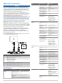
Wiring Harness
• The wiring harness is used for NMEA
®
0183 devices, and to
share route and waypoint information.
• The wiring harness connects the device to power and NMEA
0183 devices.
• The device has one internal NMEA 0183 port that is used to
connect to NMEA 0183 compliant devices.
• If it is necessary to extend the power and ground wires, you
must use 0.82 mm
2
(18 AWG) or larger wire.
• If it is necessary to extend the NMEA 0183 or alarm wires,
you must use .33 mm
2
(22 AWG) wire.
2

Item Wire Function Wire Color
À
NMEA 0183 internal port Rx (in) Brown
Á
NMEA 0183 internal port Tx (out) Blue
Â
Ground (power and NMEA 0183) Black
Ã
Power Red
Connecting to a Garmin Device to Share User Data
NOTE: This feature is not available on ECHOMAP Plus 70/90
devices. The blue and brown wires on those devices can
connect to NMEA 0183 devices only.
You can connect the ECHOMAP Plus 60 device to a compatible
Garmin device to share user data, such as waypoints. If the
devices are mounted near each other, you can connect the blue
and brown wires. If the devices are mounted too far apart for the
wires to reach, you can connect the devices using a User Data
Sharing Cable (010-12234-06).
1
Make sure both devices are connected to the same ground.
2
Complete an action:
• If the devices are mounted near each other, connect the
blue wire from the first device to the brown wire of the
second, and connect the brown wire from the first device
to the blue wire of the second.
• If the devices are not mounted near each other, obtain a
User Data Sharing Cable (010-12234-06), and connect
the devices following the instructions included with the
cable.
3
On both devices, select Nav Info > Manage Data > User
Data Sharing.
User data is shared between the connected devices. If you
select Clear User Data, data is removed from both connected
devices.
Connecting the Device to a Transducer
Go to www.garmin.com/transducers or contact your local
Garmin dealer to determine the appropriate type of transducer
for your needs.
1
Follow the instructions provided with your transducer to
correctly install it on your boat.
2
Route the transducer cable to the back of your device, away
from sources of electrical interference.
3
Connect the transducer cable to the appropriate port on the
cradle.
Connecting the Cables to the ECHOMAP Plus 60
Cradle
The connectors on the cables are keyed to fit only in the correct
ports on the ECHOMAP Plus 60 cradle. The connected cables
are held in place by a locking bracket.
1
Slide the cable locking bracket up from the bottom, and
remove the bracket from the cradle.
2
Compare the divots
À
on each cable connector to the keying
on each port to determine which cable corresponds to each
port.
3
Fully and firmly insert each cable through a hole in the cradle,
and securely connect each cable to a port.
NOTE: If the cables are not inserted far enough into the
cradle, the connectors may not connect securely to the ports,
and the device may appear to lose power or sonar or may
stop working.
4
Place the locking bracket
Á
over the cables, and slide the
bracket down to lock the cables in place.
There is an audible click when the locking bracket is installed
correctly.
Connecting the Cables to the ECHOMAP Plus 70/90
Cradle
The cables connectors fit only in the correct ports on the
ECHOMAP Plus 70/90 cradle. The connected cables are held in
place by locking rings.
1
Insert each cable into the appropriate port in the cradle.
2
Spin the locking ring clockwise to lock the cable to the cradle.
Installing the Device in the Cradle
After the cables are connected to the cradle, you can quickly
place the device in the cradle.
1
Place the base of the device in the bottom of the cradle.
2
Tilt the top of the device toward the cradle until it fastens in
place.
There is an audible click when the device is secured in the
cradle.
NOTICE
You should make sure the device is firmly secured in the cradle.
If the model uses a locking bracket, make sure the bracket is
firmly snapped shut. There is an audible click when the device
or locking bracket is installed correctly. If the device is not firmly
secured, it can lose power. The device can also fall out of the
cradle and become damaged if it is not firmly secured.
Removing the Device from the Cradle
1
Press the release lever
À
on the cradle until the device is
released.
2
Tilt the device forward, and lift it out of the cradle.
3

NMEA 2000
®
Considerations
NOTICE
If you are connecting this device to an existing NMEA 2000
network, the NMEA 2000 network should already be connected
to power. Do not connect the NMEA 2000 power cable to an
existing NMEA 2000 network, because only one power source
should be connected to a NMEA 2000 network.
If you are connecting this device to an existing NMEA 2000
network or engine network by another manufacturer, you should
install a NMEA 2000 Power Isolator (010-11580-00) between
the existing network and the Garmin devices.
If you are installing a NMEA 2000 power cable, you must
connect it to the boat ignition switch or through another in-line
switch. NMEA 2000 devices will drain your battery if the NMEA
2000 power cable is connected to the battery directly.
NOTE: NMEA 2000 is not available on all models.
NMEA 2000 compatible models can connect to a NMEA 2000
network on your boat to share data from NMEA 2000 compatible
devices such as sensors or a VHF radio. The necessary NMEA
2000 cables and connectors are sold separately.
If you are unfamiliar with NMEA 2000, you should read the
“NMEA 2000 Network Fundamentals” chapter of the Technical
Reference for NMEA 2000 Products. To download this
document, go to www.garmin.com and select Manuals on the
product page for your device.
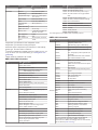
The port labeled NMEA 2000 on the cradle is used to connect it
to a standard NMEA 2000 network.
Item Description
À
NMEA 2000 compatible Garmin device
Á
NMEA 2000 drop cable
Â
NMEA 2000 power cable
Ã
Ignition or in-line switch
Ä
12 Vdc power source
Å
NMEA 2000 terminator or backbone cable
Æ
NMEA 2000 T-connector
Ç
NMEA 2000 terminator or backbone cable
Specifications
Model Specification Measurement
ECHOMAP Plus 60
series
Dimensions on cradle
and bail mount with
swivel base (W x H x
D)
259.2 x 160.8 x 65.2 mm
(10
3
/
16
x 6
5
/
16
x 2
9
/
16
in.)
Clearance to nearest
obstruction
80.0 mm (3
1
/
8
in.)
Weight 0.75 kg (1.6 lb.)
Model Specification Measurement
Display size (W x H) 137.4 x 77.3 mm (5
7
/
16
x
3
1
/
16
in.)
Display type WVGA
Display resolution 400 x 800 pixels
Max. power draw
1
12 W
Typical current draw
at 12 Vdc (RMS)
1
0.7 A
Max. current draw at
12 Vdc (RMS)
1
1.25 A
Wireless frequencies
and protocols
Wi‑Fi
®
, 2.4 GHz @ 17.2
dBm nominal
ANT+
®
, 2.4 GHz @
3.1 dBm nominal
Bluetooth
®
, 2.4 GHz @
1.2 dBm nominal
ECHOMAP Plus 70
series
Dimensions on cradle
and bail mount (W x H
x D)
259.4 x 154.3 x 63.2 mm
(10
3
/
16
x 6
1
/
16
x 2
1
/
2
in.)
Clearance to nearest
obstruction
114.7 mm (4
1
/
2
in.)
Weight 0.77 kg (1.7 lb.)
Display size (W x H) 155.1 x 86.9 mm (6
1
/
8
x
3
7
/
16
in.)
Display type WVGA
Display resolution 400 x 800 pixels
Max. power draw
1
15 W, 9 W with a GT-52
transducer
Typical current draw
at 12 Vdc (RMS)
1
0.8 A
Max. current draw at
12 Vdc (RMS)
1
1.25 A
Wireless frequencies
and protocols
Wi‑Fi, 2.4 GHz @
18.5 dBm nominal
ANT+, 2.4 GHz @
1.2 dBm nominal
Bluetooth, 2.4 GHz @
1.0 dBm nominal
ECHOMAP Plus 90
series
Dimensions on cradle
and bail mount (W x H
x D)
303.3 x 177.9 x 65.1 mm
(11
15
/
16
x 7 x 2
9
/
16
in.)
Clearance to nearest
obstruction
114.7 mm (4
1
/
2
in.)
Weight 1 kg (2.3 lb.)
Display size (W x H) 199.0 x 112.7 mm
(7
13
/
16
x 4
13
/
16
in.)
Display type WVGA
Display resolution 400 x 800 pixels
Max. power draw
1
18 W
Typical current draw
at 12 Vdc (RMS)
1
1 A
Max. current draw at
12 Vdc (RMS)
1
1.5 A
Wireless frequencies
and protocols
Wi‑Fi, 2.4 GHz @
18.5 dBm nominal
ANT+, 2.4 GHz @
1.2 dBm nominal
Bluetooth, 2.4 GHz @
1.0 dBm nominal
Sonar models Frequencies
2
Traditional: 50, 77, 83, or
200 kHz
CHIRP Garmin ClearVü:
260, 455, or 800 kHz
CHIRP SideVü: 260, 455,
or 800 kHz
Transmit power
(RMS)
1
500 W
4

Model Specification Measurement
Depth
3
701 m (2,300 ft.) at 77
kHz
All models Material Polycarbonate plastic
Water rating
4
IEC 60529 IPX7
Temperature range From -15° to 55°C (from
5° to 131°F)
Input voltage From 9 to 18 Vdc
Fuse 3 A, 125 V fast-acting
Compass-safe
distance
65 cm (25.6 in.)
NMEA 2000 LEN
5
1
NMEA 2000 draw
5
75 mA max.
Memory card 1 microSD
®
card slot; 32
GB max. card size
Max. waypoints 5,000
Max. routes 100
Max. active track
points
50,000 points, 50 saved
tracks
1
Dependent upon transducer and chartplotter model.
2
Dependent upon transducer rating and depth.
3
Maximum depth is dependent upon transducer, water salinity,
bottom type, and other water conditions.
4
The device withstands incidental exposure to water of up to 1 m
for up to 30 min. For more information, go to www.garmin.com
/waterrating.
5
NMEA 2000 not available in all models.
NMEA 2000 PGN Information
Type PGN Description
Transmit and receive 059392 ISO acknowledgment
059904 ISO request
060928 ISO address claim
126208 NMEA: Command, request, and
acknowledge group function
126996 Product information
127250 Vessel heading
128259 Speed: Water referenced
128267 Water depth
129539 GNSS DOPs
129799 Radio frequency, mode, and power
130306 Wind data
130312 Temperature
Transmit 126464 Transmit and receive PGN list group
function
127258 Magnetic Variance
129025 Position: Rapid update
129026 COG and SOG: Rapid update
129029 GNSS position data
129283 Cross track error
129284 Navigation data
129285 Navigation route and waypoint info
129540 GNSS satellites in view
Receive 127245 Rudder
127250 Vessel heading
127488 Engine parameters: Rapid update
127489 Engine parameters: Dynamic
127493 Transmission parameters: Dynamic
127498 Engine parameters: Static
127505 Fluid level
Type PGN Description
129038 AIS class A position report
129039 AIS class B position report
129040 AIS class B extended position report
129794 AIS class A static and voyage related
data
129798 AIS SAR aircraft position report
129802 AIS safety-related broadcast message
129808 DSC call information
130310 Environmental parameters
130311 Environmental parameters (obsolete)
130313 Humidity
130314 Actual pressure
130576 Small craft status
This data applies only to NMEA 2000-compatible products.
NMEA 0183 Information
Type Sentence Description
Transmit GPAPB APB: Heading or track controller
(autopilot) sentence "B"
GPBOD BOD: Bearing (origin to destination)
GPBWC BWC: Bearing and distance to waypoint
GPGGA GGA: Global positioning system fix
data
GPGLL GLL: Geographic position (latitude and
longitude)
GPGSA GSA: GNSS DOP and active satellites
GPGSV GSV: GNSS satellites in view
GPRMB RMB: Recommended minimum
navigation information
GPRMC RMC: Recommended minimum specific
GNSS data
GPRTE RTE: Routes
GPVTG VTG: Course over ground and ground
speed
GPWPL WPL: Waypoint location
GPXTE XTE: Cross track error
PGRME E: Estimated error
PGRMM M: Map datum
PGRMZ Z: Altitude
SDDBT DBT: Depth below transducer
SDDPT DPT: Depth
SDMTW MTW: Water temperature
SDVHW VHW: Water speed and heading
Receive DPT Depth
DBT Depth below transducer
MTW Water temperature
VHW Water speed and heading
WPL Waypoint location
DSC Digital selective calling information
DSE Expanded digital selective calling
HDG Heading, deviation, and variation
HDM Heading, magnetic
MWD Wind direction and speed
MDA Meteorological composite
MWV Wind speed and angle
VDM AIS VHF data-link message
You can purchase complete information about National
Marine Electronics Association (NMEA) format and
sentences from: NMEA, Seven Riggs Avenue, Severna Park,
MD 21146 USA (www.nmea.org)
5

© 2017 Garmin Ltd. or its subsidiaries
Garmin
®
and the Garmin logo are trademarks of Garmin Ltd. or its subsidiaries,
registered in the USA and other countries. ActiveCaptain
™
, ECHOMAP
™
, Garmin
ClearVü
™
, and Garmin Quickdraw
™
are trademarks of Garmin Ltd. or its subsidiaries.
These trademarks may not be used without the express permission of Garmin.
The Bluetooth
®
word mark and logos are owned by the Bluetooth SIG, Inc. and any use
of such marks by Garmin is under license. NMEA
®
, NMEA 2000
®
, and the NMEA 2000
logo are registered trademarks of the National Marine Electronics Association. NMEA
®
is
a registered trademark of the National Marine Electronics Association.
microSD
®
and the
microSD logo are trademarks of SD-3C, LLC. Wi‑Fi
®
is a registered mark of Wi-Fi
Alliance Corporation.
support.garmin.com
TRA
REGISTERED No:
ER59438/17
DEALER No:
DA0015955/08
-
 1
1
-
 2
2
-
 3
3
-
 4
4
-
 5
5
-
 6
6


Garmin ECHOMAP™ Plus 74sv with Transducer Installation guide
- Type
- Installation guide
Ask a question and I''ll find the answer in the document
Finding information in a document is now easier with AI
in other languages
Related papers
-
Garmin echoMAP™ 75sv Installation guide
-
Garmin echoMAP 43dv Installation guide
-
Garmin echoMAP™ 73sv Installation guide
-
Garmin echoMAP™ CHIRP 93sv Owner's manual
-
Garmin echoMAP™ 53cv Installation guide
-
Garmin echoMAP™ CHIRP 44dv Installation guide
-
-
Garmin ECHOMAP UHD 73sv Owner's manual
-
Garmin GPSMAP® 7412 Installation guide
-
Garmin GPSMAP® 7616xsv Owner's manual