Page is loading ...

Contents Page:
Part 4: Instructions for programming DA-Microcontrol Cl. 506
Program version: 506 B03
1. General
. . . . . . . . . . . . . . . . . . . . . . . . . . . . . . . . . . . . . . . . . . . . . . . . . 3
2. Description of the Controls
2.1 Keys on the Front Panel . . . . . . . . . . . . . . . . . . . . . . . . . . . . . . . . . . . . . . . . 4
2.2 Internal Switches . . . . . . . . . . . . . . . . . . . . . . . . . . . . . . . . . . . . . . . . . . . . 5
2.3 Display . . . . . . . . . . . . . . . . . . . . . . . . . . . . . . . . . . . . . . . . . . . . . . . . . 6
3. Description of the Function Keys
3.1 Softstart . . . . . . . . . . . . . . . . . . . . . . . . . . . . . . . . . . . . . . . . . . . . . . . . . 7
3.2 Foot Switch Mode . . . . . . . . . . . . . . . . . . . . . . . . . . . . . . . . . . . . . . . . . . . 7
3.3 Burner Settings . . . . . . . . . . . . . . . . . . . . . . . . . . . . . . . . . . . . . . . . . . . . . 8
3.4 Machine Head Rpm . . . . . . . . . . . . . . . . . . . . . . . . . . . . . . . . . . . . . . . . . . 8
3.5 Bobbin Change . . . . . . . . . . . . . . . . . . . . . . . . . . . . . . . . . . . . . . . . . . . . . 9
3.6 Resetting the Counter for the Bobbin Winder . . . . . . . . . . . . . . . . . . . . . . . . . . . . 9
3.7 Resetting the Piece Counter . . . . . . . . . . . . . . . . . . . . . . . . . . . . . . . . . . . . . 9
4. Calling up the Sewing, Service and Testing Programs
. . . . . . . . . . . . . . . . . . . . . 10
5. Base Position and Operational Readiness
. . . . . . . . . . . . . . . . . . . . . . . . . . . . 11
6. Sewing Programs
6.1 Sewing Program P01 . . . . . . . . . . . . . . . . . . . . . . . . . . . . . . . . . . . . . . . . . 12
6.2 Sewing Program P02 . . . . . . . . . . . . . . . . . . . . . . . . . . . . . . . . . . . . . . . . . 12
6.3 Sewing Program P03 . . . . . . . . . . . . . . . . . . . . . . . . . . . . . . . . . . . . . . . . . 12
6.4 Sewing Program P11 . . . . . . . . . . . . . . . . . . . . . . . . . . . . . . . . . . . . . . . . . 13
7. Service Programs
7.1 Setting the Underthread Counter . . . . . . . . . . . . . . . . . . . . . . . . . . . . . . . . . . . 14
7.2 Programming Variable rpm Ranges . . . . . . . . . . . . . . . . . . . . . . . . . . . . . . . . . 14
7.3 Burner Test: Glowing . . . . . . . . . . . . . . . . . . . . . . . . . . . . . . . . . . . . . . . . . 16
7.4 Burner Test: Lowering and Glowing . . . . . . . . . . . . . . . . . . . . . . . . . . . . . . . . . 16
7.5 Burner Test: Lowering in Stages . . . . . . . . . . . . . . . . . . . . . . . . . . . . . . . . . . . 16
7.6 Burner Test: Slow Sewing, Lowering in Stages . . . . . . . . . . . . . . . . . . . . . . . . . . . 17
8. Testing Programs
8.1 Displaying the Program Version and Check Sum . . . . . . . . . . . . . . . . . . . . . . . . . . 18
8.2 Checking the Serial Interface . . . . . . . . . . . . . . . . . . . . . . . . . . . . . . . . . . . . . 18
8.3 Memory Test and Timer Test . . . . . . . . . . . . . . . . . . . . . . . . . . . . . . . . . . . . . 19
8.4 Continuity Test . . . . . . . . . . . . . . . . . . . . . . . . . . . . . . . . . . . . . . . . . . . . . 20
8.5 Checking the Front Panel Elements . . . . . . . . . . . . . . . . . . . . . . . . . . . . . . . . . 20
8.6 Checking the Input Elements . . . . . . . . . . . . . . . . . . . . . . . . . . . . . . . . . . . . . 20
8.7 Calling Up Input Elements . . . . . . . . . . . . . . . . . . . . . . . . . . . . . . . . . . . . . . . 21
Home

Contents Page:
8.8 Calling Up Output Elements . . . . . . . . . . . . . . . . . . . . . . . . . . . . . . . . . . . . . 22
8.9 Sewing Drive: Rpm Test, Position 2 . . . . . . . . . . . . . . . . . . . . . . . . . . . . . . . . . 23
8.10 Sewing Drive: Rpm Test, Position 1 . . . . . . . . . . . . . . . . . . . . . . . . . . . . . . . . . 23
8.11 Sewing Drive: Rpm Test, Position 1, Position 2 . . . . . . . . . . . . . . . . . . . . . . . . . . 23
9. Function Displays and Error Messages
9.1 Displays of Operating Aids . . . . . . . . . . . . . . . . . . . . . . . . . . . . . . . . . . . . . . 24
9.2 Displays of Malfunctions . . . . . . . . . . . . . . . . . . . . . . . . . . . . . . . . . . . . . . . 24
9.3 Error Messages . . . . . . . . . . . . . . . . . . . . . . . . . . . . . . . . . . . . . . . . . . . . 25

1. General
The
MICROCONTROL controls
of the
DÜRKOPP ADLER 506
have
as an integral part the comprehensive
MULTITEST
testing and
monitoring system.
A microcomputer assumes the control tasks, monitors the sewing
process and displays operator errors and malfunctions.
Special programs simplify mechanical settings and make possible the
quick inspection of input and output elements without additional
measuring devices.
Errors and test results are shown in a 2 x 16 digit display.
During fault-free functioning the display shows information to the
operation and the sewing process.
With an operator error or a malfunction the function sequence is
interrupted. The cause is shown in the display by the appropriate error
symbol.
In most cases the error symbol disappears after the cause of the error
has been remedied.
In some cases the main switch must be turned off for safety reasons
while the error is being corrected.
A part of the error messages is meant only for the maintenance staff.
All functions can be called up and changed by pressing the
appropriate key. For this the unit must be in the base position.
When the unit is turned on the controls conduct a number of
comprehensive self-tests. Thereby the program and data memories
and the display, among other things, are checked as to flawless
functioning.
After the machine is turned off the set values of the individual
functions are stored in the program and data memories (battery
buffered) and automatically activated when next turned on.
3

2. Description of the Controls
2.1 Keys on the Front Panel
Key Function
Calling up sewing and testing programs
Stopping the current program
Activating the selected program
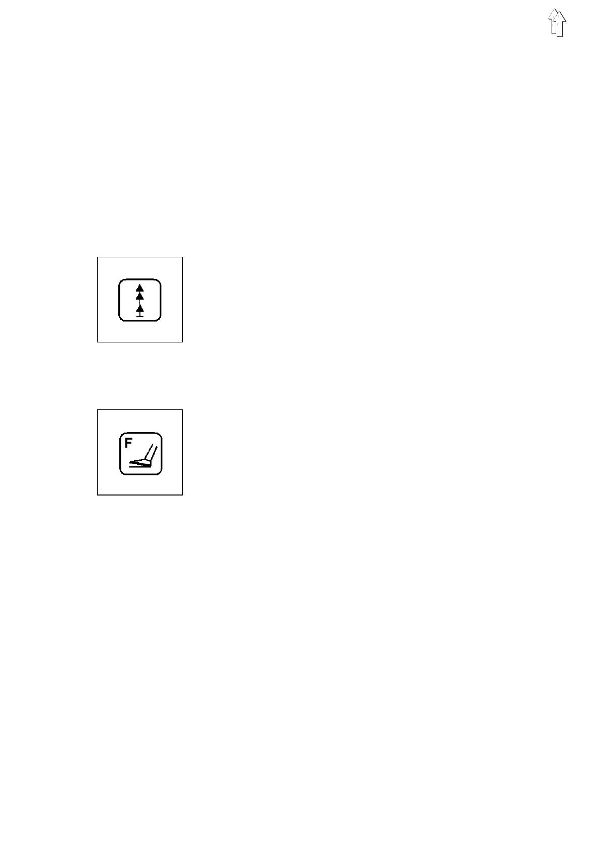
Key Function Key Function
Switching the softstart on / off Bobbin change
Setting the foot switch mode Increasing the parameter
value
Setting the burner Decreasing the parameter
value
Setting the rpm Setting the counter
4

2.2 Internal Switches
DIP switch b500
on
off
Caution Electrical Current !
Set the switch only with the main switch turned off.
DIP switch b500:
With the aid of the internal DIP switch b500 the number of stitches per
curve disk revolution is set.
The allowable settings are to be found in the following table.
Switch12345678No. of Stit.
off off off off off X Y Z 42
on off off off off X Y Z 58
off on off off off X Y Z 72
on on off off off X Y Z 84
off off on off off X Y Z 116
on off on off off X Y Z 144
off on on off off X Y Z 21
on on on off off X Y Z 29
off off off on off X Y Z 36
on off off on off X Y Z 14
off on off on off X Y Z 24
off on off on off X Y Z 168
6: X = on: needle cooling normal
6: X = off: needle cooling continuous operation
7: Y = on: without burner
7: Y = off: with burner
8: Z = on: with transport lever
8: Z = off: without transport lever
5

2.3 Display
The Microcontrol controls are equipped with a 2 x 16 digit display.
It shows the program number, machine head rpm and piece count.
With operator errors or malfunctions the function sequence is
interrupted and the cause shown by the appropriate error symbol.
The display of the piece count in the right half of the second half of the
display signals the operational readiness of the unit.
Program Number Machine Head Rpm,
Error Messages
Production Counter Piece Counter
Program number
The left half of the first line of the display shows the number of the just
selected program.
Machine head rpm / error messages
The right half of the first line of the display shows the currently set rpm
of the machine head.
By the occurance of an operator error or malfunctions the appropriate
error symbol is shown.
Production counter
The production counter shows the sum of the pieces sewn up to that
moment. It cannot be reset.
Piece counter
The piece counter shows the number of pieces sewn since the last
resetting of the counter. It can be reset to zero by pressing the "Σ" key.
When the main switch is turned off the current count of the piece
counter is stored.
If the display remains blank after the main switch is turned on
then the 1.6 A fuse (on the underside of the mains unit) is to be
replaced.
6
3. Description of the Function Keys
The values for the various functions can be set as follows:
–
Call up the desired function by pressing the appropriate function
key.
The selected function is shown in the display with a blinking cursor.
–
Change the set value with the "
+ / -
" - keys.
–
Press the same function key again.
The change is completed.
The unit is ready for operation again.
3.1 Softstart
With the softstart switched on the first stitches on the seam beginning
are sewn at reduced rpm.
The softstart is turned on and off by operating the key.
The softstart is active when the LED above the key is lit.
3.2 Foot Switch Mode
Two different foot switch modes are available.
–
Set the desired foot switch mode with the "
+
/
-
" keys.
Mode 1
(Display:
F=01
)
–
After the first operation of the right foot switch both clamps are
lowered together.
–
With the clamps lowered the sewing sequence is started by
operating the left foot switch.
–
With the second operation of the right foot switch both clamps are
raised again.
Mode 2
(Display:
F=02
)
–
Through operation of the left foot switch the left clamp is lowered.
–
Through operation of the right foot switch the lowering of the right
clamp occurs.
–
As long as only one clamp is lowered this can be raised again by a
second operation of the appropriate foot switch.
–
If both clamps are already lowered the sewing sequence is started
by operating the left foot switch.
7

3.3 Burner Settings
Two different types of burner operation are available:
–
with preheating
–
without preheating
If the sewing time necessary for the seam formation is shorter than the
heating time required by the burner the controls automatically switch
over to "with preheating".
With aid of the preheating the burner is preheated to a specific base
temperature. This reduces the time required for heating to the
operating temperature.
The sewing time required is dependent on the number of stitches per
curve disk revolution and the selected rpm.
With preheating
–
In the first line of the display the symbol "
*
" appears in front of the
machine head rpm.
–
Press the key.
"
G
" blinks in the display.
–
Set the period for the preheating with the "
+ / -
" keys ( 1 = shortest
period, 10 = longest period).
Without preheating
–
Press the key.
"
B
" blinks in the display.
–
Set the time for turning on the thread burner with the "
+ / -
" - keys
(1 = earliest switch-on time, 10 = latest switch-on time).
Note:
The earliest switch-on time means a longer glowing period.
–
Press the key again.
"
E
" blinks in the display.
–
Set the switch-off time of the thread burner with the "
+ / -
" - keys
(1 = shortest period switched on, 10 = longest period switched on).
3.4 Machine Head Rpm
With the aid of this key the machine head rpm can be set.
The rpms which can be set can be found in the table below.
–
Set the desired rpm with the "
+ / -
" - keys.
Rpm [1/min]
1400
2500
3600
4700
5800
6900
71000
81100
Attention!
At plans with a middle to large zig-zag-stitch the machine head rpm
must be lowered to a adequate level.
8

3.5 Bobbin Change
Caution Risk of Injury !
Turn the main switch off.
Change the bobbin only with the main switch turned off.
–
Press the " " key.
The machine head positions in position 3.
The bobbin can be changed.
Note:
For better accessibility by the seamstress there is a second alternative
key on the left side of the head cover of the unit.
3.6 Resetting the Counter for the Bobbin Winder
If the winding procedure is interrupted prematurely manually the
counter must be reset as follows:
–
Turn the main switch off.
–
Turn the main switch on and at the same time press the " " key.
The counter is reset to the beginning value set in program P41.
–
As long as the key is operated "
SP-RESET
" appears in the display.
3.7 Resetting the Piece Counter
The piece counter is reset to zero with this key.
The piece counter shows the number of pieces sewn since the last
resetting of the counter.
The production counter cannot be reset !
9

4. Calling Up the Sewing, Service and Testing Programs
The sewing, service and testing programs listed below are selected
with the "
Program
" selector switch.
Switch Setting Program Function
00 P00 Displays the program version
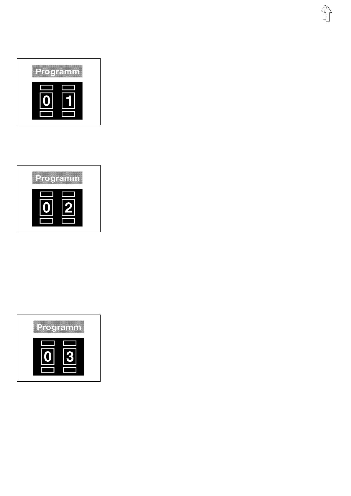
01 P01 Sewing program
02 P02 Sewing program with intermediate stop after 50% of the stitches
and opening of the right half of the clamp
03 P03 Sewing program with intermediate stop after 50% of the stitches
and opening of the left half of the clamp
11 P11 Sewing program with the rpm ranges programmed in P41
40 P40 Setting the number of bartacks per bobbin
41 P41 Program used to set the programmable rpm ranges used
in P11
42 P42 Burner test: glowing
43 P43 Burner test: lowering and glowing
44 P44 Burner test: lowering in stages
45 P45 Burner test: slow sewing, lowering in stages
58 P58 Checking the serial interface
59 P59 Timer test and memory test
60 P60 Continuity test
61 P61 Checking the front panel elements
62 P62 Checking the input elements
63 P63 Selecting input elements
64 P64 Selecting output elements
66 P66 Sewing drive: rpm test, position 2
67 P67 Sewing drive: rpm test, position 1
68 P68 Sewing drive: rpm test, position 1, position 2
–
Set the "
Program
" switch to the desired program.
–
Turn the main switch on or press the "
STOP
" key.
The selected program is activated.
–
If the symbol "
P?
" appears in the right half of the first line of the
display an invalid program number was set.
A sewing sequence running at the time the "
STOP
" key was
pressed will be interrupted.
–
Correct the setting and press the "
STOP
" key.
10

5. Base Position and Operational Readiness
Base position
–
Turn the main switch on.
–
The microcomputer checks the base position of the unit.
–
When finding an error this is shown by the appropriate symbol in
the display.
The unit can not be started.
–
Correct the error.
If the display shows "
POS2
" the unit must be turned into the 2nd
position manually with the handwheel.
–
Turn the main switch off and on again or press the "
STOP
" key.
The base position of the unit is checked again.
–
After the unit is turned on the note "
REFERENZ->
Σ" appears in the
right half of the first line of the display:
–
Press the "Σ" key.
The machine head runs into the unit’s base position.
Operational readiness
The sewing sequence can only be started when the unit is in
operational readiness.
Operational readiness is signaled by the display of the piece count in
the right half of the first line of the display.
Before the start of a sewing sequence the microcomputer permanently
checks the momentary positions of the devices.
Errors found are shown in the display.
11
6. Sewing Programs
6.1 Sewing Program P01
The exact work sequence of the sewing program P01 is described in
the Operating Instructions.
–
Set the "
Program
" switch to "
01
".
–
Press the "
STOP
" key.
The program is activated.
–
With the preheating of the burner switched on the symbol "
*
"
appears in the right half of the first line of the display in front of the
value for the machine head rpm.
With low machine head rpms the preheating is automatically
turned off. The "
*
" symbol disappears.
6.2 Sewing Program P02
–
Set the "
Program
" switch to "
02
".
–
Press the "
STOP
" key.
The program is activated.
Difference to P01:
–
After completing 50% of the number of stitches the sewing drive
stops in position 2.
The right half of the clamp is raised.
In this position, for example, lables to be sewn into the material
can be aligned.
–
Operate the right foot switch.
The right half of the clamp is lowered.
Through renewed operation of the right foot switch the right half of
the clamp can be raised again.
–
With the right half of the clamp lowered operate the left foot switch.
The sewing sequence is started again.
6.3 Sewing Program P03
–
Set the "
Program
" switch to "
03
".
–
Press the "
STOP
" key.
The program is activated.
Difference to P02:
–
At the intermediate stop in position 2 the left half of the clamp is
raised.
12

6.4 Sewing Program P11
–
Set the "
Program
" switch to "
11
".
–
Press the "
STOP
" key.
The program is activated.
Difference to P01:
–
The constant machine head rpm selected for the entire seam
before starting work is replaced by rpm ranges which are
programmed in the
P41
setting program.
This makes it possible to adjust the speed profile individually to the
seam pattern. The current machine head rpm is shown in the
display, and is also tagged with a preceding symbol for the
variable machine head rpm.
–
Pressing the "
n
" key to set the machine head rpm has no effect in
this program.
–
Altering the number of stitches per cam-disc revolution
automatically erases the programmed rpm ranges for the old
number of stitches.
The number of stitches of the cam-disc is displayed with a
preceding "?".
–
Press the "Σ" key to leave this display.
–
The "=> P41 !" prompt appears.
This is to remind the user that the
P41
program must be used to
program new rpm ranges.
–
Turn the "
Program
" switch to "
41
"
–
Press the "
STOP
" key.
Program 41 is activated (see section 7.2)
13

7. Service Programs
7.1 Setting the Underthread Counter
Program P40 sets the number of pieces which can be sewn per bobbin.
–
Set the "
Program
" switch to "
40
".
–
Press the "
STOP
" key.
The program is activated.
In the display, next to the bobbin symbol, the set value appears.
–
Set the desired value with the "
+ / -
" - keys.
(input = e.g. 0020)
–
The cursor can be moved to different positions with the "Σ" key.
7.2 Programming variable rpm ranges
Up to 6 different rpm ranges can be programmed in Program P41. The
programmed rpm ranges are only executed in sewing program P11.
–
Set the "
Program
" switch to "
41
".
–
Press the "
STOP
" key.
The program is activated.
Programming rpm ranges can be carried out in two different ways:
–
Programming in single-stitch mode.
The display is as follows: S+1 +> Sx-Sy
This process should be used if no rpm ranges have yet been
assigned to the seam pattern.
–
Programming in range-specifying mode.
The display is as follows: S+1 <+ Sx-Sy
This process should be used if rpm ranges have already been
assigned to the seam pattern.
Press the "+" key to toggle between the two modes.
–
Press the "Σ" key to invoke the selected programming mode.
Programming in single-stitch mode
Setting the first rpm range
–
The machine head rpm "n" flashes in the display.
Set the required initial value for the machine head rpm with the
"
+/-
" keys.
Caution Risk of Injury !
Do not reach into the machine while it is in operation.
–
Press the "Σ" key and hold it down until the number of completed
stitches after which a new machine head rpm is to take effect
appears in the display. As long as the "Σ" key is held down the
stitches are executed and the number of completed stitches is
increased.
As soon as the "Σ" key is released the machine head rpm set is
saved for the range in question.
14

Setting the second rpm range, at maximum up to the sixth one
–
The machine head rpm "n" flashes in the display.
Set the required initial value for the machine head rpm with the
"
+/-
" keys.
–
Press the "Σ" key and hold it down until the number of completed
stitches after which a new machine head rpm is to take effect
appears in the display. As long as the "Σ" key is held down the
stitches are executed and the number of completed stitches is
increased.
As soon as the "Σ" key is released the machine head rpm set is
saved for the range in question.
–
When the indicated stitch number (S) is reached, the
previously-programmed rpm ranges are saved.
There is then an automatic return to the start of program
P41
.
Attention:
If the value of the currently conducted individual stitches is less
than "4" or greater than/equal to the result of "number of stitches-2",
then
no
new machine head speed "n" can be set with the aid of the
"
+/-
" keys. These values are indicated in that they are shown blinking
in the display and the machine head speed does
not
blink.
Programming in range-specifying mode
ATTENTION!
In order to ensure trouble-free operation in sewing program P11,
programming must always encompass the entire stitch-number range.
Setting the first rpm range:
–
The cursor flashes in the terminal value of the stitch-number range.
The cursor can be moved with the "Σ" key.
The value at the cursor position can be changed with the "
+/-
" keys.
–
Once the required terminal value of the stitch-number range has
been set, switch to rpm setting by pressing the "
n
" key.
The machine head rpm "n" flashes in the display.
Set the machine head rpm with the "
+/-
" keys.
–
Confirm the rpm range set by pressing the "Σ" key.
–
The terminal value of the rpm range is increased by one to form
the starting value of the next rpm range.
Setting the second to sixth rpm ranges:
–
These are programmed in the same way as the first rpm range.
–
Care must be taken that the terminal value of each stitch-number
range is between the starting value and the highest stitch number.
–
Input is terminated when the highest stitch number is entered as a
terminal value.
There is then an automatic return to the start of program
P41
.
Attention:
If the final value of the stitch number range is less than "4" or greater
than/equal to the result of "number of stitches-2", then
no
new
machine head speed "n" can be set with the aid of the "
+/-
" keys.
In the first case no change over to the speed setting ocours after the
"
n
" key is operated. Instead, the value "
0004
" is shown in the display
as the final value of the stitch number range. In the second case there
is also
no
change over to the speed setting after the "
n
" key is
operated. Instead, the "number of stitches" is shown in the display as
the final value of the stitch number range.
15

7.3 Burner Test: Glowing
Caution Risk of Injury !
Danger of Burns !
During the burner test keep hands clear of the area of the glowing
burner.
–
Set the "
Program
" switch to "
42
".
–
Press the "
STOP
" key.
The program is activated.
–
"
B-TEST->
Σ" appears in the right half of the second line of the
display.
The set number of stitches per curve disk revolution (e.g. S = 72)
appears in the right half of the first line of the display .
–
Press the "Σ" key.
The burner is turned on for a short period.
7.4 Burner Test: Lowering and Glowing
Caution Risk of Injury !
Danger of Burns !
During the burner test keep hands clear of the area of the glowing
burner.
–
Set the "
Program
" switch to "
43
".
–
Press the "
STOP
" key.
The program is activated.
–
"
B-TEST->
Σ" appears in the right half of the second line of the
display.
In the right half of the first line of the display the set number of
stitches per curve disk revolution (e.g. S = 72) appears.
–
Press the "Σ" key.
The burner is turned on.
A sequence as at the seam end is run through.
7.5 Burner Test: Lowering in Stages
–
Set the "
Program
" switch to "
44
".
–
Press the "
STOP
" key.
The program is activated.
–
"
B-TEST->
Σ" appears in the right half of the second line of the
display.
In the right half of the first line of the display the set number of
stitches per curve disk revolution (e.g. S = 72) appears.
–
Press the "Σ" key repeatedly.
With each operation of the key the sequence as at the seam end is
run through in stages.
The burner remains shut off hereby.
16

7.6 Burner Test: Slow Sewing, Lowering in Stages
–
Set the "
Program
" switch to "
45
".
–
Press the "
STOP
" key.
The program is activated.
–
"
B-TEST->
Σ" appears in the right half of the second line of the
display.
In the right half of the first line of the display the set number of
stitches per curve disk revolution (e.g. S = 72)appears.
–
Press the "Σ" key.
The unit sews slowly to the seam end.
–
Press the "Σ" repeatedly.
With each operation of the key the sequence as at the seam end is
run through in stages (see program P44).
The burner remains shut off hereby.
17

8. Testing Programs
8.1 Displaying the Program Version and Check Sum
The display shows in succession the program version and a check
sum.
e.g.:
Dürkopp Adler AG
506A01 5CA9
506 = Class designation of the unit
A01 = Identification letter and serial number
5CA9= Check sum
By program versions with the same class designation and the same
identification letter the higher version replaces all lower versions
(Example: 506V03 replaces 506V01 and 506V02).
The check sum is meant only for the factory service staff.
It allows experts to see if the program memory (EPROM) of the unit
controls flawlessly contains the complete program.
–
Set the "
Program
" switch to "
00
".
–
Press the "
STOP
" key.
The program is activated.
8.2 Checking the Serial Interface
Program P58 checks the SIO component of the controls.
–
Plug the SIO testing plug into the socket b109 on the main board.
The testing plug connects the transmitter with the receiver.
In this manner a test of the loop is possible.
–
Set the "
Program
" switch to "
58
".
–
Press the "
STOP
" key.
The program is activated.
Display Explanation
OK
SIO component is okay
Err
SIO component is defective,
SIO testing plug is not in place
no SIO
Controls are being run without SIO
18

8.3 Memory Test and Timer Test
ATTENTION !
Program P59 erases all values in the memory!
All values must be reset.
Program P59 checks the working memory (RAM) and all timer
switchings of the controls.
–
Set the "
Program
" switch to "
59
".
–
Press the "
STOP
" key.
The program is activated.
Display Explanation
OK
Working memory and all timer switchings
are okay
ERROR 0
RAM error
ERROR 6
Timer 1 defective
ERROR 7
Timer 2 defective
8.4 Continuity Test
Program P60 checks if the 24V power supply delivers current with the
output drivers switched off.
Program P60 checks all output elements (including output drivers and
installation) for continuity.
–
Set the "
Program
" switch to "
60
".
–
Press the "
STOP
" key.
The program is activated.
Display Explanation
V?
Short circuit in the installation or
one of the output drivers is defective
OK
All circuits have continuity
s17
Interruption in the output element s17, in its
(Example) installation or driver
Output element s17 does not exist because it is part
of the special optional equipment
Continue the testing at the next element
by pressing the "Σ" key.
19

8.5 Checking the Front Panel Elements
Program P61 checks the front panel elements.
–
Set the "
Program
" switch to "
61
".
–
Press the "
STOP
" key.
The program is activated.
–
Press the key to be checked.
The display shows the value assigned to this switch.
Key Function
b513/512 Program switch
b829 Softstart on/off
b828 Foot switch mode, lower clamps
(together or individually)
b825 Bobbin change
b826 Machine head rpm
b827 Burning period correction
b500 Number of stitches per curve disk revolution
8.6 Checking the Input Elements
Program P62 checks the switching status of the input elements.
–
Set the "
Program
" switch to "
62
".
–
Press the "
STOP
" key.
The program is activated.
–
Press the input element to be checked.
The display shows the wiring diagram designation and the
switching status of the input elements (e.g. "+b25").
–
The display changes when the switching status of any other input
element is changed.
The switching status "
+
" means:
–
By contact switch = Contact open
–
By proximity switches = Metal in front of the switch
The following switches cannot be checked with program P62:
–
b101 Head cover monitor (Stop)
20
/


