9
WALL MOUNT INSTALLATION
***This installation required to have Duct Cover Model No. CH1120DC-1.
Preparation before Installation
NOTE: TO AVOID DAMAGE TO YOUR HOOD,
PREVENT DEBRIS FROM ENTERING THE
VENT OPENING.
- Decide the location of the venting pipe from the
hood to the outside. Refer to Figure 9.
- A straight, short vent run will allow the hood to
perform more efficiently.
- Try to avoid as many transitions, elbows, and long
run as possible. This may reduce the performance
of the hood.
- Temporarily wire the hood to test for proper
operation before installing. If the hood does not
operate, check the circuit breaker or house fuse.
If the hood is still not working, disconnect power
supply and check the continuity of all wire
connections.
- Peel protective film off the hood (if any).
- Use duct tape to seal joints between pipe sections.
- If necessary, prepare back wall frame with cross
framing lumber for secure installation. Using
references on Table 2 and measurements on page
16-17, decide the level of the lumber. Refer to
Figure 10.
CAUTION:
USE HAND TOOLS ONLY. DO NOT
OVER TIGHTEN SCREWS. IT MAY CAUSE DAMAGE TO
THE HOOD.
1. Choose the require vent option. Some of
installation screws are already pre-attached to
hood. Refer to Figure 15. Please use Screws
Package {M} with pre-attached screws for wall
mount installation.
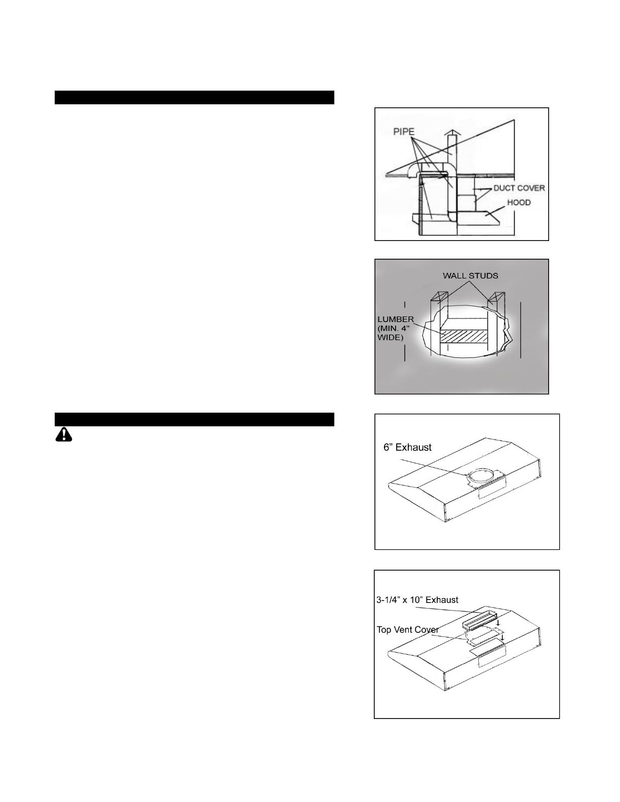
2. For 6” Round vent installation only:
- The 6” exhaust is already attached. Refer to
Figure 11. Align and secure the 6” Round
Plastic Collar {F} to two screws on hood. Follow
instructions in Step 5 to attach Hood Mounting
Bracket {P} and two Duct Cover Support {O}.
(Figure 15)
3. For Top 3-1/4” x 10” vent installation only:
- Remove attached 6” exhaust and discard.
(Figure 11) Keep 13 screws to install 3-14” x
10” exhaust & vent cover.
- Align Top Vent Cover {E} and 3-1/4” x 10”
Exhaust {D}. (Figure 12) Skip to Step 5 to attach
Hood-Mounting Bracket {P} and two Duct Cover
Support {O} using 14 screws (13 screws taken
from 6” exhaust. (Figure 15)
Figure 9
Figure 10
Figure 11
Figure 12


