Honeywell TH5110D User manual
- Category
- Thermostats
- Type
- User manual
This manual is also suitable for
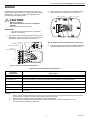
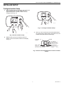
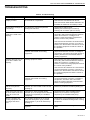
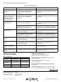
Honeywell TH5110D is a non-programmable thermostat that offers precise temperature control for various heating and cooling systems, including gas, oil, or electric heat with air conditioning, heat pumps, and more. It features manual or automatic changeover between heating and cooling modes, ensuring year-round comfort.
Honeywell TH5110D is a non-programmable thermostat that offers precise temperature control for various heating and cooling systems, including gas, oil, or electric heat with air conditioning, heat pumps, and more. It features manual or automatic changeover between heating and cooling modes, ensuring year-round comfort.


-
 1
1
-
 2
2
-
 3
3
-
 4
4
-
 5
5
-
 6
6
-
 7
7
-
 8
8
-
 9
9
-
 10
10
-
 11
11
-
 12
12


Honeywell TH5110D User manual
- Category
- Thermostats
- Type
- User manual
- This manual is also suitable for
Honeywell TH5110D is a non-programmable thermostat that offers precise temperature control for various heating and cooling systems, including gas, oil, or electric heat with air conditioning, heat pumps, and more. It features manual or automatic changeover between heating and cooling modes, ensuring year-round comfort.
Ask a question and I''ll find the answer in the document
Finding information in a document is now easier with AI
Related papers
-
Honeywell 5000 User manual
-
Honeywell T8011R User manual
-
-
-
-
-
-
-
-
Other documents
-
Bard 8403-058 User manual
-
Trane TCONT600AF11MA Installation Instructions Manual
-
-
-
ClimateMaster ATA11H01 Install Manual
-
-
-
-
-