Page is loading ...

FocusPRO
®
TH5320C
Non-Programmable Digital Communicating Thermostat
® U.S. Registered Trademark. Patents pending.
Copyright © 2008 Honeywell International Inc.
All rights reserved.
Installation
Guide
Must be installed by a trained, experienced technician
Read these instructions carefully. Failure to follow these instructions
can damage the product or cause a hazardous condition.
Need Help?
For assistance with this product please visit http://yourhome.honeywell.com
or call Honeywell Customer Care toll-free at 1-800-468-1502
69-2019EFS-02
To be used with up to 3 Heat 2 Cool conventional and heat pump systems with
W8835 Zone Panel or W8635 or THM5241 Equipment Interface Modules (EIM).
System Types
• Gas, oil, or electric heat with air
conditioning
• Warm air, hot water, high-
efficiency furnaces, heat pumps,
steam, gravity
• Heat only — two-wire systems,
three-wire zone valves (Series
20), and normally open zone
valves
• Heat only with fan
• Cool only
Use With
• W8835 Zone Panel—up to 3H/2C conventional or heat pump system
• W8635A EIM—up to 2H/2C conventional system
• W8635B EIM—up to 2H/1C heat pump system
• THM5421 EIM—up to 3H/2C conventional or heat pump

Installation Guide
69-2019EFS—02 2
Wallplate installation
1. Separate wallplate from thermostat.
2. Mount wallplate as shown below.
MERCURY NOTICE
If this product is replacing a control that contains mercury in a sealed tube, do not
place the old control in the trash. Contact your local waste management authority for
instructions regarding recycling and proper disposal.
M23800
Pull here to remove wallplate
from new thermostat.
CAUTION: ELECTRICAL HAZARD
Can cause electrical shock or equipment damage. Disconnect power before
beginning installation.
Thermostat Terminals (connect to network zone panel or EIM):
Wiring
Terminal designations
Thermostat mounting
Once wallplate is securely mounted on wall:
1. Push excess wire back into the wall opening.
2. Plug wall opening with non-flammable insulation.
3. Align the 4 tabs on the wallplate with the slots on the back of the thermostat.
4. Gently push the thermostat onto the wallplate; thermostat will snap into place.
Drill 3/16” holes for drywall. Drill 7/32” holes for plaster.
M23799
1
2
3
Wall anchors
Wallplate
Wire hole
Mounting screws
1 Data communication
2 Power
3 Common
This thermostat does not use batteries.
Installing batteries could lead to corrosion of
the batteries and damage the thermostat.

FocusPRO
®
TH5320
3 69-2019EFS—02
M23675
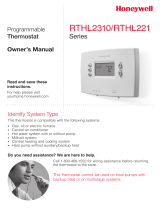
To begin, press and hold the s and FAN
buttons until the display changes.
Press s or t to change settings.
Press NEXT to advance to the next function.
Press DONE to exit and save settings.
Function
number
Setting
1
0
Done Next
Installer setup
Follow the procedure below to configure the thermostat to match the installed heating/cooling
system, and customize feature operation as desired.
Setup function Settings & options (factory default in bold)
0 Zone Instance 0 Not Zoned
1–9 Zoned (default setting 2)
1 System type 0 1 heat/1 cool conventional
1 1 heat/1 cool heat pump (no aux. heat)
2 Heat only — 2-wire systems, 3-wire zone valves (Series 20), and nor-
mally open zone valves
3 Heat only with fan
4 Cool only
5 2 heat/1 cool heat pump (with aux. heat)
6 2 heat/2 cool conventional
7 2 heat/1 cool conventional
8 1 heat/2 cool conventional
9 2 heat/2 cool heat pump (no aux. heat)
10 3 heat/2 cool heat pump (with aux. heat)
A Auto Discover
2 Changeover valve
(O/B terminal)
0 Changeover valve (O/B terminal energized in cooling)
1 Changeover valve (O/B terminal energized in heating)
3 Fan control
(heating)
0 Gas or oil furnace — equipment controls fan in heating
1 Electric furnace — thermostat controls fan in heating
5 Stage 1 heat cycle
rate (CPH: cycles/hour)
5 For gas or oil furnaces of less than 90% efficiency
1 For steam or gravity systems
3 For hot water systems & furnaces of over 90% efficiency
9 For electric furnaces
6 Second Stage Heat
Cycle Rate
5 Standard Gas or Oil Furnace
1 Steam or Gravity
3 90% + Efficient Furnace or Hot Water
9 Electric Furnace
[Other options: 2, 4, 6, 7, 8, 10, 11, 12 for Special Applications]
A Auto Discover
7 Third Stage Heat
Cycle Rate
5 Standard Gas or Oil Furnace
1 Steam or Gravity
3 90% + Efficient Furnace or Hot Water
9 Electric Furnace
[Other options: 2, 4, 6, 7, 8, 10, 11, 12 for Special Applications]
A Auto Discover
8 Emergency Heat
Cycle Rate
9 Electric Furnace
[Other options: 1–8, 10, 11, 12 for Special Applications]
A Auto Discover

Installation Guide
69-2019EFS—02 4
Installer system test
Setup function Settings & options (factory default in bold)
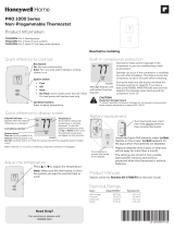
M23675
Press s / t to turn system on/off.
Press NEXT to advance to next test.
Press DONE to terminate system test.
Test number
10
System status
0
To begin, press and hold the s and t
buttons until the display changes
10 Heating system 0 Heat and fan turn off.
1 Stage 1 heat turns on. Fan turns on if Setup Function 1 is set to 1,
5, 9 or 10 OR Setup Function 3 is set to 1.
2 Stage 2 heat turns on.
3 Stage 3 heat turns on.
20 Emergency heating
system
0 Heat and fan turn off
1 Heat and fan turn on
30 Cooling system 0 Compressor and fan turn off
1 Compressor and fan turn on
2 Stage 2 compressor turns on
40 Fan system 0 Fan turns off
1 Fan turns on
9 Stage 1 compressor
cycle rate (CPH)
3 Recommended for most compressors
[Other cycle rate options: 1, 2, 4, 5 or 6 CPH]
10 Second Stage
Compressor
Cycle Rate
3 Compressor Cycle Rate
[Other options: 1, 2, 4, 5, 6 for Special Applications]
A Auto Discover
12 Manual/Auto
changeover
0 Manual changeover (Heat/Cool/Off)
1 Auto changeover (Heat/Cool/Auto/Off)
2 Auto changeover only (Auto)
14 Temperature
display
0 Fahrenheit
1 Celsius
15 Compressor
protection
5 Five-minute compressor off time
[Other options: 0, 1, 2, 3 or 4-minute off time]
19 Service Indicator 00–199 Diagnostic Codes
See Special function section on page 5.
23 Backlight Mode 0 Disabled
1 Enabled
26 Aux Control 0 Comfort
1 Economy
See Special function section on page 5.
27 Heat temperature
range stops
90 Max. heat temperature setting is 90 °F (32 °C)
[Other options: 40 °F to 89 °F (4.5 °C to 31.5 °C)]
28 Cool temperature
range stops
50 Min. cool temperature setting is 50 °F (10 °C)
[Other options: 51 °F to 99 °F (10.5 °C to 37 °C)]
System test System status

FocusPRO
®
TH5320
5 69-2019EFS—02
CAUTION: Compressor protection is bypassed during testing. To prevent equipment
damage, avoid cycling the compressor quickly
Special function
Auxiliary heat control (Setup Function 26):
• Comfort Setting: The thermostat will prioritize comfort over economy depending on heat
pump performance, load conditions and whether the thermostat is calling for the heat
pump. Raising the temperature just a few degrees will often activate the auxiliary heat.
• Economy Setting: The thermostat will attempt to reach the temperature setting
without activating the auxiliary heat. The thermostat will wait to activate the auxiliary
heat depending on heat pump performance, load conditions and how many degrees the
temperature setting is changed.
Diagnostic Codes (Setup Function 19):
When Error Codes are present the home screen of the thermostat will display “SERVICE NEEDED”
and scroll through all active error codes. Setup Function 19 will display a list of the 10 most recent
error codes, both active and inactive. The number on the right of the thermostat will show the
number of active and inactive error codes saved in the thermostat. To view the error codes press
the up arrow. To clear the list, press and hold both the up and down arrow keys. Active errors can
not be cleared; the source of the error must be resolved prior to clearing from the list.
Accessories & replacement parts
Please contact your distributor to order replacement parts.
Part Description Part Number
Small cover plate assembly* 50001137-001
Medium cover plate assembly* 50002883-001
12 pack of small cover plates* 50007297-001
12 pack of medium cover plates* 50007298-001
EnviraZONE Zone panel W8835A1004
Equipment Interface Module for 2H/2C conventional systems W8635A1006
Equipment Interface Module for 2H/2C heat pump systems W8635B1004
Telephone Access Module W8735B1003
2-Channel Telephone Access Module W8735D1009
4-Channel Telephone Access Module W8735D1017
*Use to cover marks left by old thermostats.
Temperature Ranges
• Heat: 40° to 90°F (4.5° to 32°C)
• Cool: 50° to 99°F (10° to 37°C)
Operating Ambient Temperature
• 32° to 120°F (0° to 48.9°C)
Shipping Temperature
• -20° to 120°F (-28.9° to 48.9°C)
Operating Relative Humidity
• 5% to 90% (non-condensing)
Physical Dimensions
TH5220D
• 3-9/16” H x 5-13/16” W x 1-1/2” D
91 mm H x 147 mm W x 38 mm D
TH5110D
• 3-7/16” H x 4-1/2” W x 1-5/16” D
86 mm H x 114 mm W x 33 mm D
Specifications
70 Thermostat information
(for reference only)
71 Software Revision Number (major revisions)
72 Software Revision Number (minor revisions)
73 Configuration Identification Number (major)
74 Configuration Identification Number (minor)
75 Production configuration date code (week)
76 Production configuration date code (year)
System test System status

® U.S. Registered Trademark.
© 2008 Honeywell International Inc.
69-2019EFS—02 M.S. Rev. 01-08
Honeywell International Inc.
1985 Douglas Drive North
Golden Valley, MN 55422
http://yourhome.honeywell.com
Automation and Control Solutions
Honeywell Limited-Honeywell Limitée
35 Dynamic Drive
Toronto, Ontario M1V 4Z9
Printed in U.S.A. on recycled
paper containing at least 10%
post-consumer paper fibers.
Honeywell International Inc
1985 Douglas Drive North
Golden Valley, MN 55422
http://yourhome.honeywell.com
Solutions d’automatisation et de contrôle
® Marque de commerce déposée aux É.-U.
© 2008 Honeywell International Inc.
Honeywell Limited-Honeywell Limitée
35, promenade Dynamic
Toronto (Ontario) M1V 4Z9
Honeywell International Inc.
1985 Douglas Drive North
Golden Valley, MN 55422
http://yourhome.honeywell.com
Soluciones para automatización y control
® Marca registrada de los EE. UU.
© 2008, Honeywell Internacional Inc.
Honeywell Limited-Honeywell Limitée
35 Dynamic Drive
Toronto, Ontario M1V4Z9
/