Page is loading ...

X-XX UL
INSTALLATION INSTRUCTIONS
Electronic
Heat Pump Thermostat
TAYSTAT 575
APPLICATION
The TAYSTAT 575 Electronic Heat Pump Thermostat provides electronic control of 24 Vac, two speed or two com-
pressor heat pump systems with auxiliary heat. The TAYSTAT 575 can be configured to operate a single compressor
heat pump system. Refer to Table 1 for a general description of the thermostat. All TAYSTAT 575 Thermostats require
a common wire to supply power.
Table 1. TAYSTAT 575 Thermostat Description.
MERCURY NOTICE
If this control is replacing a control that contains
mercury in a sealed tube, do not place your old
control in the trash. Dispose of properly.
Contact your local waste management authority for
instructions regarding recycling and the proper
disposal of the old control.
INSTALLATION
When Installing this Product...
1. Read these instructions carefully. Failure to follow
the instructions can damage the product or cause a
hazardous condition.
2. Check the ratings given in the instructions and on
the product to make sure the product is suitable for
your application.
3. Installer must be a trained, experienced service
technician.
4. After completing installation, use these instructions
to check out the product operation.
CAUTION
Electrical Shock or Equipment Damage Hazard.
Can shock individuals or short
equipment circuitry.
Disconnect power supply before installation.
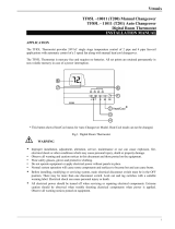
Location
Install the thermostat about 5 ft (1.5m) above the floor in
an area with good air circulation at average temperature.
See Fig. 1.
Do not install the thermostat where it can be affected by:
— drafts, or dead spots behind doors and in corners.
— hot or cold air from ducts.
— radiant heat from sun or appliances.
— concealed pipes and chimneys.
— unheated (uncooled) areas such as an outside wall
behind the thermostat.
®U.S. Registered Trademark. • • All Rights Reserved
Pub. No. 11-HD28D2-1
69-1591-1
TAYSTAT Changeover
System Selection
Fan
Selection Comments
575 Automatic Em. Ht. – Heat-Off-Auto-Cool On-Auto Down-selectalbe for single compressor
systems.

69-1591–1
2
ELECTRONIC HEAT PUMP THERMOSTAT
Pub. No. 11-HD28D2-1
Fig. 1. Typical location of thermostat.
5 FEET
[1.5 METERS]
YES
NO
NO
NO
M10106
Fig. 2. Mounting the wallplate.
WIRES
THROUGH WALL
WALL
MOUNTING
HOLES
MOUNTING
SCREWS
M6530
WALL
ANCHORS
(2)
Wallplate Installation
Mount tthermostat horizontally on the wall or on a 2 in. x 4
in. wiring box.
1. Position and level the wallplate (for appearance
only). The thermostat functions properly even when
not level.
2. Use a pencil to mark the mounting holes. See
Fig. 2.
3. Remove the wallplate from the wall and drill two
3/16 inch holes in the wall (if drywall) as marked. For
firmer material such as plaster or wood, drill two
7/32 inch holes. Gently tap anchors (provided) into
the drilled holes until flush with the wall.
4. Position the wallplate over the holes, pulling wires
through the wiring opening.
5. Loosely insert the mounting screws into the holes.
6. Tighten mounting screws.

69-1591–1
3
ELECTRONIC HEAT PUMP THERMOSTAT
Pub. No. 11-HD28D2-1
Fig. 4. Correct wiring technique.
Mounting Thermostat
1. Engage tabs at the top of the thermostat and
wallplate. See Fig. 5.
2. Press lower edge of case to close and latch.
M4826
FOR WRAPAROUND
INSERTION STRIP
7/16 IN. (11 MM).
FOR STRAIGHT
INSERTION STRIP
5/16 IN. (8 MM).
WIRING
All wiring must comply with local electrical codes and
ordinances. Refer to Fig. 3 for typical hookup. A letter code
is located near each terminal for identification.
COMPRESSOR
CONTACTOR 2
M20273A
W
L1
L2
FAN
SWITCHOVER
VALVE
Y1 Y2
X2
THERMOSTAT
B RO
COMPRESSOR
CONTACTOR 1
EM. HT.
RELAY
TRANSFORMER
OT OT
OUTDOOR
TEMPERATURE
SENSOR
TAYSENS100A
G
F
DEFROST
CONTROLLER
1
1
2
POWER SUPPLY. PROVIDE DISCONNECT MEANS AND OVERLOAD
PROTECTION AS REQUIRED.
2
FEATURE NOT AVAILABLE ON ALL SYSTEMS.
3
USE OUTDOOR TEMPERATURE SENSOR TAYSENS200A AND CONFIGURE
INSTALLER SETUP NUMBERS 24 TO 1.
3
AUX.
HEAT
RELAY
BLUE
YELLOW
BROWN
GREEN
ORANGE
BLACK
WHITE
RED
Fig. 3. Typical hookup in heat pump system with emergency heat relay.
CAUTION
Electrical Shock or Equipment Damage Hazard.
Can shock individuals or short equipment
circuitry.
Disconnect power supply before installation.
1. Loosen the terminal screws on the wallplate and
connect the system wires. See Fig. 4.
IMPORTANT
Use 18 gauge, color-coded thermostat cable for
proper wiring.
2. Securely tighten each terminal screw.
3. Push excess wire back into the hole.
4. Plug the hole with nonflammable insulation to
prevent drafts from affecting the thermostat.
Fig. 5. Mounting thermostat on wallplate.
NOTE: To remove the thermostat from the wall, first
pull out at the bottom of the thermostat; then
remove top.
M6798
A
B.
PRESS LOWER EDGE OF CASE TO LATCH.
A.
ENGAGE TABS AT TOP OF THERMOSTAT AND WALLPLATE
.

69-1591–1
4
ELECTRONIC HEAT PUMP THERMOSTAT
Pub. No. 11-HD28D2-1
Using Thermostat Keys
Use thermostat keys to:
• Set temperature,
• Display present setting,
• Configure Installer Setup,
• Check System-Test,
• Display outdoor temperature (select models).
• Set system operation,
• Set fan operation.
See Fig. 6 for the key information.
Fig. 7. ASYSTAT 575 (automatic changeover)
System and Fan key locations.
NOTE: Always press the system and fan keys with your
fingertip or similar blunt tool. Sharp instruments
like a pen or pencil point can damage the
keyboard.
Emergency Heat
The Emergency Heat feature allows you to turn on the
electric heat section of the system by moving the
System switch to the Em. Ht. position. The LED lights
(see Fig. 7) when the thermostat is moved to the
Em. Ht. position or when the system goes into defrost.
The thermosat displays Em. Ht. when the system calls
for emergency heat.
LED indication
One LED indicator is located on the lower right bottom
of the thermostat. It indicates when a CHECK signal is
sent to the thermostat from the system. See Fig. 7.
Temperature Settings
The default setpoint for heat is 70°F (21°C) and for cool is
78°F (25.5°C). Press the increase ▲ or decrease ▼ key to
change the present setting. To change between heat and
cool, press the Information i key until the setting to be
changed appears.
Cooling Droop
Cooling system operation or cycling below the setpoint
temperature is called “Cooling Droop”. Thermostats that
provide this operation improve the comfort during
extended off periods by providing air circulation to
prevent stagnation and improved moisture removal due
to increased run time. Cooling Droop is most effective in
mild weather conditions and during nighttime operation
(low load). The effect of Cooling Droop on indoor
temperature operation typically lowers the indoor
temperature by up to one or two degrees. If the cooling
droop is not desired, it can be disabled.
Comfort R™
Comfort R helps achieve comfort with a lower humidity
level. When enabled (selected in installer setup) the
thermostat calculates a fan delay on a call for cool. The
calculated delay maximizes dehumidification and
comfort from the air conditioning system.
M10147C
i
Press to select
heating or cooling
equipment.
Em. Ht.
-Emergency heating
Heat— Heating equipment
Off — No equipment
Cool—Cooling equipment
Auto—Thermostat
automatically selects
heating and cooling
equipment.
Press to select
heating or cooling
equipment.
On— Fan runs continuously
Auto—Fan runs when
heating or cooling
equipment operates
System
System
System
Fan
Fan
Fan
TWO LED INDICATORS ON MOST MODELS.
1
1
M680
1
DISPLAY PRESENT
SETTINGS AND SCROLL
THROUGH INSTALLER
SETUP MODES
(INFORMATION KEY)
i
DECREASE
TEMPERATURE
SETTING
INCREASE
TEMPERATURE
SETTING
Fig. 6. Thermostat key locations and descriptions.
SETTINGS
System and Fan Settings
System settings control the thermostat operation as
follows:
Em. Heat: The thermostat cycles the Emergency Heat
relay and the highest heat stage. The cooling
system is off. The compressor is de-energized.
Heat: The thermostat controls the heating.
Off: Both the heating and cooling are off.
Cool: The thermostat controls the cooling.
Auto: The thermostat automatically changes between
heating and cooling operation, depending on the
indoor temperature.
Fan settings control the system fan as follows:
On: Fan operates continuously.
Auto: Equipment controls fan.
The system default setting is Heat and the fan default
setting is Auto. Use the keyboard to change to the desired
settings. See Fig. 7.

69-1591–1
5
ELECTRONIC HEAT PUMP THERMOSTAT
Pub. No. 11-HD28D2-1
INSTALLER SETUP
NOTE: For most applications, the thermostat factory
settings do not need changing. Review the
Factory Setting column in Table 2 and if no
changes are necessary, go to the Installer
System-Test section.
Use the Installer Setup to customize the thermostat to
specific systems. Some of the options include temperature
display, changeover, minimum equipment on time and
minimum off time. Installer Setup numbers are listed in
Table 2. It includes all the configuration options and the
factory-settings available for the TAYSTAT 575.
IMPORTANT
The Installer Setup must be set correctly for the
HVAC equipment, thermostat and subbase to
operate properly.
A combination of key presses are required to use the
Installer Setup feature:
1. To enter the Installer Setup, press and hold the
Information i key and the increase ▲ and
decrease ▼ keys until the first number displays. All
display segments appear for approximately three
seconds before the number displays. See Fig. 8
and 9.
2. To advance to the next Installer Setup, press the
Information i key.
3. To change a setting, press the increase ▲ or
decrease ▼ key.
4. To exit the Installer Setup, press and hold the
Information i key until the display returns to
normal (approximately three seconds). The display
scrolls the numbers backward to get to the normal
display. The Installer Setup is automatically exited if
no key presses are made for five minutes.
Fig. 8. Display of all LCD segments.
Fig. 9. Display of installer setup and setting.
NOTE: Only configurable numbers are shown.
Em HeatOffCool Auto Only
Heat Cool
OnAuto
System Fan
Room
Outdoor
Em Ht Temporary Setting
Wait
%Humid
Aux Ht
Remote
Repl
Batt
M4844
Table 2. Thermostat Installer Setup Options.
M10105A
INSTALLER SETUP
NUMBER DISPLAY
(COLUMN 2 OF TABLE 2)
FACTORY SETTING OR
OTHER CHOICE DISPLAY
(COLUMN 3 OR 5 OF TABLE
2)
Installer
Setup Number
Factory-Setting
Other Choices
(Press ▲ or ▼ key to change)
Select Display Description Display Description
Number of compressor
stages
03 01 2 heating staes and 1
cooling stage (2H/1C)
02 3 heating stages and 2
cooling stages (3H/2C)
Compressor 1 heating
cycle rate
04 03 3—3 cph recommended
5, 6 or 9 cph—not
recommended
05, 06
or 09
05—5 cph
06—6 cph
09—9 cph
Compressor 2 heating
cycle rate
05 03 3—3 cph recommended
5, 6 or 9 cph—not
recommended
Auxiliary heating cycle
rate
06 05 5—5 cph recommended
3, 6 or 9 cph—not
recommended
03, 06,
or 09
03—3 cph
06—6 cph
09—9 cph
Em. Ht. cycle rate 07 05 5—5 cph recommended
3, 6 or 9 cph—not
recommended
Stage 1 cooling cycle rate 09 03 3—3 cph recommended
2 or 5 cph—not
recommended
02 or
05
02—2 cph
05—5 cph
Stage 2 cooling cycle rate 10 03
System setting
adjustment
12 00 Automatic changeover 01 01—Manual changeover
02—Auto Only

69-1591–1
6
ELECTRONIC HEAT PUMP THERMOSTAT
Pub. No. 11-HD28D2-1
Table 2. Thermostat Installer Setup Options (Continued).
Installer
Setup Number
Factory-Setting
Other Choices
(Press ▲ or ▼ key to change)
Select Display Description Display Description
Degree temperature
display
14 00 Temperature displays in
°F
01 Temperature displays in °C
Extended fan operation in
heating
19 00 No extended fan
operation after the call
for heat ends
01, 02
or 03
01—Fan operation exends
30 seconds after the call
ends
02—Fan operation exends
60 seconds after the call
ends
03—Fan operation exends
90 seconds after the call
ends
Extended fan operation in
cooling
20 00 No extended fan
operation after the call
for cool ends
01, 02
or 03
01—Fan operation exends
30 seconds after the call
ends
02—Fan operation exends
60 seconds after the call
ends
03—Fan operation exends
90 seconds after the call
ends
Outdoor temperature
display (select models)
24 00 No outdoor temperature
displays.
01 Outdoor temperature is
displayed. Needs a
TAYSENS100A Outdoor
Sensor
Comfort-R Enable 28 00 No fan delay 01 or
02
01—30 seconds (maximum
delay)
02—15 seconds (maximum
delay)
Minimum deadband
between heating and
cooling in auto
changeover mode
30 04 Heating and cooling
setpoints can be set no
closer than 4°F (2°C)
03 thru
10
Heating and cooling
setpoints can be set no
closer than the chosen
value:
3—3°F (1.5°C)
4—4°F (2°C)
5—5°F (2.5°C)
6—6°F (3°C)
7—7°F (3.5°C)
8—8°F (4°C)
9—9°F (4.5°C)
10—10°F (5°C)
Minimum on time (heat) 32 10 Ten-minute minimum on
time for compressor
(heating)
00 thru
15
Minimum number of minutes
(0 thru 15) the compressor is
on during call for heat
Minimum on time
(cooling)
33 10 Ten-minute minimum on
time for compressor
(cooling)
00 thru
15
Minimum number of minutes
(0 thru 15) the compressor is
on during call for cool
Temperature range stops
in heating
34 85 Highest heating
sepoint setting
01 Temperature range (1°F
increments) of heating
setpoint setting
Temperature range stops
in cooling
35 65 Lowest cooling
sepoint setting
— Temperature range (1°F
increments) of cooling
setpoint setting

69-1591–1
7
ELECTRONIC HEAT PUMP THERMOSTAT
Pub. No. 11-HD28D2-1
Em HeatOffCool Auto Only
Heat Cool
OnAuto
System Fan
Room
Outdoor
Em Ht Temporary Setting
Wait
%Humid
Aux Ht
Remote
Repl
Batt
M4844
INSTALLER SYSTEM-TEST
Use the Installer System-Test to check the thermostat
configurations and operation. Refer to Table 3 for a list of
the available system-tests.
To start the system-test:
CAUTION
Equipment Damage Hazard.
Minimum compressor off-time is bypassed
during the Installer System Test.
Be aware that equipment damage can occur if the
compressor is cycled too quickly.
Press and hold the increase ▲ and decrease ▼ keys, at
the same time, until two zeros appear. All segments of the
LCD are displayed before the zeros appear.
NOTE: Press and hold the increase ▲ and decrease ▼
keys for three seconds to exit the system-test.
The system-test times out after five minutes
without any key presses.
Table 3. Installer System-Tests.
Refer to Table 4 for descriptions of the specific tests.
M6792
TEST NUMBER
Test
Number System-Test Description
10-19 Heating equipment can be turned on and off
20-29 Emergency heat (select models) equipment
can be turned on and off
30-39 Cooling equipment can be turned on and off
40-49 Fan equipment can be turned on and off
60-69 System key or system switch position test
70-79 Thermostat information displayed including
date code and software versions.
Table 2. Thermostat Installer Setup Options (Continued).
Installer
Setup Number
Factory-Setting
Other Choices
(Press ▲ or ▼ key to change)
Select Display Description Display Description
Temperature display
adjusment
37 00 No difference in
displayed temperature
and actual room
temperature.
3, 2, 1,
-1, -2,
or -3
3—Display adjusts to 3°F
higher than actual room
temperature.
2—Display adjusts to 2°F
higher than actual room
temperature.
1—Display adjusts to 1°F
higher than actual room
temperature.
-1—Display adjusts to 1°F
lower than actual room
temperature.
-2—Display adjusts to 2°F
lower than actual room
temperature.
-3—Display adjusts to 3°F
lower than actual room
temperature.
Minimum off time (heat) 38 05 Five minute minimum off
time for the heating.
00 thru
15
Minimum number of minutes
(0 thru 15) the compressor is
off between calls for heat.
Minimum off time
(cooling)
39 05 Five minute minimum off
time for the heating.
00 thru
15
Minimum number of minutes
(0 thru 15) the compressor is
off between calls for heat.
Cooling Droop 41 01 Cooling droop activated 00 No cooling droop

69-1591–1
8
ELECTRONIC HEAT PUMP THERMOSTAT
Pub. No. 11-HD28D2-1
Table 4. Installer System-Test Options.
Key to
Press
Test
Number Description
Heating Equipment System Test
i
10 Enter heating equipment system test.
▲ 11 Stage-one heat comes on. The system fan is also energized.
a
▲ 12 Stage-two heat comes on. Stage-one heat and system fan remain on.
▲ 13 Stage-three heat comes on. Stage-one heat and stage two remain on.
▼ 12 Stage-three heat turns off.
▼ 11 Stage-two heat turns off.
▼ 10 Stage-one heat and system fan turn off.
Emergency Heating Equipment System-Test
i 20 Change from heating to emergency heating equipment system-test.
▲ 21 Emergency heat comes on. System fan also comes on.
▼ 20 Emergency heat turns off.
Cooling Equipment System Test
i
30 Enter cooling equipment system test.
▲ 31 Stage-one cool and system fan come on.
▲ 32 Stage-two cool comes on. Stage-one cool and system fan remain on.
▼ 31 Stage-two cool turns off.
▼ 30 Stage-one cool and system fan turn off.
Fan Equipment System Test
i
40 Change from cooling to fan equipment system test.
▲ 41 Fan comes on.
▼ 40 Fan turns off.
Key Operation System Test
IMPORTANT
Test Numbers will be displayed only when the system is configured for the selected function.
EXAMPLE: Numbers 60, 61 and 62 are the only numbers that will be displayed when a system
is configured for heat only.
SYSTEM KEY
i
60 Change from cooling or fan to key operation system test.
System 61 Heat Test Number is displayed.
System 62 Off Test Number is displayed.
System 63 Cool Test Number is displayed.
System 64 Auto Test Number is displayed.
System 65 Emergency Heat Test number is displayed.
NOTE: Press system key again to repeat the System Key System-Test.
FAN KEY SYSTEM TEST
Fan 68 Fan On Test Number is displayed.
Fan 69 Fan Off Test Number is displayed.

69-1591–1
9
ELECTRONIC HEAT PUMP THERMOSTAT
Pub. No. 11-HD28D2-1
M4867
5. Press the increase ▲ key again to display the
EEPROM identification code (Example: 222 =
EEPROM ID 222).
6. Press and hold the increase ▲ and decrease ▼
keys until the room temperature is displayed to exit
the system-test. The system-test times out after five
minutes without any key presses.
CHECKOUT
Outdoor Temperature Sensor
(Where Applicable)
Allow the outdoor temperature sensor to absorb the
outdoor air for a minimum of five minutes before taking a
reading. With an accurate thermometer (±1°F [±0.5°C]),
measure the temperature at the sensor location, allowing
time for the thermometer to stabilize before reading. Match
the thermometer reading to the outdoor temperature
display at the thermostat.
M6791
M4864
M4865
M4866
Thermostat Information
1. Press the Information i key to access the thermo-
stat information.
2. Press the increase ▲ key to display the production
date code. The first two large digits are the month
and the third digit is the last digit of the year
(Example: 026 = February 1996).
3. Press the increase ▲ key again to display the
software identification code (Example: 02 =
software ID code 2).
4. Press the increase ▲ key again to display the
software revision number (Example: 001 =
revision number 1).

69-1591–1
10
ELECTRONIC HEAT PUMP THERMOSTAT
Pub. No. 11-HD28D2-1
TROUBLESHOOTING GUIDE
a
Available on select models.
Symptom Possible Cause Action
Display does not
come on.
Thermostat is not being
powered.
• Check that B terminal is connected to the system
transformer.
• Check for 24 Vac between B and R terminals.
— If missing 24 Vac:
— Check if the circuit breaker is tripped—reset the
circuit breaker.
— Check if the system fuse is blown—replace the fuse.
— Check if the power switch on the HVAC equipment is
in the Off position—set to the On position.
— Check wiring between thermostat and HVAC
equipment—replace any broken wires and tighten
any loose connections.
— If 24 Vac is present, proceed with troubleshooting.
Thermostat microprocessor is
locked up.
Remove the thermostat from wallplate for 2 minutes. After 2
minutes, replace the thermostat on the wallplate.
Temperature
display is incorrect.
Room temperature display was
reconfigured.
Enter Installer Setup Number 37 and reconfigure the display.
Thermostat is configured for °F
or °C display.
a
Enter Installer Setup Number 14 and reconfigure the display.
Bad thermostat location. Relocate the thermostat.
Temperature
settings will not
change. (Example:
Cannot set the
The upper or lower temperature
limits were reached.
Check the temperature setpoints:
• Heating limits are 55 to 85°F (13 to 29°C)
• Cooling limits are 65 to 99°F (18 to 37°C).
heating higher or
the cooling lower.)
The setpoint temperature range
stops were configured.
Check Installer Setup mode numbers 34 and 35 and
reconfigure the setpoint stops.
Heating does not
come on.
No power to the thermostat. • Check that B terminal is connected to the system
transformer.
• Check for 24 Vac between B and R terminals.
— If missing 24 Vac:
— Check if the circuit breaker is tripped—reset the
circuit breaker.
— Check if the system fuse is blown—replace the fuse.
— Check if the system switch at the equipment is in the
Off position—set to the On position.
— Check wiring between thermostat and HVAC
equipment—replace any broken wires and tighten
any loose connections.
— If 24 Vac is present, proceed with troubleshooting.
Thermostat minimum off time is
activated.
Wait up to five minutes for the system to respond.
System selection is not set to
Heat.
Set system selection to Heat.
Heating setpoint is below room
temperature.
Check heating setpoint. Set heating setpoint to desired
temperature.

69-1591–1
11
ELECTRONIC HEAT PUMP THERMOSTAT
Pub. No. 11-HD28D2-1
Troubleshooting Guide (Continued)
a
Available on select models.
Symptom Possible Cause Action
Cooling does not
come on.
No power to the thermostat. • Check that B terminal is connected to the system
transformer.
• Check for 24 Vac between B and R and Y terminals.
— If missing 24 Vac:
— Check if the circuit breaker is tripped—reset the
circuit breaker.
— Check if the system fuse is blown—replace the fuse.
— Check if the system switch at the equipment is in the
Off position—set to the On position.
— Check wiring between thermostat and HVAC
equipment—replace any broken wires and tighten
any loose connections.
— If 24 Vac is present, proceed with troubleshooting.
Thermostat minimum off time is
activated.
• Wait up to five minutes for the system to respond.
• Enter Installer Setup mode number 33. Reconfigure
minimum off time (if required).
System selection is not set to
Cool.
Set system selection to Cool.
System On
indicator is lit, but
no heat is being
delivered.
Heating equipment is not
operating.
Verify operation of heating equipment in system test.
Outdoor
temperature
not displayed
a
.
Option not activated. Enter Installer Setup mode number 24 and set to 01.
Thermostat must have OT terminals and a TAYSENS100A
installed.
Outdoor
temperature
Outdoor sensor is connected
incorrectly.
Refer to TAYSENS100A installation instructions and check
wiring between the thermostat and sensor.
display is
incorrect
a
.
Incorrect sensor. Replace sensor with TAYSENS100A Sensor.

69-1591–1 4-02
American Standard Inc.
Troup Highway
Tyler, TX 75711-9010
CUSTOMER ASSISTANCE
If, after reading this guide, you have any questions concerning the operation of your thermostat, please call the Thermostat
Customer Assistance Helpline at 1-877-880-3381.
For service, contact your local heating and cooling contractor.
Pub. No. 11-HD28D2-1
/