Page is loading ...

1
Owner’s Manual
NetDirector
™
32-Port
8-User Matrix KVM Switch
Model: B060-032-8
1111 W. 35th Street, Chicago, IL 60609 USA
(773) 869-1234 • www.tripplite.com
Copyright © 2008 Tripp Lite. All rights reserved. All trademarks are the property of their respective owners.
WARRANTY
REGISTRATION:
register online today for a
chance to win a FREE Tripp Lite
product—www.tripplite.com/warranty

2
Table of Contents
1. Introduction . . . . . . . . . . . . . . . . . . . . . . . . . . . . . . . . . . . Page 2
2. Important Safety Instructions . . . . . . . . . . . . . . . . . . . . . . . . . 3
3. System Components . . . . . . . . . . . . . . . . . . . . . . . . . . . . . . . . 4
4. Compatibility & Required Hardware . . . . . . . . . . . . . . . . . . . . 4
4.1 Compatibility . . . . . . . . . . . . . . . . . . . . . . . . . . . . . . . . . . . . 4
4.2 Required Hardware . . . . . . . . . . . . . . . . . . . . . . . . . . . . . . . 4
5. Features . . . . . . . . . . . . . . . . . . . . . . . . . . . . . . . . . . . . . . . . . . . 5
6. Rackmounting . . . . . . . . . . . . . . . . . . . . . . . . . . . . . . . . . . . . . . 6
7. Single-Level Installation. . . . . . . . . . . . . . . . . . . . . . . . . . . . . . 7
8. Multilevel Installation . . . . . . . . . . . . . . . . . . . . . . . . . . . . . . . . 8
8.1 Cascading . . . . . . . . . . . . . . . . . . . . . . . . . . . . . . . . . . . . 8
8.2 Daisy-Chaining . . . . . . . . . . . . . . . . . . . . . . . . . . . . . . . 11
9. Basic Operation . . . . . . . . . . . . . . . . . . . . . . . . . . . . . . . . . . . 12
10. Administrator Utility . . . . . . . . . . . . . . . . . . . . . . . . . . . . . . . 12
10.1 Network Installation . . . . . . . . . . . . . . . . . . . . . . . . . . . 12
10.2 Topology Considerations . . . . . . . . . . . . . . . . . . . . . . 13
10.3 Setting the IP Address . . . . . . . . . . . . . . . . . . . . . . . . . 13
10.4 Logging In . . . . . . . . . . . . . . . . . . . . . . . . . . . . . . . . . . . 14
10.5 Menus & Icons . . . . . . . . . . . . . . . . . . . . . . . . . . . . . . . 16
10.6 Port Status . . . . . . . . . . . . . . . . . . . . . . . . . . . . . . . . . . 17
10.7 Naming Stations . . . . . . . . . . . . . . . . . . . . . . . . . . . . . . 17
10.8 Setting the Web Page Session Timeout . . . . . . . . . . . 18
10.9 Network Confi guration. . . . . . . . . . . . . . . . . . . . . . . . . 18
10.10 IP Installer Setting . . . . . . . . . . . . . . . . . . . . . . . . . . . . 19
10.11 Setting Date & Time . . . . . . . . . . . . . . . . . . . . . . . . . . . 20
10.12 Group Management . . . . . . . . . . . . . . . . . . . . . . . . . . . 20
10.13 User Management. . . . . . . . . . . . . . . . . . . . . . . . . . . . . 22
10.14 Port Management . . . . . . . . . . . . . . . . . . . . . . . . . . . . . 25
10.15 Setting the OSD View . . . . . . . . . . . . . . . . . . . . . . . . . . 27
10.16 Searching for Ports & Stations . . . . . . . . . . . . . . . . . . 30
10.17 Upgrading Firmware. . . . . . . . . . . . . . . . . . . . . . . . . . . 30
10.18 Replacing the Root B060-032-8. . . . . . . . . . . . . . . . . . 33
10.19 Backing Up & Restoring Settings . . . . . . . . . . . . . . . . 34
10.20 Viewing & Ending User Sessions . . . . . . . . . . . . . . . . 34
10.21 Viewing System Information & Help . . . . . . . . . . . . . . 36
10.22 Logging Out . . . . . . . . . . . . . . . . . . . . . . . . . . . . . . . . . 36
11. OSD Operation . . . . . . . . . . . . . . . . . . . . . . . . . . . . . . . . . . . 36
11.1 OSD Main Screen . . . . . . . . . . . . . . . . . . . . . . . . . . . . . 36
11.2 OSD Navigation . . . . . . . . . . . . . . . . . . . . . . . . . . . . . . 37
11.3 Accessing Switches & Computers . . . . . . . . . . . . . . . 38
11.4 OSD Functions . . . . . . . . . . . . . . . . . . . . . . . . . . . . . . . 39
11.5 Management Menus . . . . . . . . . . . . . . . . . . . . . . . . . . . 41
12. Hotkey Mode . . . . . . . . . . . . . . . . . . . . . . . . . . . . . . . . . . . . . 44
12.1 Invoking Hotkey Mode . . . . . . . . . . . . . . . . . . . . . . . . . 45
12.2 Hotkey Port Switching . . . . . . . . . . . . . . . . . . . . . . . . . 45
12.3 Hotkey Beeper Control. . . . . . . . . . . . . . . . . . . . . . . . . 46
12.4 Keyboard Emulation. . . . . . . . . . . . . . . . . . . . . . . . . . . 46
13. Troubleshooting . . . . . . . . . . . . . . . . . . . . . . . . . . . . . . . . . . 47
14. Specifi cations . . . . . . . . . . . . . . . . . . . . . . . . . . . . . . . . . . . . 48
15. Storage & Service . . . . . . . . . . . . . . . . . . . . . . . . . . . . . . . . . 49
16. Warranty & Warranty Registration. . . . . . . . . . . . . . . . . . . . 49
1. Introduction
Tripp Lite’s NetDirector™ Matrix KVM Switch (Model B060-032-8) enables eight consoles to independently and simultaneously control up to 32 directly
connected computers. The installation can be expanded to over 8000 computers/servers via a combination of daisy chaining and cascading. Premium
features include:
• Eight consoles independently and simultaneously control up to 32 directly connected computers, and hundreds of computers/servers connected via
cascaded B060-032-8 KVM switches
• Cascade up to 3 levels of B060-032-8 and 1 level of B007-008 KVM switches to support over 8,000 computers/servers
• Back up and restore settings when changing root stations
• Web-based B060-032-8 Administrator Utility simplifi es confi guration and maintenance of the KVM installation
• Three levels of user access control (Super Administrator, Administrator, and User)

3
1. Introduction
• Super Administrators can view and end sessions of other users
• Super Administrators can broadcast keyboard input to all computers in the KVM installation
• Supports password authentication
• Additional user port on front panel for easy system maintenance
• Hot pluggable—add or remove components without having to power off the KVM switch
• Multiplatform support—PC, Mac and serial
• Multi-architecture compatibility—PC (x86/x64), Macintosh PowerPC
• Supports up to 1024 user accounts and up to 256 group accounts
• Automatic video routing technology enables multiple consoles to access separate ports in cascaded/daisy-chained KVM Switches at the same time
• Convenient computer selection via intuitive hotkey combinations or On Screen Display (OSD) menus
• Auto-sensing of station’s position on daisy-chain installations; OSD and front panel LED indicates station’s position
• Port names are automatically reconfi gured when the station sequence is changed
• Auto Scan feature for monitoring user-selected computers
• PS/2 keyboard and mouse emulation—computers boot even when the KVM console focus is elsewhere
• LCD, VGA, SVGA, XGA, and MultiSync support; DDC2B
• Superior video quality – 1024 x 768 @ 60Hz for up to 300 m; 1920 x 1440 @ 60Hz (distance depends on installation environment)
• Auto Signal Compensation (ASC) assures optimum video resolution for distances up to 300 m between computers and KVM consoles—no DIP switch
setting required
2. Important Safety Instructions
SAVE THESE INSTRUCTIONS
This manual contains instructions and warnings that should be followed during the installation and operation of this product. Failure to comply may
invalidate the warranty and cause property damage and/or personal injury.
Installation Warnings
• Install the KVM switch in a controlled indoor environment, away from moisture, temperature extremes, fl ammable liquids and gasses, conductive
contaminants, dust and direct sunlight.
• Operate the KVM switch at indoor temperatures between 32° F and 104° F (0° C and 40° C).
• When connecting the KVM switch to the facility’s power supply circuit, ensure that the circuit is not overloaded.
Rackmount Warnings
• Ensure there is adequate airfl ow within the rack.
• Mount the KVM switch evenly within the rack to eliminate potentially hazardous uneven mechanical loading conditions.
• Ensure that all rackmount equipment is reliably grounded.
Connection Warnings
• Use of this equipment in life support applications where failure of this equipment can reasonably be expected to cause the failure of the life support
equipment or to signifi cantly affect its safety or effectiveness is not recommended. Do not use this equipment in the presence of a fl ammable anesthetic
mixture with air, oxygen or nitrous oxide.
• Ensure that the cables used with the KVM switch are not close to any sources of electrical noise interference such as fl uorescent lights, HVAC systems or
motors.
• Ensure that the distance between any computer and the KVM switch does not exceed 33 ft. (10m).
• Shut down all PS/2 computers before connecting the keyboard, monitor and mouse to ensure that they will be recognized by the computer.
Maintenance Warnings
• The KVM switch does not require routine maintenance. There are no user-serviceable parts inside. Only authorized service personnel should open the
case for any reason. Disconnect the unit from AC input power before servicing.

4
3. System Components
4. Compatibility & Required Hardware
The NetDirector Matrix KVM Switch consists of:
• B060-032-8 Matrix KVM Switch
• 1 Power Cord
• 1 Rackmount Kit
• 1 Set of Foot Pads
4.1 Compatibility
4.2 Required Hardware
For KVM Consoles
The following hardware components are required for each KVM console:
• A VGA, SVGA, or MultiSync monitor capable of displaying the highest resolution provided by any computer in the installation
• Keyboard and mouse (PS/2 or USB)
For Connected Computers/Servers
The following hardware components are required for each computer:
• An HD15 VGA port
• PS/2 mouse and keyboard ports (MiniDIN6) or one USB port
Required Cables & Interface Units
Console Interface Units (CIUs) are required to connect consoles to the B060-032-8. Server Interface Units (SIUs) are required to connect multiplatform
computers and certain cascaded KVM switches to the B060-032-8. The following table lists the Console Interface Units (CIUs), Server Interface Units
(SIUs) and cables available for the B060-032-8.
Function CIU, SIU or Cable Required
Connecting a PS/2 KVM Console to a B060-032-8 B062-002-PS2 Console Interface Unit
Connecting a USB KVM Console to a B060-032-8 B062-002-USB Console Interface Unit
Connecting B060-032-8 to a PS/2 Server B054-001-PS2 Server Interface Unit
Connecting B060-032-8 to a USB Server B054-001-USB Server Interface Unit
Connecting CIUs and SIUs to B060-032-8, or cascading to Cat5 Cable (Tripp Lite N001-, N002- and N105 Series Cat5 Cables)
another B060-032-8
Daisy-Chaining to a B060-032 or B060-016-2 Daisy-Chain Cable included with B060-032 and B060-016-2.
Use Tripp Lite P770-Series Daisy-Chain cables for longer cable lengths.
Operating System Version Supported
Windows 2000 and higher
Linux RedHat 6.0 and higher
Linux SuSE 8.2 and higher
Linux Mandriva (Mandrake) 9.0 and higher
UNIX AIX 4.3 and higher
UNIX FreeBSD 3.51 and higher
UNIX Sun Solaris 8 and higher
Novell Netware 5.0 and higher
Mac OS 9 and higher
OS/2 Warp Ver. 2
DOS 6.22

5
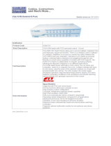
5. Features
B060-032-8 Front View
B060-032-8 Rear View
Power LED: Lights (blue) to indicate that the unit is receiving power.
Server Port LEDs:
Port LED Status
Steady Amber Light KVM Port is selected and the connected computer is powered on
Flashing Amber Light KVM Port is selected and is cascaded to a powered on KVM Switch
Steady Green Light KVM Port is not selected and the connected computer is powered on
Flashing Green Light KVM Port is not selected and is cascaded to a powered on KVM Switch
Steady Red Light KVM Port is selected and the connected computer is powered off
No Light KVM Port is not selected and the connected computer is powered off; or there is no computer connected to the KVM Port
User Port LEDs:
• Illuminates (green) to indicate that the console module connected to the corresponding user port is online.
• Flashes when cascaded from the KVM port(s) of a parent KVM switch.
Reset Button: Press to perform a system reset.* When the system is reset, the B060-032-8 beeps, and the KVM port LEDs fl ash in succession until the
reset is completed. After the reset is completed you can log in again.
* This button is semi-recessed and must be pushed with a thin object such as the end of a paper clip or a ballpoint pen.
USER PORT 1 Switch: This switch selects which USER PORT 1 port is active (front panel or rear panel). Set to FRONT to activate the USER PORT 1
port on the front panel; set it to REAR to activate the USER PORT 1 port on the rear panel.
USER PORT 1 Maintenance Port: Provides convenient access when performing system maintenance. It shares the same function with the USER PORT
1 port on the rear panel. Switching the USER PORT 1 switch to FRONT deactivates the USER PORT 1 port on the rear panel and activates the USER
PORT 1 port on the front panel. (USER PORT 1 switch must be returned to the REAR position to reactivate the USER PORT 1 port on the rear panel.)
Power Socket: The unit’s AC power cord plugs in here.
Power Switch: Standard rocker switch powers the KVM switch on and off.
LAN Port: Connects the KVM Switch to the local network, providing access to the B060-032-8 Administrator Utility to confi gure the KVM installation,
create and manage user and group accounts, set device access permissions, upgrade fi rmware, etc.
Firmware Upgrade Switch: Place this switch in the NORMAL position during normal operation and while performing a fi rmware upgrade. If a fi rmware
upgrade operation does not complete successfully, this switch is used to perform a fi rmware upgrade recovery.
Grounding Terminal: The grounding wire used to ground the unit attaches here.
DAISY-CHAIN OUT Port: When daisy-chaining KVM switches, the DAISY-CHAIN OUT port is used to connect the lower-level KVM switches in the
chain.
* If this feature is not operational, your unit requires updated fi rmware. Contact your dealer for assistance or check for the latest fi rmware in the Support Section at www.tripplite.com.
User Ports: Cat5 cables from the console modules plug in here. USER PORT 1 shares KVM access with USER PORT 1 on the front panel. The USER
PORT 1 switch (front panel) controls which of the two ports is active.
Server Ports: Cat5 cables linking the Server Interface Units (SIUs) to the B060-032-8 plug in here.
1
1
2 3 4
1 5 6 7 8
1 2 3
2
2
3
3
4
4
4 5 6
5
5
6
6
7
8

6
6. Rackmounting
Stacking and Rackmounting
• The included rackmounting kit does not contain screws or cage nuts for attaching the B060-032-8 to your rack. If you need additional screws or cage nuts,
contact your rack dealer.
• Allow at least 2 in. (5.1cm) on each side for adequate ventilation and 5 in. (12.7cm) at the rear for power cord and cable clearance.
Rackmounting Safety Instructions
• Prior to installation, ensure that stabilizers are secured to the rack, extended to the fl oor, and that the full weight of the rack rests on the fl oor. Install front
and side stabilizers on a single rack or front stabilizers for joined multiple racks before working on the rack.
• Always load the rack from the bottom up, and load the heaviest item in the rack fi rst.
• Make sure that the rack is level and stable before extending a device from the rack.
• Do not overload the AC supply branch circuit that provides power to the rack. The total rack load should not exceed 80% of the branch circuit rating.
• Make sure that all rack equipment, including power strips and other electrical connectors, is properly grounded.
• Ensure that proper airfl ow is provided to devices in the rack.
• Ensure that the operating ambient temperature of the rack environment does not exceed the maximum ambient temperature specifi ed for the equipment by
the manufacturer (0° to 50° Celsius, 32° to 122° Fahrenheit).
• Do not step on or stand on any device when servicing other devices in a rack.
Stacking
The B060-032-8 can be placed on any level surface that will safely support its weight plus the weight of attached cables. Ensure that the surface is clean and
free of materials that could block the exhaust vents or otherwise interfere with normal operation of the unit. A foot pad set is included with the unit. Peel the
protective backing off of the foot pads and affi x them to the corners of the bottom panel of the unit.
Front Rackmounting
Remove the screws located on each side of the front of the unit.
Use the Phillips head hex screws supplied with the rackmounting kit to screw the mounting brackets into the sides at the front of the unit.
Place the KVM switch in the rack. Position it so that the holes in the mounting brackets line up with the holes in the rack. Secure the mounting brackets to
the front of the rack.
Rear Rackmounting
Remove the screws located on each side of the rear of the unit.
Use the Phillips head hex screws supplied with the rack mounting kit to screw the rack mounting brackets into the sides at the rear of the unit.
Place the KVM switch in the rack. Position it so that the holes in the mounting brackets line up with those in the rack. Secure the mounting brackets to the
rear of the rack.
Grounding
To prevent damage to your KVM switch, it is important to ensure that all devices are properly grounded. Use a grounding wire to ground the B060-032-8 by
connecting one end of the wire to the grounding terminal and the other end to a suitable grounded object.
1
1
2
2
3
3

7
7. Single-Level Installation
Note: Prior to installation, ensure that all devices being connected to the B060-032-8 are powered off.
In a single-level installation, there are no additional KVM switches cascaded or daisy-chained from the B060-032-8. To set up a single-level installation,
refer to the following steps:
Connect the console to the Console Interface Unit (CIU). Select the appropriate CIU for the console you are installing. (See chart on page 4 for more
information.) Plug your keyboard, mouse, and monitor into their respective ports on the CIU. Each port is identifi ed with an icon.
Connect the CIU to the B060-032-8. Use Cat5 cable to connect the Link port of the CIU to one of the user ports on the B060-032-8 rear panel. (Repeat
and for all KVM consoles that you wish to connect. Up to eight KVM consoles may be connected in this manner.) The distance between the
B060-032-8 and the CIU must not exceed 500 ft. (150m).
Connect the Server Interface Unit (SIU) to the computer. Select the appropriate SIU for the computer/server you are installing. (See chart on page 4 for
more information.) Plug the connectors on the SIU into the appropriate ports of the computer/server you are installing.
Connect the SIU to the B060-032-8. Use Cat5 cable to connect any available CPU port on the B060-032-8 to the SIU. (Repeat and for all computers
to be connected. Up to 32 computers may be connected in this fashion.) The distance between the B060-032-8 and the SIU must not exceed 500 ft.
(150m).
After all computers have been connected, plug the female end of the power cord into the B060-032-8’s power socket, and plug the male end into a
Tripp Lite Surge Suppressor, PDU or UPS System.
For each CIU, plug the power adapter cable into the unit’s power jack, and plug the power adapter into a Tripp Lite Surge Suppressor, PDU or UPS
System.
Turn on power to the B060-032-8.
Turn on power to all connected devices.
1
1 2
3 4
2
3
4
5
6
7
8

8
8. Multilevel Installation
8.1 Cascading
You can greatly expand the number of computers connected to the B060-032-8 by performing a multilevel installation. The B060-032-8 supports two types
of multilevel installation:
Cascading
Cascading involves using the KVM port(s) of a parent KVM switch (the fi rst B060-032-8 KVM Switch that you are cascading from) to connect to the user
ports of a child KVM switch (any KVM Switch that is cascaded off the parent switch).
Daisy-Chaining
Daisy-chaining involves adding a KVM switch via a dedicated daisy-chain port. Only the B060-032 and B060-016-2 can be daisy-chained from the
B060-032-8. Daisy-chaining will render KVM Ports 1 through 4 on the parent B060-032-8 unusable. Neither computers nor cascaded KVM switches can be
connected to these KVM ports.*
* If the daisy-chaining feature is not operational, your unit requires updated fi rmware. Contact your dealer for assistance or check for the latest fi rmware in the Support Section at www.tripplite.com.
The B060-032-8 supports cascading up to three levels of B060-032-8 and one level of B007-008 KVM Switches. Regardless of how many levels of
B060-032-8 are cascaded, you can only cascade one level of B007-008 KVM switches. Once a level of B007-008 KVM switches is cascaded off of
the B060-032-8, you cannot cascade additional levels of B060-032-8 KVM switches from the B007-008 switch. All computer/servers attached to the
B060-032-8 and its cascaded KVM switches will be displayed in the parent B060-032-8’s OSD.
In cascaded installations, the number of bus connections between a parent and child KVM switch determines the number of users that can simultaneously
access the KVM ports of a child KVM switch. A bus connection is established by connecting a KVM port on the parent KVM switch to a user port on the
child KVM switch. The B060-032-8 supports a maximum of eight bus connections for each cascaded B060-032-8. The B007-008 can only accept one bus
connection from the B060-032-8, limiting simultaneous access of cascaded B007-008s to one user at a time.
In order for all eight KVM consoles on the fi rst-level B060-032-8 to be able to access the KVM ports of a cascaded B060-032-8 at the same time, you
must create eight bus connections between the fi rst-level KVM switch and the child KVM switch. For all eight users on the fi rst-level KVM switch to
simultaneously access the last KVM switch in a cascade chain, all KVM switches in the chain must be connected to each other with eight bus connections.
KVM consoles connected to the user ports of a cascaded KVM switch can access KVM ports on the same level, or those of cascaded child switches, but
cannot access KVM ports of upper-level switches.

9
1
2
4
5
6
7
Cascading B060-032-8 Matrix KVM Switches
Cascading B060-032-8 KVM switches off of B060-032-8 KVM switches is the preferred method of expanding the number of connected computers/servers,
as it is the method that provides the most functionality. Cascaded B060-032-8 KVM Switches can support eight simultaneous users, whereas a daisy-chained
B060-032 supports only four, a daisy-chained B060-016-2 supports only two and a cascaded B007-008 supports only one. To cascade off of the B060-032-8
Matrix KVM Switch, Follow these steps:
Before cascading additional B060-032-8 KVM switches, ensure that the fi rmware version of the B060-032-8 to be installed matches that of the fi rst-
level B060-032-8. B060-032-8 KVM switches with different fi rmware version numbers may be incompatible. See page 30 for more information on
verifying the fi rmware version number.
Use Cat5 cable to connect up to eight KVM ports on the fi rst-level B060-032-8 KVM switch to the eight user ports on the second-level B060-032-8 KVM
switch. The number of KVM consoles on the fi rst-level B060-032-8 that can simultaneously access the ports of cascaded KVM switches is limited by the
number of connections between the parent and child KVM switches. If you only have one bus connection, only one of the consoles attached to the master
B060-032-8 will be able to access the cascaded B060-032-8 at any given time. Without multiple bus connections, a console connected to the master
B060-032-8 Switch cannot access the cascaded switch unless there are no other consoles accessing the cascaded B060-032-8 at the same time. Repeat
for each second-level and third-level B060-032-8 KVM switch that you wish to cascade. The distance between the fi rst-level and last-level KVM switch
cannot exceed 1,000 ft. (300m). The maximum distance between any two B060-032-8 cannot exceed 500 ft. (150m).
Use Cat5 cable to connect Server Interface Units (SIUs) to any available KVM ports and plug the connectors on the SIUs into the keyboard, video, and
mouse ports of the computers/servers you wish to install.
Plug the power cable into the power socket of the fi rst level B060-032-8, connect the power cable to a Tripp Lite Surge Suppressor, PDU or UPS System,
then turn on the B060-032-8.
Wait one minute and repeat for each second-level B060-032-8.
Wait one minute and repeat for each third-level B060-032-8.
Plug the power adapter cables supplied with the Console Interface Units (CIUs) into the power jacks on the rear of the CIUs, and plug the power adapter
into a Tripp Lite Surge Suppressor, PDU or UPS System.
Turn on the power to all connected computers/servers.
8. Multilevel Installation
3
3
3

10
8. Multilevel Installation
Cascading B007-008 KVM Switches
To cascade B007-008 KVM switches, a B054-001-PS2 Server Interface Unit (SIU) is required. The SIU converts the KVM port connector used by the
B060-032-8 to connectors appropriate for the KVM switch that you are installing. Note: Only one B007-008 KVM switch can be cascaded from each KVM
port, regardless of its position in the installation. After cascading a B007-008 KVM switch you cannot cascade any more KVM switches from it.
To cascade a B007-008 KVM switch:
Use a Cat5 cable to connect a KVM port on the B060-032-8 to B054-001-PS2 SIU.
Connect the SIU cables to the console ports of the B007-008 KVM switch to be cascaded.
Using appropriate cables, connect computers/servers to the cascaded B007-008 KVM switch.
Attach the AC power adapter cable to the back of the cascaded B007-008 KVM switch and plug the AC Power Adapter into a Tripp Lite Surge
Suppressor, PDU or UPS System.
1
2
3
4

11
8. Multilevel Installation
8.2 Daisy-Chaining*
Up to seven B060-032 or B060-016-2 Matrix KVM Switches can be daisy-chained to the fi rst-level B060-032-8. When daisy chained with the B060-032 or
B060-016-2, the B060-032-8 must occupy the master (fi rst-level) position, while the B060-032 or B060-016-2 must be used as the slave KVM switch(es)
(those KVM switches daisy-chained from the master KVM switch).
When daisy-chaining B060-032 or B060-016-2 KVM switches, KVM Ports 1–4 on the fi rst-level B060-032-8 will be unusable. Neither computers nor
cascaded KVM switches can be connected to these KVM ports.
The B060-032-8 is capable of supporting eight independent KVM consoles, while each B060-032 or B060-016-2 is capable of supporting four or two
independent KVM consoles. In a complete daisy-chained installation, the eight KVM consoles that belong to the B060-032-8 can access and control all
of the computers on the installation; however, only four users can access the B060-032 simultaneously and only two users can access the B060-016-2
simultaneously. Any local KVM consoles connected to a daisy-chained B060-032 or B060-016-2 KVM switch control only the computers connected to their
respective KVM switches.
* If the daisy-chaining feature is not operational, your unit requires updated fi rmware. Contact your dealer for assistance or check for the latest fi rmware in the Support Section at www.tripplite.com.
To set up a daisy-chained installation:
Use a daisy-chain cable* to connect the CHAIN OUT port of the master B060-032-8 to the CHAIN IN port of the slave B060-032 or B060-016-2. The
maximum distance between any two B060-032 or B060-016-2 KVM switches cannot exceed 33 ft. (10m). The maximum distance between the fi rst-level
(master) B060-032-8 and the last B060-032 or B060-016-2 in the daisy-chain cannot exceed 66 ft. (20m).
Use Cat5 cables to connect Console Interface Units (CIUs) to the consoles to be attached to the daisy-chained B060-032 or B060-016-2 KVM Switch.
Use Cat5 cables to connect a Server Interface Unit (SIU) to each computer/server to be attached to the daisy-chained B060-032 or B060-016-2 KVM
Switch. Repeat through for any additional B060-032 or B060-016-2 KVM Switches to be added to the chain.
Plug the power cords into a Tripp Lite Surge Suppressor, PDU or UPS
System, and into the power sockets on the B060-032-8 and daisy-chained
B060-032 or B060-016-2 KVM Switches.
Power on the master B060-032-8 KVM Switch and wait one minute for
the switch to ascertain its position. (The B060-032-8 has no station ID
since it always occupies the fi rst station position.)
Power on each KVM switch in the installation in sequence (second
station, third station, etc.). In each case, wait one minute for the position
to be determined and displayed on the current station ID before powering
on the next station. (The ID for the second-level KVM switch is 02, the
ID for the third-level KVM switch is 03, etc.)
After all the KVM switches are powered on, power on the computers.
Note: If you experience mouse interference problems after attaching a
local Console Interface Unit (CIU) to a daisy-chained KVM Switch, the
daisy-chained switches’ Broadcast mode may be enabled; if so it must
be turned off. You can do this inside the daisy-chained KVM switches’
OSD by pressing F6. After pressing F6, switch to another port. (Broadcast
Mode On/Off will not take effect until ports are switched.)
* If the daisy-chain cable included with the B060-016-2 or B060-032 is not long enough, use an
appropriate Tripp Lite P770-series cable.
1
2
1
3
3
4
5
6
7

12
9. Basic Operation
Hot Plugging
The B060-032-8 supports hot plugging—components can be removed and added by unplugging their cables from the ports with no need to shut down the
KVM switch. In order for hot plugging to work properly, the procedures described below must be followed.
Switching Daisy-Chained KVM Switch Positions
You can switch the position of daisy-chained B060-032 or B060-016-2 KVM switches by unplugging them from the old master KVM switch and plugging
them into a new one.
Switching Cascaded KVM Switch Positions
You can switch the position of cascaded B060-032-8 KVM switches by unplugging them from the old parent KVM switch and plugging into a new one.
Station names and port notes are automatically synchronized with the new position in the installation.
Cascaded non-B060-032-8 also can be hot plugged; however, port notes are not automatically synchronized. You must manually update port notes after
changing the position of cascaded B007-008 KVM switches. (See page 26 for more information on changing port notes)
Hot Plugging User Ports
The keyboard, monitor, and mouse all can be hot plugged. If you experience a problem after you plug in a new mouse, do a system reset by pressing the
reset button on the B060-032-8 front panel. If this doesn’t resolve the problem, restart the computers that are experiencing mouse problems.
Powering Off and Restarting
Powering off the B060-032-8 does not affect computers attached to it. When the B060-032-8 is restarted, you will regain control immediately. To replace a
B060-032-8, power it down, unplug the cables, plug them into the new KVM switch, and power the new KVM switch on. If any of the computers/servers
behave strangely after powering off /restarting or changing a KVM switch, restart the computer.
Port Selection
Port selection can be accomplished via the B060-032-8 OSD or by entering Hotkey combinations from the keyboard. OSD operation is discussed in detail in
Section 11; hotkey port selection is discussed in Section 12. Although hotkeys are handy for a single level installation, it is strongly recommended that you
use the more powerful and versatile OSD, especially for cascaded and daisy-chained installations.
The B060-032-8 Administrator Utility enables network administrators to securely manage the B060-032-8 Matrix KVM Switch from anywhere in the world
at any time. Super administrators can manage users and groups, control port access, upgrade fi rmware versions, and perform many other administrative
functions using the intuitive and easy-to-use menus and icons. The B060-032-8 Administrator Utility is browser-based and does not require any software to
be installed on either client computers or servers.
The B060-032-8 Administrator Utility offers simultaneous access for up to sixteen administrators and users. Up to seven users at a time can confi gure
settings in the B060-032-8, while one user at a time can confi gure super administrator settings and one user at a time can confi gure settings in daisy-chained
B060-032 or B060-016-2 KVM switches. Security is maintained by a powerful combination of user password authentication, three-level user access control
and port restrictions to ensure that unauthorized users cannot gain control of your mission-critical servers.
The B060-032-8 Administrator Utility’s integrated tree view provides seamless navigation of daisy-chained and cascaded KVM switches. Root station
confi gurations are automatically synchronized with all cascaded B060-032-8 Matrix KVM Switches.
Most features of the B060-032-8 Administrator Utility are also available from the text-based OSD. Changes made in the B060-032-8 Administrator Utility
are refl ected in the text-based OSD and vice-versa.
This section describes how to confi gure the B060-032-8, set up user and group accounts, confi gure KVM ports, upgrade fi rmware, and perform other
administrative functions.
You can confi gure most B060-032-8 settings from a Web browser. To do so, you need to install the B060-032-8 on a local network. To install the
B060-032-8 on a local network:
Connect one end of a Cat5 cable to a network access port and the other end to the CONFIGURATION port on the rear panel of the B060-032-8. Note:
It is not necessary to connect cascaded/daisy-chained KVM switches to the network. Cascaded/Daisy-Chained KVM switches are managed through the
B060-032-8 Administrator Utility of the fi rst-level KVM switch.
10. Administrator Utility
10.1 Network Installation

13
The use of RJ45 KVM port connectors, combined with Auto Signal Compensation (ASC), allows signals to travel up to 1000 ft. (300m) while maintaining
reliability and high video resolution. This enables the B060-032-8 installation to take advantage of the internal Cat5e and Cat6 wiring built-in to most
modern commercial buildings. Since the data signals are not transmitted in packets, the transmission cannot go through network hubs or switches. Passive
components such as patch panels, keystone jacks, patch cables, etc. can be used to channel the traffi c instead.
You can use a Web browser, the IP Installer, or the OSD to confi gure the B060-032-8 for deployment on your local network. You can also assign an IP
address from the command line. To use a Web browser to confi gure the B060-032-8 you will need:
(1) A computer equipped with a Web browser
(2) An Ethernet hub with at least 2 ports
(3) Two Cat5 cables
To confi gure the network settings via a Web browser:
Plug one end of a Cat 5 cable into the Ethernet hub and the other end into the CONFIGURATION port on the rear panel of the B060-032-8.
Plug one end of a Cat 5 cable into the Ethernet hub and the other end into the network adapter of a computer equipped with a Web browser.
Make sure that the computer’s IP address lies within the same subunit as that of the B060-032-8. (The default IP address for the B060-032-8 is
192.168.0.10.) Set the IP address for the computer’s network adapter to 192.168.0.XXX, where XXX represents any value from 1–254 (except 10 and
254, which are reserved for the B060-032-8). (See “Factory Default Settings,” page 49, for a list of B060-032-8 default network settings.) Note: If you are
using a proxy server, your computer’s proxy server settings may need to be modifi ed before accessing the B060-032-8.
Enter 192.168.0.10 in your Web browser’s address bar and hit the ENTER key. The B060-032-8 Login page appears. Login using the default username
and password: Username—ADMIN; Password—ADMIN.
After logging in, assign an IP address that is appropriate for your local network to the B060-032-8. (See “Network Confi guration,” page 18).
After logging out, restore your computer’s network adapter settings to their original values.
To confi gure the network settings via the IP Installer, go to the Support
Section on www.tripplite.com and download the IP Installer. Using IP
Installer:
Execute IPInstaller.exe; the IP Installer Main Window will be displayed
(Figure 1).
Click the Enumerate button to refresh the device list.
Obtain an IP using one of two methods:
(a) Use dynamic IP: Click on the option to “Obtain IP address
automatically (DHCP).” When selected, the DHCP server will pull an
IP Address for you. Contact your network administrator to fi nd out
what this IP Address is.
(b) Use static IP: Click on the option to “Specify an IP address,” and enter
in the IP Address, Subnet Mask and Gateway as given by your
Network Administrator.
After choosing a dynamic or static IP address, click on the Set IP button.
This will freeze the screen until it is done setting the IP address.
Figure 1: IP Installer Main Window
10. Administrator Utility
10.2 Topology Considerations
10.3 Setting the IP Address
1
1
2
3
4
5
6
2
3
4

14
10. Administrator Utility
To confi gure the network settings from within the OSD (only Super Administrators are allowed to perform this confi guration):
From a KVM console, open the OSD using the Hotkey command (SCROLL LOCK + SCROLL LOCK). In the F4 ADM Screen navigate to SADM
CONFIGURATION > SET NETWORK to pull up a submenu with the following choices: DHCP, MANUAL IP ADDRESS, HTTP PORT, HTTPS PORT
and IP INSTALLER SETTING.
DHCP:
(a) From the list, select DHCP.
(b) Press [Y] to enable; or, press [N] to disable.
Note: The default is disabled. When enabled the DHCP server will automatically pull an IP Address; contact your network administrator to fi nd out what
this IP Address is. If you disable this feature, then you should manually confi gure the IP settings.
MANUAL IP ADDRESS:
(a) From the list, select MANUAL IP ADDRESS. A list appears with the following choices: IP ADDRESS, SUBNET MASK, GATEWAY, PRIMARY
DNS SERVER, and ALTERNATE DNS SERVER.
(b) Select each choice and enter the numerical address (dotted quad address) as given to you by your Network Administrator, and then press ENTER.
Note: These settings do not apply if you enable DHCP.
HTTP PORT:
(a) From the list, select HTTP PORT.
(b) Key in the port (typically port 80), and press ENTER.
HTTPS PORT:
(a) From the list, select HTTPS PORT.
(b) Key in the port (typically port 443), and press ENTER.
IP INSTALLER SETTING:
This option allows you to enable the IP Installer with access to the B060-032-8, Disable IP Installer access or give View Only access to the IP Installer.
To assign an IP address from the command line:
Power off the B060-032-8.
At the command line, enter the following command: arp -s <IP address> <MAC address>. <IP address> is an IP address suitable for the network segment
that the B060-032-8 resides on. <MAC address> is the MAC address found on the bottom panel of the B060-032-8.
Power on the B060-032-8.
Within 30 seconds of powering on the B060-032-8, enter the following command at the command line: ping <IP address>. <IP address> is the IP address
that you entered in Step 2. If you receive a reply, then the B060-032-8 accepted the IP address. You may now login.
2
2
3
3
4
4
5
1
1
10.4 Logging In
The B060-032-8 Administrator Utility provides secure, password-protected access to the B060-032-8. A default super administrator account is provided to
login and confi gure the initial settings:
Username: ADMIN
Password: ADMIN
It is recommend that you change the password for the default super administrator account after establishing initial User Settings. Failure to do this may
put your matrix KVM switch installation at risk for unauthorized access. To change the password, see “OSD Main Screen,” page 36. After other user
accounts have been added to the B060-032-8, it is no longer necessary to use the default super administrator account to login. This account cannot be
deleted; however, it will not appear in the list of usernames.

15
10. Administrator Utility
To login to the B060-032-8 Administrator Utility:
Enter the IP address that you have just set up (http://192.168.1.xxx) for the
B060-032-8 in the address bar of a Web browser and press ENTER. Note:
If you do not know the IP address of the B060-032-8, ask your network
administrator.
When you try to login to the B060-032-8 from your Web browser, a
Security Alert message appears to inform you that the device’s certifi cate
is not trusted, and asks if you want to proceed (Figure 2). The certifi cate
can be trusted, but the alert is triggered because the certifi cate’s name is
not found on Microsoft’s list of Trusted Authorities. You have two options:
(a) Ignore the warning and click Yes to go on. If you are working on a
computer at another location, accept the certifi cate for just this session
by clicking Yes.
(b) Install the certifi cate and have it be recognized as trusted. If you
are working at your own computer, install the certifi cate on your
computer (see next section). After the certifi cate is installed, it will be
recognized as trusted.
To install the Security Certifi cate:
In the Security Alert dialog box, click View Certifi cate. The Certifi cate
dialog box appears. Note: Upon opening the certifi cate, you will notice
there is a red and white X logo over the certifi cate to indicate that it is not
trusted.
Click Install Certifi cate.
Follow the Installation Wizard to complete the installation. Unless you
have a specifi c reason to choose otherwise, accept the default options.
The Wizard presents a caution screen to inform you that you are about to
install a certifi cate from an outside authority.
Click Ye s.
Click Finish to complete the installation.
Click OK to close the dialog box.
The certifi cate is now trusted (Figure 3).
When you click View Certifi cate, the red and white X logo will no longer
be present—further indication that the certifi cate is trusted.
Enter your username and password (default is ADMIN, ADMIN). The
B060-032-8 Administrator Utility Main Web Page appears.
2
2
3
4
1
1
Figure 2: Security Alert
Figure 3: Trusted Security Certifi cate
Figure 4: Login Web Page Figure 5: Administrator Utility Main Web Page

16
10.5 Menus & Icons
10. Administrator Utility
Menus
The menus at the top of the B060-032-8 Administrator Utility are described in the table below:
Menu Description
View Open the View menu to confi gure your personal OSD screen display settings
Settings Open the Settings menu to confi gure your personal settings, such as Username and Password. The user can also set the OSD
activation keys, time to logout, screen blanker, idle timeout, turn beeper On/Off and turn hotkey commands On/Off
Administration Moving your mouse over the Administration menu will open up a sub-menu where Super Administrators and Administrators
can manage users, KVM ports and stations. Super Administrators can also manage groups, confi gure the network settings, set
the date and time and view the system information for the B060-032-8
Search Clicking on the Search menu opens up a screen where users can search for computers/servers connected to the B060-032-8
installation
Icons
The icons at the top of the B060-032-8 Administrator Utility are described in the table below:
Icon Description
Upgrade Super Administrators only are allowed to use the Upgrade icon. Clicking on the Upgrade Icon will open up the screen where
the Super Administrator can update the B060-032-8 fi rmware.
Backup Clicking the Backup icon opens the Backup and Restore Settings Web page, where Super Administrators and Administrators
can backup the system confi guration to a local computer or restore the system confi guration to the station
Session Super Administrators only are allowed to use the Session Icon. Clicking on the Session icon allows Super Administrators to
see information about all the users who are currently logged into the B060-032-8 and provides information about each of
their sessions. It also gives Super Administrators the ability to end a user’s session.
Log Super Administrators and Administrators can click on the Log icon to open the Event Log Web page, where they can view all
events that took place on the B060-032-8 system
Logout Clicking the Logout icon Logs the user out of the Administrator Utility
Help Clicking the Help icon opens the B060-032-8 Help fi le
Tree View Icons
A tree view at the left side of the Main Web Page displays stations and ports. The B060-032-8 root station icon (at the top of the tree) represents the root
node. Under the root station icon are computer icons, chain connector icons, and station icons, which represent the child nodes arranged in descending order.
B060-032-8 KVMs are labeled by the last six digits of their Mac address. Ports of a B060-032-8 that are bus connected to another B060-032-8 will display
the last 6 digits of that units Mac address. Each port that is bus connected to the same B060-032-8 will have the same Station Name, which can be manually
changed (See page xx for Station Naming instructions).
• Double-clicking on a computer icon opens the Port Management Web Page for that KVM port.
• Clicking on the daisy-chain connection icon opens the Station Status Web Page for the daisy-chained station(s) connected to the B060-032-8
• Clicking on a station icon opens the Port Status Web Page, which displays all ports on the cascaded/daisy-chained station
• Clicking the plus (+) sign next to a chain connector icon expands the chain connector icon to show the KVM ports connected to that station. The port ID
is displayed in brackets.

17
10.6 Port Status
10.7 Naming Stations
10. Administrator Utility
After logging in to the B060-032-8 Administrator Utility, the Port Status
Web Page displays by default. (You can display the Port Status Web Page
at any time by clicking on the B060-032-8 station icon in the tree view. You
can view the Port Status Web Page for cascaded stations by clicking the
switch icon for the station.) Users see only those KVM ports for which they
have full access and view only privileges. Clicking on the arrow at the top of
a column sorts the Port Status page by ascending or descending order using
the information in the selected column.
To help distinguish one KVM switch from another in cascaded installations, Super Administrators and Administrators can assign unique names to each
cascaded B060-032-8 KVM switch. Daisy-Chained B060-032 and B060-016-2 cannot have their Station Names changed; cascaded B007-008 KVM
switches names are changed in the same way as ordinary ports. Note: Assigning a name to a station makes it possible to fi nd it later using the search
function.
To assign a station name to the B060-032-8:
Click on the target station in the tree view to select it.
From the Administration menu, choose Station Management. The Station Management Web Page appears (Figure 7).
Type a name in the Station Name fi eld. Station names may be up to 15 characters long. Legal characters include: a–z, A–Z, 0–9, space, and hyphen.
Enter a unique name for the station in the KVM installation.
Click Save.
Figure 6: Port Status Web Page
Column Description
Port ID Lists the KVM port number
Port Note Displays the Port Note that is assigned to the Port, if any. See page 26 for details on how to set the Port Note
Online Indicates whether the device attached to the KVM port is powered on
Computer/Station Type Displays information about the cascaded station or Server Interface Unit (SIU) used to attach the computer to the KVM port
2
3
4
1

18
10.8 Setting the Web Page Session Timeout
10. Administrator Utility
If the length of time that a user is idle in the B060-032-8 Administrator Utility exceeds the Web Page Session Timeout setting, the user’s session in the
Administrator Utility is ended. The valid range for the Web Page Session Timeout is 1–240 minutes. The default is 3 minutes.
To set the Web Page Session Timeout for the B060-032-8 Administrator
Utility:
From the Administration menu, choose Station Management. The
Station Management Web Page appears (Figure 7).
In the Webpage Session Timeout fi eld, type the number of minutes
to elapse before an inactive user is timed out of the B060-032-8
Administrator Utility.
Click Save.
Network confi guration is a Super Administrator function. After logging into the B060-032-8 Administrator Utility, you should confi gure the network
settings. Network settings are confi gured through the Network Settings Web Page.
To open the Network Settings Web Page: from the Administration menu,
choose Super Adm Confi guration > Set Network. The Network Settings
Web Page appears (Figure 8).
2
3
1
Figure 7: Station Management Web Page
10.9 Network Confi guration
Figure 8: Network Settings Web Page

19
10.10 IP Installer Setting
10. Administrator Utility
You can use the IP Installer to view and change network settings for the B060-032-8. The IP Installer can be downloaded from our Website. Follow these
instructions to confi gure the IP installer as desired:
Click Enabled to allow the IP Installer to be used to change the IP address, subnet mask, and gateway for the B060-032-8.
Click View Only to allow the IP Installer to be used to view the IP address, subnet mask, and gateway for the B060-032-8, but not change it.
Click Disabled to restrict the IP Installer from being used to view or change the network settings for the B060-032-8.
IP Address
You can either manually enter a static IP address or use a DHCP server to dynamically assign one. If you enable a DHCP server to assign an IP address to
the B060-032-8, we recommend that you confi gure the B060-032-8 to send an e-mail notifi cation if the IP address changes, which is explained later in this
section.
To use a DHCP server to assign an IP address:
Under DHCP Enabled, click Yes . Obtain the IP Address pulled by the DHCP server from your network administrator. To manually assign an IP address:
(a) Under DHCP Enabled, click No.
(b) Under Manual IP Address, enter the IP address, subnet mask, default gateway, and primary DNS server as given to you by your Network
Administrator. You can also enter an alternate DNS server; however, it is not required.
Port Settings: Enter the network ports that the B060-032-8 will use to transfer WebPages and communicate with client programs. Typically, port 80 is
used for Hyper Text Transfer Protocol (HTTP) communications, while port 443 is used for HTTP over Secure Socket Layer (HTTPS). Failure to assign a
port for each fi eld will cause the B060-032-8 Administrator Utility to function incorrectly.
System Event Reports: The B060-032-8 can be confi gured to send an e-mail notifi cation whenever the DHCP server assigns a new IP address to the
B060-032-8. Enable the Mail Notifi cation feature and specify the Simple Mail Transfer Protocol (SMTP) server address, information for a valid e-mail
account on the server, and the e-mail address of the person to whom the message should be sent. To enable system event reports:
(a) Under System Event Report Settings, click Ye s to enable Mail Notifi cation.
(b) Enter the address of the SMTP server.
(c) If the SMTP server requires authentication, click Yes to enable SMTP Authentication. Skip to step (f) if not.
(d) In the Account Name fi eld, enter the username for a valid e-mail account on the SMTP server you entered in step (b).
(e) In the Password fi eld, enter the password for the e-mail account you entered in step (d).
(f) In the From fi eld, enter the e-mail address for the e-mail account you entered in step (d).
(g) In the To fi eld, enter the e-mail address of the person to whom the notifi cation message should be sent.
(h) Click Save and Restart. The B060-032-8 will save the changes, restart and return to the login page. If the B060-032-8 stalls during the Save and
Restart for more than 5 minutes, simply close out of the Internet and login using the IP Address you just set up. If this IP Address does not work, try
using the previous IP, or have your network administrator check for an automatically pulled IP Address on the DHCP server.
2
2
3
3
1
1

20
10.11 Setting Date and Time
10.12 Group Management
Super administrators can set the date and time of the B060-032-8, which enables the System Log, Active Sessions, and System Information WebPages to
maintain accurate time-sensitive data.
To set the date and time:
From the Administration Menu, choose Super Adm Confi guration
> Date & Time. The Date & Time Web Page appears (Figure 9). The
current date and time of the B060-032-8 are shown at the top of the page.
Under Change Settings, select one of the following three options to set
the date and time.
(a) Synchronize with my computer: Select this option to synchronize
the date and time of the B060-032-8 with that of the computer that
you are using to access it.
(b) Set manually: Select this option to manually enter the date and time.
(c) Automatically synchronize with an NTP server on the Internet:
Select this option to synchronize the date and time of the B060-032-8
with that of a Network Time Protocol (NTP) server on the Internet. To
use this feature you must open UDP port 123 in your fi rewall.
From the Time Zone drop-down list, select the time zone in which the
B060-032-8 is located.
Select Daylight Saving Time (Summer Time) if it is used in the region
in which the B060-032-8 is located.
Click Save. Your settings are saved and the system date and time are
updated.
Super administrators can create, modify, and delete up to 255 additional groups in the B060-032-8. (The default group cannot be modifi ed or deleted.)
Grouping users together simplifi es KVM port management by enabling actions to be performed that affect an entire group of users. (The User Management
Web Page can still be used to change individual user account settings. See “User Management,” page 22)
To add groups:
From the Administration menu, choose Account Management > Group
Management. If no groups have been created, the No Local Groups
Webpage appears. If at least one group has been created already the
Group Management Webpage appears.
Click New (In the No Local Groups Web Page) or Add (In the Group
Management Web Page). The Group Information Web Page appears
(Figure 10).
Type a name in the Group Name fi eld. Group names may be up to 15
characters long. Legal characters include: a–z, A–Z, 0–9, space, hyphen,
square brackets, parentheses, and period.
If you want to assign KVM port access rights to the group, follow the
steps below. If not, skip ahead to .
Note: You do not need to assign access rights for a group to any KVM
port that cascades a B060-032-8. However, you must assign access rights
to KVM ports that cascade B007-008 KVM switches. When you assign
access rights to a KVM port that cascades a B007-008 KVM switch, the
access rights apply to all computers/servers connected to it. This also
applies to daisy-chained B060-016-2 and B060-032 switches.
2
3
4
5
1
10. Administrator Utility
Figure 9: Date & Time Web Page
2
1
Figure 10: Group Information Web Page
4
3
6
/