Page is loading ...

DIRISA14
Multifunction meter - MID
EN
InstructIon
manual
www.socomec.com/
en/diris-a14
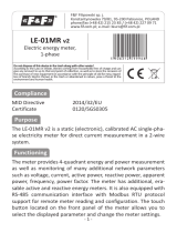
DIN rail mounted Door mounted

2 EN
DIRIS A14 - 542957B - SOCOMEC
1. DOCUMENTATION .............................................................3
2. HAZARDS AND WARNINGS ....................................................4
2.1. Risk of electrocution, burns or explosion ................................4
2.2. Risk of damaging the unit .............................................4
2.3. Liability .............................................................4
3. PRELIMINARY OPERATIONS ....................................................5
4. INTRODUCTION ...............................................................6
4.1. Introduction to the DIRISA14 ..........................................6
4.2. Functions ...........................................................6
4.3. Front views ..........................................................6
4.4. Dimensions ..........................................................6
4.5. Electrical values measured ............................................7
5. INSTALLATION ................................................................8
5.1. Recommendations and safety .........................................8
5.2. DIN rail mounted .....................................................8
5.3. Door mounted .......................................................8
6. CONNECTION .................................................................9
6.1. DIRIS A14 connection - DIN rail mounted ...............................9
6.2. DIRIS A14 connection - door mounted ..................................9
6.3. Connection to the electrical network and to the loads ...................10
6.3.1. Configurable loads based on the network type .................10
6.3.2. Description of the main network and load combinations .........10
7. MID COMPLIANCE ............................................................12
8. COMMUNICATION ............................................................14
8.1. General information .................................................14
8.2. RS485 rules ........................................................14
8.3. Communication structure ............................................15
8.4. Communication tables ...............................................15
9. CONFIGURATION .............................................................16
9.1. Configuring using the screen .........................................16
9.1.1. Example: configuring the choice of current transformer ..........17
9.1.2. Overall view of the programming menu. . . . . . . . . . . . . . . . . . . . . . . .18
9.1.3. Detailed view of the programming menu ......................19
10. USE ........................................................................20
10.1. Detailed view of the energy menu ....................................21
10.2. Detailed view of the measurement menu ..............................22
11. CONNECTION TEST FUNCTION ...............................................23
12. ASSISTANCE ................................................................24
13. CHARACTERISTICS ..........................................................25
14. PERFORMANCE CLASSES ...................................................27
14.1. Specification of the characteristics ...................................27
15. LIST OF ABBREVIATIONS ....................................................28
EN
CONTENTS

3EN
DIRIS A14 - 542957B - SOCOMEC
1. DOCUMENTATION
All documentation on the DIRISA14 is available on the website at
the following address:
www.socomec.com/en/diris-a14

4 EN
DIRIS A14 - 542957B - SOCOMEC
2. HAZARDS AND WARNINGS
The term "device" used in the paragraphs below refers to the DIRISA14.
The assembly, use, servicing and maintenance of this equipment must only be carried out by trained, qualied
professionals.
SOCOMEC shall not be held responsible for failure to comply with the instructions in this manual.
2.1. Risk of electrocution, burns or explosion
• This device must only be installed and serviced by qualied personnel who have in-depth knowledge of
installing, commissioning and operating the device and who have had appropriate training. He or she should
have read and understood the various safety measures and warnings stated in the instructions.
• Before working on the device, disconnect the voltage inputs and short circuit the secondary of each current
transformer (SOCOMEC PTI).
• Always use an appropriate voltage detection device to conrm the absence of voltage.
• Replace all devices, doors and covers before turning on power to this equipment.
• Always power the device with the correct rated voltage.
• Install the unit following the recommended installation instructions and in a suitable electrical cabinet.
Failure to take these precautions could cause death or serious injuries.
2.2. Risk of damaging the unit
To ensure that the unit operates correctly, make sure that:
• The device is correctly installed.
• a maximum voltage at the voltage input terminals of 460 V AC phase-phase or 265 V AC phase-neutral
• The network frequency indicated on the product is observed: 50 or 60 Hz.
• a maximum current of 20 A on the current input terminals (I1, I2 and I3).
Failure to respect these precautions could cause damage to the unit.
2.3. Liability
• Assembly, connection and use must be carried out in accordance with the installation standards currently in
force.
• The device must be installed in accordance with the rules given in this manual.
• Failure to observe the rules for installing this device may compromise the product's intrinsic protection.
• The device must be positioned within an installation which complies with the standards currently in force.
• Any cable which needs to be replaced may only be replaced with a cable having the correct rating.

5EN
DIRIS A14 - 542957B - SOCOMEC
3. PRELIMINARY OPERATIONS
To ensure the safety of personnel and the device, please carefully read the contents of these instructions before
installation.
Check the following points as soon as you receive the package containing the unit:
• The packaging is in good condition,
• The device has not been damaged during transportation,
• The device reference number conforms to your order,
• The package includes:
- 1 device
- 1 sealing kit
- 1 line resistor (ref. 48990019)
- 1 Quickstart

6 EN
DIRIS A14 - 542957B - SOCOMEC
4. INTRODUCTION
4.1. Introduction to the DIRISA14
The DIRISA14 is a MID-certied multifunction meter suitable for monitoring and managing a network's electrical
energy. The DIRISA14 supplies voltage, current, power and energy measurements. Users can easily access all the
product functionalities using the screen and the push buttons. It is tted with an RS485 modbus communication bus.
It can be mounted on a DIN rail (ref. 48250020) or tted on a door (opening 92x92mm) (ref. 48250021).
4.2. Functions
• Electrical parameter measurements: I, U, V, f
• Power, power factor
• Imported and exported active and reactive energy
• RS 485 modbus communication
Description References
DIRISA14 with RS485 modbus communication (DIN rail mounted) 4825 0020
DIRISA14 with RS485 modbus communication (door mounted) 4825 0021
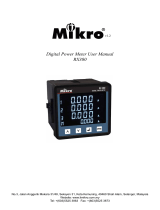
4.3. Front views
6.
4.4.
3.3.
5.5.
2.2.
1.
1.
1. Backlit LCD display
2. Access to energies
and programming
validation.
3. Access to
programming menu.
4. Access to electrical
parameters and power
levels.
5. Metrological LED on
active energy - 0.1Wh /
impulse
6. Information relating to
MID certification.
Ref. 48250021
Ref. 48250020
6.
4.4. Dimensions
Dimensions: in/mm
Ref. 48250020 Ref. 48250021
2.83
72
0.24
6
1.73
44
1.77
45
3.54
90
2.52
64
3.78
96
2.74
69.5
0.94
24
3.78
96

7EN
DIRIS A14 - 542957B - SOCOMEC
4.5. Electrical values measured
Three-phase dimension LCD display Via modbus
communication
Active energy consumed
(Ea+)
total total ∑Ti with 10Wh resolution kWh and 10Wh on Ti and
total ∑Ti
partial total ∑Ti with 10Wh resolution kWh and 10Wh on Ti and
total ∑Ti
produced
(Ea-)
total resolution 10 Wh kWh and 10Wh
partial resolution 10 Wh kWh and 10Wh
Reactive energy consumed
(Er+)
total resolution 10varh kvarh and 10varh
partial resolution 10varh kvarh and 10varh
produced (Er-) total resolution 10varh kvarh and 10varh
partial resolution 10varh kvarh and 10varh
Active power ∑P+,- three-phase resolution 10W kW and 10W
Pi+,- by phase n.a. kW and 10W
Reactive power ∑Q+,- three-phase resolution 10var kvar and 10var
Qi+,- by phase n.a. kvar and 10var
Apparent power ∑S three-phase resolution 10VA kVA and 10VA
If by phase n.a. kVA and 10VA
Power factor ∑ PF+,- three-phase n.a. 1/1000
PFi+,- by phase n.a. 1/1000
Current I1,…IN by phase resolution 10mA mA
Neutral voltage V1,…V3 phase-neutral resolution 10mV 10mV
Phase to phase voltage U1,…U3 phase-phase resolution 10mV 10mV
Frequency f resolution 10mHz 10mHz
Cosj Cosj three-phase resolution 0.01 1/1000
cosji by phase n.a. 1/1000
Current distortion rate THD I1,..I3 by phase n.a. 1/100 %
Voltage distortion rate THD Vi, Ui by phase n.a. 1/100 %
Frequency f n.a. 1/100 of Hz
Max. current Max. I1,..IN by phase
✓ ✓
Max. active power Max. ∑P+ three-phase
✓ ✓
Max. reactive power Max. ∑Q+ three-phase
✓ ✓
Max. apparent power Max ∑S three-phase
✓ ✓
Max. Cosj Max. ∑Cosj three-phase
✓ ✓
Min. active power Max. ∑P- three-phase
✓ ✓
Min. reactive power Max. ∑Q- three-phase
✓ ✓
Min. cosj Max. ∑Cosj- three-phase
✓ ✓
Dated load curve ∑P+ three-phase n.a. W
Energy consumption Ea+ day,
week, month,
n and n-1
total n.a. kWh and 10Wh
Where Ti= Ea+ of tariff i, i=1 - 4; the tariff is selected by the communication bus.
n.a. = not available.

8 EN
DIRIS A14 - 542957B - SOCOMEC
5. INSTALLATION
The paragraphs below describe how to install the device.
5.1. Recommendations and safety
Refer to the safety instructions (section "2. Hazards and warnings", page 4)
• Keep away from electromagnetic interference generator systems,
• Avoid vibrations with accelerations greater than 1 g for frequencies lower than 60 Hz.
5.2. DIN rail mounted
The DIRISA14 unit (ref. 48250020) may be snapped onto a 35 mm DIN rail (EN60715TM35). It must be used in
electrical cabinets.
5.3. Door mounted
The DIRISA14 unit (ref. 48250021) may be tted onto a door with a 92x92mm cutout.
3.62
92
3.62
92
Dimensions: in/mm

9EN
DIRIS A14 - 542957B - SOCOMEC
6. CONNECTION
6.1. DIRIS A14 connection - DIN rail mounted
NC: not connected. May be
used for shielding continuity.
LIYCY-CY
Solid
1.5 mm
2
-> 10 mm
2
Stranded
1 mm
2
-> 6 mm
2
0.47in / 12mm
PZ2
13.27 lb.in / 1.5 Nm max.
6.2. DIRIS A14 connection - door mounted
545521
SOCOMEC SAS
1-4, rue de Westhouse 67230 Benfeld - France
545521
I1
NC
V1
V2 V3
I2
I3
0071
DIRIS A14 MODULAIRE DIRIS A14 ENCASTRABLE
Stranded/Solid
0.2 mm
2
-> 2.5 mm
2
0.27in / 7mm
Flat 3.5 M3
5.31 lb.in / 0.6 Nm max.
Stranded/Solid
0.14 mm
2
-> 1.5 mm
2
0.27in / 7mm
Flat 2.5 M2
2.21 lb.in / 0.25 Nm max.
stranded/Solid
0.2 mm
2
-> 4 mm
2
0.31in / 8mm
Flat 3.5 M3
5.31 lb.in / 0.6 Nm max.

10 EN
DIRIS A14 - 542957B - SOCOMEC
6.3. Connection to the electrical network and to the loads
The DIRISA14 can be used on single-phase, two-phase or three-phase networks.
6.3.1. Congurable loads based on the network type
The table below summarises the loads that it is possible to congure depending on the type of network at the
installation.
Network type Configurable load
1P+N single-
phase
1P+N – 1CT
2P two-phase
2P – 1CT
3P three-phase
3P – 3CT / 3P – 2CT / 3P – 1CT
3P+N three-phase
3P+N – 3CT / 3P+N – 1CT
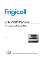
6.3.2. Description of the main network and load combinations
Legend:
3P+N – 3CT
N
V1 V2 V3 VN
V
L1
L2
L3
3 + N
I1
S1 S2
I2
S1 S2
I3
S1 S2
+ -
+
RS485
-
NC
COM - RS485
Three-phase with
neutral load
Current transformer (CT)
Three phase + Neutral
network with 3 current
sensors
= Current transformer
3
3
= Balanced load
3
3
= Unbalanced load
CT
Unbalanced three-phase + neutral (4NBL)
3P+N – 3CT
Unbalanced three-phase (3NBL)
3P - 3CT
N
V1 V2 V3 VN
L1
L2
L3
3 + N
S1 S2 S1 S2 S1 S2
+ -
+
RS485
-
NC
V
I1 I2 I3
COM - RS485 V
I1 I2 I3
COM - RS485
V1 V2 V3 VN
L1
L2
L3
3
S1 S2 S1 S2 S1 S2
+ -
+
RS485
-
NC
These 2 connections for the DIRIS A14 are MID-compliant.

11EN
DIRIS A14 - 542957B - SOCOMEC
Unbalanced three-phase (3NBL)
3P - 2CT
Unbalanced three-phase (3NBL)
3P - 2CT
V
I1 I2 I3
COM - RS485
V1 V2 V3 VN
L1
L2
L3
3
S1 S2 S1 S2 S1 S2
+ -
+
RS485
-
NC
V
I1 I2 I3
COM - RS485
V1 V2 V3 VN
L1
L2
L3
3
S1 S2 S1 S2 S1 S2
+ -
+
RS485
-
NC
The 2CT solution reduces by 0.5% the accuracy of the phase for which the current is deduced by a vector calculation.
Unbalanced three-phase + neutral (4NBL)
3P+N – 1CT
Balanced three-phase (3NBL)
3P – 1CT
V
I1 I2 I3
COM - RS485
N
V1 V2 V3 VN
L1
L2
L3
3 + N
S1 S2 S1 S2 S1 S2
+ -
+
RS485
-
NC
V
I1 I2 I3
COM - RS485
V1 V2 V3 VN
L1
L2
L3
3
S1 S2 S1 S2 S1 S2
+ -
+
RS485
-
NC
Balanced two-phase (2BL) 2P – 1CT Single-phase (1BL) 1P+N – 1CT
V
I1 I2 I3
COM - RS485
V1 V2 V3 VN
L1
L2
2
S1 S2 S1 S2 S1 S2
+ -
+
RS485
-
NC
V
I1 I2 I3
COM - RS485
V1 V2 V3 VN
L1
N
1 + N
S1 S2 S1 S2 S1 S2
+ -
+
RS485
-
NC
I
I01 I02 I03
I
V
I
V
V
I
111
N
V1 V2 V3 VN
L1
L2
L3
I01 I02 I03
V1 V2 V3 VN
V
L1
L2
I01 I02 I03
V1 V2 V3 VN
L1
N
I02 I03
N
V1 V2 V3 VN
I
L1
L2
L3
3
I01 I02 I03
N
V1 V2 V3 VN
V
I
L1
L2
L3
3
I01 I02 I03
N
V1 V2 V3 VN
V
I
L1
L2
L3
333
I01 I02 I03
I01
N
V1 V2 V3 VN
V
I
L1
L2
L3
I01 I02 I03
3+ N
N
V1 V2 V3 VN
V
L1
L2
L3
222
3+ N
1 1 1
Fuse: 0.5 A gG / 0.5 A class CC
This connection for the DIRIS A14 is MID-compliant.

12 EN
DIRIS A14 - 542957B - SOCOMEC
7. MID COMPLIANCE
The following points must be taken into consideration to ensure that the device is used in compliance with directive
MID 2014/32/EU:
• Type of network
The DIRISA14 meters comply with the MID directive for connection to networks: 3P+N–3CT (4NBL),
3P–3CT (3NBL) and 1P+N–1CT (1BL) (see "6.3. Connection to the electrical network and to the loads",
page 10)
• Fitting terminal covers
After connecting the product, ensure that the terminal covers are tted properly and secured by the plastic
seals provided with the product.
• Locking the programming button
Close the button cap by securing it with a seal
• RS485 communication
The information provided via the RS485 COM is transmitted for information only and has no legal value.
• Declaration of MID conformity
The MID declaration of conformity is available on the website: www.socomec.com/en/diris-a14
DIN rail mounted Door mounted
1
1
1
2
3
2 3
2

13EN
DIRIS A14 - 542957B - SOCOMEC
Back cover dismantling (if necessary)
3
2
1
1

14 EN
DIRIS A14 - 542957B - SOCOMEC
8. COMMUNICATION
8.1. General information
The modbus available on the DIRISA14 communicates via an RS485 series link (2 or 3 wires) which is used to
operate products from a PC or an API.
In a standard conguration an RS485 connection is used to connect 32 products to a PC or a controller over 1200
metres.
+ - NC
N 1
+ - NC
N 2
+ - NC
N n
+ - NC
N 1
+ - NC NC - + + - NC
N n
Programmable
machines
Programmable
machines
Other systems
Other systems
Repeater
8.2. RS485 rules
A LIYCY shielded twisted pair must be used. We recommend using a shielded twisted pair with a general LIYCY-CY
shielding in an environment where there is interference or in a very long network with a number of products.
If the distance of 1200 m is exceeded and/or the number of products is greater than 32, a repeater must be added
to enable additional products to be connected.
A 120 Ohm resistor must be xed at both ends of the connection.

15EN
DIRIS A14 - 542957B - SOCOMEC
8.3. Communication structure
The product communicates via a modbus protocol which involves a dialogue in accordance with a master/slave
structure. The communication mode is the RTU (Remote Terminal Unit) mode with hexadecimal characters composed
of at least 8 bits.
Modbus frame structure (master -> slave question):
Slave address Function code Address Number of words to be
read
CRC 16
1 byte 1 byte 2 bytes 2 bytes 2 bytes
To comply with the modbus protocol, the inter-character time must be ≤ 3 silences.
This means the time for 3 characters to be emitted so that the message is processed by the DIRISA14.
In order to use the information correctly, you must use the modbus functions in accordance with the codes:
• 3: to read n words (maximum 128).
• 6: to write one word.
• 16: to write n words (maximum 128).
N.B.:
1 word <=> 2 bytes <=> 16 bits
2 words <=> 4 bytes <=> 32 bits
By selecting the slave address 0, a message is transmitted to all the devices on the network (only for functions 6
and 16).
Note: The response time (question/ response time out) is no more than 250 ms.
8.4. Communication tables
The communication tables and the associated explanations are
available on the DIRIS A14 documentation page on the website at
the following address:
www.socomec.com/en/diris-a14

16 EN
DIRIS A14 - 542957B - SOCOMEC
9. CONFIGURATION
The device can be congured by the Easy Cong conguration software or directly from the DIRIS A 14 screen using
the programming mode. The paragraphs below describe conguring using the screen.
9.1. Conguring using the screen
On the screen, the programming mode is used to modify parameters, such as the type of network, current transformers
or communication parameters. How to browse through the programming mode is described in the following stages:
Go to programming mode
(using a screwdriver, press PROG for 3 seconds)
0,5 mm
3 mm
Go to the next menu
(press PROG once)
Modifies the current screen parameters
Validates the modification
Exit programming mode
(press PROG for 3 seconds)
Note: after 120 seconds of inactivity, the device exits programming mode without saving the changes (except for a
reset).

17EN
DIRIS A14 - 542957B - SOCOMEC
9.1.1. Example: conguring the choice of current transformer
In programming mode (see page 16), go to the "Current Transformer - CT" screen.
Example: changing the transformation ratio to 800/5.
▼
x 20
x1 (10)
x2 (25)
x3 (30)
x4 (40)
x5 (50)
x6 (60)
x7 (75)
x8 (100)
x9 (125)
x10 (150)
x11 (160)
x12 (200)
x13 (250)
x14 (300)
x15 (400)
x16 (500)
x17 (600)
x18 (700)
x19 (750)
x20 (800)
x21 (1000)
x22 (1200)
x23 (1250)
x24 (1500)
x25 (1600)
x26 (2000)
x27 (2500)
▼
x 1
XX = default value

18 EN
DIRIS A14 - 542957B - SOCOMEC
9.1.2. Overall view of the programming menu
Press PROG for 3 seconds and the device will go to programming mode.
The different screens can be accessed by pressing "PROG":
3 seconds
Current transformer
Network type
Communication address
Communication speed
Communication parity
Communication stop bit
Reset the max. and partial energy values to
zero:
Max. 4I, Max.P, Max.Q, Max.S, Max.
cosj, PartialEa+, Partial Er+, Partial Ea-,
PartialEr-
Return to the rst programming menu
screen

19EN
DIRIS A14 - 542957B - SOCOMEC
9.1.3. Detailed view of the programming menu
Current transformer
10, 25, ..., 2000, 2500A
1x
Network type
1BL, 2BL, 3BL, 3NBL, 4BL,
4NBL
Communication address
1, 2, ... 5, ..., 253, 254
Communication speed
4800, 9600, 19200, 38400
Communication parity
no, odd, even
Communication stop bit
1, 2
Reset energies
Max. 4I, Max.P, Max.Q, Max.S,
Max. cosj, PartialEa+, Partial Er+,
Partial Ea-, Partial Er-
Return to the rst programming menu screen
3 seconds
XX = default value

20 EN
DIRIS A14 - 542957B - SOCOMEC
10. USE
The electric dimensions can be accessed using the dedicated buttons: "Energy" and "Measurement". All the
measurements relating to the button scroll down when you keep pressing the appropriate button. The available
measurements are described in the table below:
Energy Measurement
Total imported active and
reactive energy
Instantaneous phase
current
______________ ______________
Total exported active and
reactive energy
Max. phase current
______________ ______________
Partial imported active and
reactive energy
Instantaneous phase/phase
voltages
______________ ______________
Partial exported active and
reactive energy
Instantaneous phase/
neutral voltages
______________ ______________
Frequency
______________
Return to the rst energy
menu screen
Instantaneous three-
phase active, reactive and
apparent powers
______________
Max. three-phase active,
reactive and apparent
powers
______________
Min. three-phase active,
reactive and apparent
powers
______________
Instantaneous three-phase
cosj
______________
Max. three-phase cosj
______________
Min. three-phase cosj
______________
Return to the rst
measuring menu screen
/