


Copyright Notice
COPYRIGHT 2003 Gerber Scientific Products, Inc. All Rights Reserved.
This document may not be reproduced by any means, in whole or in part, without written permission of
the copyright owner.
This document is furnished to support the Sabre Router. In consideration of the furnishing of the
information contained in this document, the party to whom it is given assumes its custody and control
and agrees to the following:
1 The information herein contained is given in confidence, and any part thereof shall not be copied or
reproduced without written consent of Gerber Scientific Products, Inc.
2 This document or the contents herein under no circumstances shall be used in the manufacture or
reproduction of the article shown and the delivery of this document shall not constitute any right or
license to do so.
Printed in USA
GSP and GRAPHIX ADVANTAGE are registered trademarks of Gerber Scientific Products, Inc. Sabre, ART Path, T-
Vac, OMEGA, Support First, and Gerber Gold are trademarks of Gerber Scientific Products, Inc. 3M is a registered
trademark of 3M. Adobe Illustrator and Encapsulated PostScript are registered trademarks of Adobe Systems, Inc.
CASmate-Pro is a registered trademark of ScanVec, Inc. CorelDRAW is a registered trademark of Corel Systems
Corporation. Gatorfoam is a registered trademark of International Paper. Hewlett-Packard is a registered trademark
and HPGL is a trademark of Hewlett-Packard Company. 3-IN-ONE is a registered trademark of the WD-40
Company. Marvel is a trademark of Marvel Oil Company. Microsoft and MS-DOS are registered trademarks of
Microsoft Corp. Signfoam is a trademark of Sign Arts Products Corporation. Windows is a registered trademark of
Microsoft in the U.S. and other countries.

FCC Notice
Warning: Changes or modifications to this unit not expressly approved by the party responsible for
compliance could void the user’s authority to operate the equipment.
Note: This equipment has been tested and found to comply with the limits for a Class A digital device,
pursuant to Part 15 of the FCC rules. These limits are designed to provide reasonable protection against
harmful interference when the equipment is operated in a commercial environment. This equipment
generates, uses, and can radiate radio frequency energy and, if not installed and used in accordance with
the instruction manual, may cause harmful interference to radio communications. Operation of this
equipment in a residential area is likely to cause harmful interference in which case the user will be
required to correct the interference at his own expense.
RS-232 shielded cables must be used with this unit to ensure compliance with the Class A FCC limits.
This Class A digital apparatus complies with Canadian ICES-003.
Cet appareil numérique de la classe A est conforme à la norme NMB-003 du Canada.

Contents
Welcome ....................................................................................................................................... 1
About this manual................................................................................................................................... 1
Conventions ............................................................................................................................................. 2
Customer support ................................................................................................................................... 2
Getting to Know the Sabre .......................................................................................................4
Standard components............................................................................................................................. 4
Electrical cabinet................................................................................................................................... 6
Emergency power shutoff switches................................................................................................... 7
Control pad ........................................................................................................................................... 7
Chip removal system........................................................................................................................... 8
Operational concepts .............................................................................................................................. 8
The role of the design program.......................................................................................................... 8
The role of ART Path ........................................................................................................................... 9
Axes of movement ............................................................................................................................... 9
Machine orientation point................................................................................................................... 9
Job home position................................................................................................................................. 9
Z axis initialization............................................................................................................................. 10
Getting Started...........................................................................................................................11
Power up ................................................................................................................................................ 11
First time or after loading a firmware revision .............................................................................. 11
Normal power-up .............................................................................................................................. 12
Power-up tests .................................................................................................................................... 12
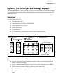
Exploring the control pad and message displays ............................................................................. 13
Control pad ......................................................................................................................................... 13
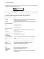
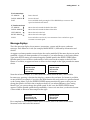
Message displays................................................................................................................................ 15
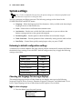
System settings ...................................................................................................................................... 16
Returning to default configuration settings ................................................................................... 16
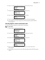
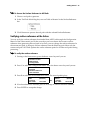
Choosing the language for message displays ................................................................................ 16
Choosing English or metric measurement units............................................................................ 17
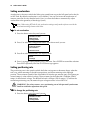
Setting acceleration ............................................................................................................................ 18
Setting positioning rate ..................................................................................................................... 18
Using table protection ....................................................................................................................... 19
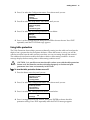
Setting start delay............................................................................................................................... 20
Selecting the job data type ................................................................................................................ 20
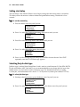
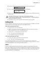
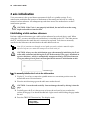
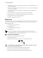
Cutting tools........................................................................................................................................... 21
Collets .................................................................................................................................................. 21
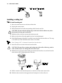
Installing a cutting tool...................................................................................................................... 22
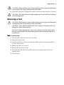
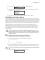
Removing a tool..................................................................................................................................... 23
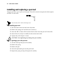
Installing and replacing a pen tool ..................................................................................................... 24

Using the chip removal system ........................................................................................................... 25
Removing the pressure foot assembly................................................................................................ 26
Changing the pressure foot pad....................................................................................................... 27
Understanding Surface Reference....................................................................................................... 27
Setting the surface reference............................................................................................................. 28
Verifying surface reference at the Sabre ......................................................................................... 29
Z axis initialization................................................................................................................................ 30
Establishing a table surface reference.............................................................................................. 30
Establishing material surface reference........................................................................................... 31
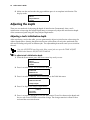
Adjusting the depth .............................................................................................................................. 32
Adjusting a tool's initialization depth ............................................................................................. 32
Temporarily adjusting the initialization depth of a tool............................................................... 33
Mat milling............................................................................................................................................. 33
Safety guidelines ................................................................................................................................ 33
Milling the mat ................................................................................................................................... 34
Routing ........................................................................................................................................37
Safety guidelines ................................................................................................................................... 37
Pre-job checklist..................................................................................................................................... 38
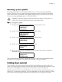
Warming up the spindle....................................................................................................................... 39
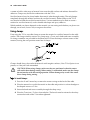
Holding down material........................................................................................................................ 39
Using clamps....................................................................................................................................... 40
Using the T-Vac .................................................................................................................................. 41
Using sacrificial material................................................................................................................... 41
Material hold down guidelines ........................................................................................................ 42
Setting speed and feeds........................................................................................................................ 44
Changing spindle speed.................................................................................................................... 44
Overriding the X,Y feed rate............................................................................................................. 45
Position control...................................................................................................................................... 46
Returning to table 0,0 (orientation point) ....................................................................................... 47
Routing the job....................................................................................................................................... 47
Emergency stopping .......................................................................................................................... 49
Pausing and restarting routing......................................................................................................... 49
Verifying job size and boundaries ................................................................................................... 50
Setting and changing job home position......................................................................................... 50
Displaying elapsed job time.............................................................................................................. 51
Manual routing...................................................................................................................................... 51
Controlling the spindle air on ATC equipped machines................................................................. 52
Changing motors................................................................................................................................... 53
Maintenance .............................................................................................................................. 54
Daily inspection..................................................................................................................................... 54
Daily cleaning ........................................................................................................................................ 54
Recommended cleaning supplies .................................................................................................... 54
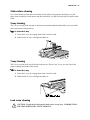
Table surface cleaning ....................................................................................................................... 55
X way cleaning.................................................................................................................................... 55
Y way cleaning.................................................................................................................................... 55
Lead screw cleaning........................................................................................................................... 55
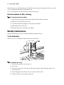
Electrical cabinet air filter cleaning.................................................................................................. 56
Weekly maintenance............................................................................................................................. 56
Z axis lubrication................................................................................................................................ 56
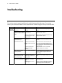
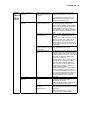
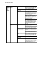
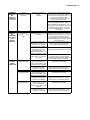
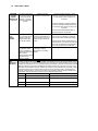
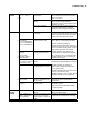
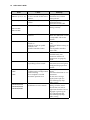
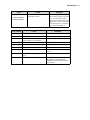
Troubleshooting ........................................................................................................................57

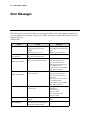
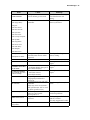
Error Messages .......................................................................................................................... 64
Options........................................................................................................................................ 68
High Frequency Spindle Option ...................................................................................................... 68
Mist Coolant Option .......................................................................................................................... 68
T-Vac Option....................................................................................................................................... 69
Engraver and Engraver Vacuum Options ...................................................................................... 69
Automatic Tool Changer Option ..................................................................................................... 69
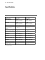
Specifications.............................................................................................................................70
Index ............................................................................................................................................ 71


Welcome 1
Welcome
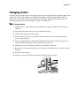
Thank you for purchasing the Sabre™ Router. The Sabre is a router/engraver for use in
dimensional sign making, woodworking, and parts fabrication. It offers high-speed routing of
lettering and graphic designs, dependability, and ease of use, minimal maintenance
requirements, and configuration flexibility. The Sabre can cut designs from a variety of
materials
−
foams, plastic, wood, composites, and non-ferrous metals
−
as well as draw all types
of text and graphics.
The Sabre is available in two table sizes: 4 foot x 4 foot (122 cm x 122 cm) and 4 foot x 8 foot (122
cm x 244 cm). A variety of options enhance operation. The standard 3¼ hp router motor may be
replaced with the High Frequency Spindle Option for quiet, variable speed operation up to
24,000 rpm. (The Engraver Option provides the accuracy of an engraver with the cutting
capabilities of a router in a single system.) The T-Vac
Vacuum Table Option provides superior
holddown for a wide variety of material size and types.
The Sabre can rout designs created by using many standard design programs — Composer in
Gerber OMEGA™ or GRAPHIX ADVANTAGE
®
, CorelDRAW
®
, and CASmate
®
. Regardless of
the program used to create the design to be routed, the Gerber ART Path™ software prepares
the design for routing by the Sabre. ART Path allows you to generate tool paths of varying
depths, then output the job to the Sabre. When used with design programs other than Gerber
programs, the open architecture ART Path Software Option enables you to import standard file
formats into ART Path for tool path generation.
WARNING: The Sabre is a computer-controlled machine tool and should be used
only by trained operators. The safety guidelines in this manual must be followed at
all times to avoid risk of injury.
About this manual
This manual covers the basic information needed for using the Sabre. The manual is arranged as
follows:
♦
Getting to Know the Sabre describes the items that make up the Sabre system and
introduces concepts that will help you operate the Sabre safely and efficiently.
♦
Getting Started guides you through the process of setting up the Sabre, power up,
Sabre system settings to meet your needs, installing and removing tools, and more.
♦
Routing provides detailed instructions for routing.
♦
Maintenance outlines the procedures you should perform to keep the Sabre in good
running order.

2 Sabre Owner’s Guide
♦
Troubleshooting suggests ways to analyze and respond to problems.
♦
Error Messages lists messages that you may see on your Sabre screen, the possible
causes and suggested remedies.
♦
Options provides an overview of options which may be purchased with the Sabre.
♦
Specifications outlines size and performance specifications.
For detailed information regarding ART Path, OMEGA, or GRAPHIX ADVANTAGE, refer to
your ART Path, OMEGA, or GRAPHIX ADVANTAGE User's Guides or on-line Help.
Conventions
Special information in this manual is presented in notes, cautions, and warnings as follows:
Note: A note contains important information that could affect successful completion of a task.
CAUTION: A caution statement contains information which, if not observed, could
result in damage to the equipment.
WARNING: A warning statement contains information which, if not observed,
could result in personal injury.
This type style is used to represent what is displayed on the Sabre’s LCD display screen.
Customer support
If you have questions regarding using, maintaining, or troubleshooting the Sabre or the ATC,
please contact your Gerber distributor or the Gerber Router Support Group at:
phone: 860-528-1028
fax: 860-290-5568
e-mail: [email protected]
www.gspinc.com
If you are a Support First™ member, use your toll-free assistance number (for more information
on Support First, call 860-528-1028).
For field service telephones, the number is 800-828-5406 (US and Canada). International
customers call 860-643-1515.
Gerber FastFacts™ (answers to technical and service questions) telephone number is 800-222-
7446. FastFacts are also available on the Gerber web site.
Please use a phone that is close to your system and have the following information available
when you call:

Welcome 3
♦
Microsoft
Windows
version number
♦
GSP
system ID number (System Identification String in Gerber System Tray or in GSP
Setup of GRAPHIX ADVANTAGE)
♦
System serial number (on security block)
♦
Sabre serial numbers (on back of beam and electrical cabinet)
If you have OMEGA or GRAPHIX ADVANTAGE, please have the following information ready:
♦
OMEGA or GRAPHIX ADVANTAGE program disks
♦
Windows hardware utilities disks
♦
OMEGA or GRAPHIX ADVANTAGE, and Windows user manuals

4 Sabre Owner’s Guide
Getting to Know the Sabre
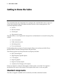
This section describes the components that accompany the standard Sabre router so that you
will be able to identify them and understand their function in the routing operation. The
standard components include:
♦
Tool kit
♦
Electrical cabinet
♦
Control pad
♦
Chip removal system
The Sabre follows a set of operational concepts that are fundamental to successful routing. They
include:
♦
Axes of movement
♦
Table orientation point
♦
Job home position
♦
Z axis initialization
Understanding these concepts will make using the Sabre easier and more reliable. Please
become familiar with these concepts before using the Sabre.
The following options may be purchased to accompany the Sabre:
♦
Mist Coolant Option
♦
High Frequency Spindle Option
♦
T-Vac Option
♦
Engraving Option
♦
Engraver Vacuum Option
♦
Automatic Tool Changer (ATC) Option
Please see “Options” section for descriptions of these options. Use of the T-Vac Option is
described in this section of this manual. Each option comes with its own user guide.
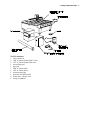
Standard components
The Sabre is shipped assembled and is installed by an Gerber-authorized installer.

Getting to Know the Sabre 5
Tool kit contents
1 tool wrench set
3 .250" or 6 mm Gerber Gold™ tools
3 .125" or 3 mm Gerber Gold tools
1 mat milling tool
1 pen tool
1 .250" or 6 mm collet
1 .125" or 3 mm sleeve
1 initialization gage
1 pressure foot pad (small)
4 spare fuses, various sizes
6 clamp assemblies

6 Sabre Owner’s Guide
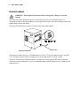
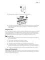
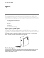
Electrical cabinet
WARNING: Do not open the electrical cabinet. Dangerous voltages exist in the
interior.
The electrical cabinet distributes power to the Sabre and some of its related devices. It is
designed to stand on the floor behind or to the right of the router. This location helps protect the
cabinet from coolant and debris.
The main ON/OFF power switch is located on the side of the cabinet.
The electrical cabinet also has a switched outlet (115 VAC, 15 amp for domestic units, and 220
VAC, 20 amp for export units) to supply power to the chip removal system vacuum.
The front of the electrical cabinet contains a window for viewing eight LED status indicators.
You may use these indicators to assist in troubleshooting under the direction of a Gerber service
representative.
Power cord
Electrical cabinet

Getting to Know the Sabre 7
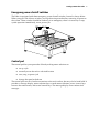
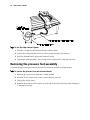
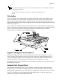
Emergency power shutoff switches
The Sabre is equipped with three emergency power shutoff switches, located as shown below.
When you press one of these switches, you trip the main power breaker, removing all power to
the system. These switches should be used only in an emergency when it is necessary to stop
system operation immediately, not to pause a job.
Control pad
The control pad lets you operate the Sabre by making menu selections to:
♦
set up a job
♦
manually move the tool to a desired location
♦
start, stop, or pause a job
♦
change the speed or feed rate
The control pad rests on a bracket convenient to the work surface, but may also be hand held. It
provides a message display, menu selection keys to make menu selections, move (arrow) keys
to move the router motor, and several control keys. The message display shows menus and
messages.

8 Sabre Owner’s Guide
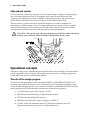
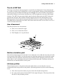
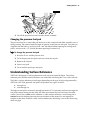
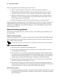
Chip removal system
The chip removal system helps keep the work area clean during routing by vacuuming chips
into a customer-supplied vacuum. It is equipped with a pressure foot that rests on the
workpiece and slides easily over the workpiece surface during routing. The pressure foot
applies downward force on the material to keep it from lifting during routing.
The chip removal system comes fully installed but requires a customer-supplied 3 hp
(minimum), 16 gallon vacuum with a 2.5" (64 mm) diameter hose opening. A hose supplied
with the Sabre connects to the vacuum hose. The Sabre hose contains a ground strap cable,
which protects the Sabre from static discharges that can interrupt operation.
CAUTION: The ground strap cable must be properly installed in order to discharge
built-up static electricity which could affect the operation of the system.
Operational concepts
The Sabre is one part of a complete design and production system. Routing a job on the Sabre is
actually the culmination of a design and output process that involves a design program, the
Gerber ART Path software, and the Sabre controls.
The role of the design program
You will use a design program such as the Gerber OMEGA or GRAPHIX ADVANTAGE to
create the sign or image you want to rout. The Sabre can also rout designs created by a wide
variety of other design programs. If you do not use OMEGA or GRAPHIX ADVANTAGE, the
design program you use must be able to produce one of the following formats:
♦
AI (Adobe Illustrator® format version 1.1 only)
♦
EPS (Encapsulated PostScript®, Adobe Illustrator format)
♦
DXF (Drawing Interchange File Format)
♦
PRN (Hewlett-Packard
Graphics Language, or HPGL™)
♦
G Codes, which are interpreted by the G Code feature (Requires the use of
Hyperterminal and the assistance of a Gerber technician.)

Getting to Know the Sabre 9
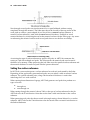
The role of ART Path
The image created by the design program is essentially two-dimensional. It may be displayed
on a screen, cut from vinyl, or printed on a vinyl or paper printer. Routing is three-dimensional,
involving not just the outline of the design, but the depth of cut, the tool radius and geometry,
and material thickness and surface characteristics. ART Path generates tool paths from design
elements. The ART Path user enters depth, speed, and tool information that ART Path uses to
generate the tool path. ART Path then controls output of the file to the Plot Spooler or GQ
Manager queue, which communicates with the Sabre firmware to control routing the design.
This guide does not describe use of ART Path. Please refer to the
ART Path and Auto-carve User's
Guide
for further information.
Axes of movement
The Sabre has three axes of movement:
♦
The X-axis is from left to right.
♦
The Y-axis is from front to back.
♦
The Z (depth) axis is up and down.
Machine orientation point
The machine orientation point locates the X-axis at 0,0, the Y-axis at 0,0 and raises the tool to the
Z axis position of 0,0. When you turn the power on, the Sabre prompts you to orient the system.
The Sabre locates the machine orientation point at the 0,0 position (the front, left corner of the
Sabre table) as well as the highest elevation of the tool above the table. The Sabre calculates all
future moves on the table relative to this point.
Job home position
The job home position is the point on the router table where you want the job to start. It
corresponds to the start position in the job data. Job home position may be set in the following
ways:
♦
Allow the tool position when you press Start to be the job home position.
♦
Set a pre-position (move) from the ART Path output dialog box. The tool position after
the move is the job home position.

10 Sabre Owner’s Guide
♦
Press the control pad move keys to move the tool to the desired position and press the
Home function key.
Note: Use the Home key only if you have already pressed Start and wish to establish a different
job home position.
The job home position must allow sufficient room for the job to fit within the active cutting area.
If job home position causes the job to extend beyond the routing area, the Sabre displays an
error message indicating that the job exceeds table boundaries. To continue, you will have to
change the job home position, ART Path offset, or number of repeats so that it fits within table
boundaries.
Z axis initialization
Z-axis movement is the up and down movement of the tool. Z-axis initialization establishes the
location of the cutting tool relative to the router table (or sacrificial material) surface and the
workpiece material surface. All subsequent up and down moves are made relative to the Z
initialization position. If the Z-axis is not properly initialized, the tool will cut at the wrong
depth and could cut into the table.
The Z-axis may be initialized for two types of routing: through-cutting and non-through
cutting. When initialized for through-cutting, the Z-axis is initialized to the table (or sacrificial
material) surface and the Sabre tool cuts entirely through the workpiece during cutting. When
initialized for non-through cutting, the Z-axis is initialized to the material surface and the Sabre
tool plunges into the material to the depth specified in ART Path relative to the surface of the
material. Refer to the section “Z axis initialization” for detailed instructions.

Getting Started 11
Getting Started
Before using the Sabre to cut a job, perform these preliminary steps:
♦
Connect the chip removal system ground strap.
♦
Make sure all ground straps are securely connected to the ground stud on the rear of
the electrical cabinet.
♦
Verify that the table mats have been milled to create a perfectly flat surface.
♦
Power up.
♦
Explore the control pad. Refer to the Sabre Router Menu Structure card in the back of
this manual for details about the menus.
♦
Select the display language.
♦
Select English or metric measurement units.
Power up
There are two power-up sequences:
♦
the first time the Sabre is turned on or after loading a new firmware revision
♦
normal power-up
Since the Sabre is turned on and tested at the factory before shipment, you normally will never
see the “first-time” power-up sequence when you start your router for the first time at your
facility. However, you will see this sequence after loading a new firmware revision.
First time or after loading a firmware revision
After loading a new firmware revision, you must specify the router type (Sabre 404 or 408), the
cutting motor type (router motor, high frequency spindle, or ATC spindle), and set the
orientation. The sequence and displays are as follows:
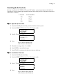
To start up the first time or after a firmware revision
1
After the firmware is loaded, the display shows:
SELECT MACHINE
Sabre 404
A: Change

12 Sabre Owner’s Guide
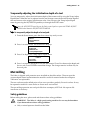
2
Press A to toggle between Sabre 404 and Sabre 408. Press ENTER when it displays
your router type. The display shows:
Spindle/Router
Router
A: Change
3
Press A to toggle between Router, Spindle, and ATC Spindle. Press ENTER when the
display shows the motor type installed on your router. The display shows:
ORIENTATION
A: Orient System
WARNING: The Sabre will move quickly. Stand away from the table.
CAUTION: If you move the carriage into the front left corner so that it stops against
the corner, an error will occur. Turn power off and on at the electrical cabinet, so
that the Sabre repeats orientation.
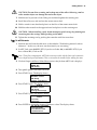
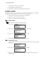
4
Press A. The Sabre moves the tool to the machine orientation position and raises the
tool. The display shows:
STATUS
SABRE: Idle
JOB: Not Ready
When this STATUS message appears, the Sabre is ready for use.
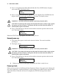
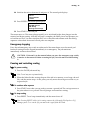
Normal power-up
1
Turn on the main power switch on the electrical cabinet. The switch should be
pointing up.
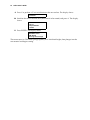
2
The display shows:
ORIENTATION
A: Orient System
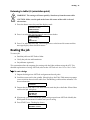
WARNING: The Sabre will move quickly. Stand away from the table.
CAUTION: If you move the carriage into the front left corner so that it stops against
the corner, an error will occur. Turn power off and on at the electrical cabinet, so
that the Sabre repeats orientation.
3
Press A. The Sabre moves the tool to the machine orientation position and raises the
tool. The display shows:
STATUS
SABRE: Idle
JOB: Not Ready
4
Whenever this STATUS message is displayed, the Sabre is ready for use.
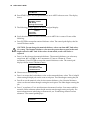
Power-up tests
When you turn power on, the Sabre performs diagnostic self-tests. If an error occurs during self-
tests, the system emits a continuous beep or a series of beeps. Press RESET on the control pad to
repeat the self-test. When the self-tests are complete, the STATUS message shown above
appears.
Page is loading ...
Page is loading ...
Page is loading ...
Page is loading ...
Page is loading ...
Page is loading ...
Page is loading ...
Page is loading ...
Page is loading ...
Page is loading ...
Page is loading ...
Page is loading ...
Page is loading ...
Page is loading ...
Page is loading ...
Page is loading ...
Page is loading ...
Page is loading ...
Page is loading ...
Page is loading ...
Page is loading ...
Page is loading ...
Page is loading ...
Page is loading ...
Page is loading ...
Page is loading ...
Page is loading ...
Page is loading ...
Page is loading ...
Page is loading ...
Page is loading ...
Page is loading ...
Page is loading ...
Page is loading ...
Page is loading ...
Page is loading ...
Page is loading ...
Page is loading ...
Page is loading ...
Page is loading ...
Page is loading ...
Page is loading ...
Page is loading ...
Page is loading ...
Page is loading ...
Page is loading ...
Page is loading ...
Page is loading ...
Page is loading ...
Page is loading ...
Page is loading ...
Page is loading ...
Page is loading ...
Page is loading ...
Page is loading ...
Page is loading ...
Page is loading ...
Page is loading ...
Page is loading ...
Page is loading ...
Page is loading ...
Page is loading ...
Page is loading ...
-
 1
1
-
 2
2
-
 3
3
-
 4
4
-
 5
5
-
 6
6
-
 7
7
-
 8
8
-
 9
9
-
 10
10
-
 11
11
-
 12
12
-
 13
13
-
 14
14
-
 15
15
-
 16
16
-
 17
17
-
 18
18
-
 19
19
-
 20
20
-
 21
21
-
 22
22
-
 23
23
-
 24
24
-
 25
25
-
 26
26
-
 27
27
-
 28
28
-
 29
29
-
 30
30
-
 31
31
-
 32
32
-
 33
33
-
 34
34
-
 35
35
-
 36
36
-
 37
37
-
 38
38
-
 39
39
-
 40
40
-
 41
41
-
 42
42
-
 43
43
-
 44
44
-
 45
45
-
 46
46
-
 47
47
-
 48
48
-
 49
49
-
 50
50
-
 51
51
-
 52
52
-
 53
53
-
 54
54
-
 55
55
-
 56
56
-
 57
57
-
 58
58
-
 59
59
-
 60
60
-
 61
61
-
 62
62
-
 63
63
-
 64
64
-
 65
65
-
 66
66
-
 67
67
-
 68
68
-
 69
69
-
 70
70
-
 71
71
-
 72
72
-
 73
73
-
 74
74
-
 75
75
-
 76
76
-
 77
77
-
 78
78
-
 79
79
-
 80
80
-
 81
81
-
 82
82
-
 83
83


Ask a question and I''ll find the answer in the document
Finding information in a document is now easier with AI
Related papers
-
Gerber Dimension 200 User manual
-
-
-
Gerber Omega 7.0 Software for the Printing System Operating instructions
-
-
-
-
-
-
Other documents
-
BodyCraft SpaceWalker Treadmill Operating instructions
-
ADJ Accu Spot 575 User manual
-
Wen 21C User guide
-
 master mechanic 167396 Operating instructions
-
BakkerElkhuizen BNEQNOTE350 Datasheet
-
-
MIMAKI ME-II Operating instructions
-
Ekena Millwork BMSTRF02X144TRBL Installation guide
-
omtech LRA-6000-00 User manual
-
Global Machinery Company DEC007EN User manual
