Page is loading ...

Read instructions before starting installation*
Review of “Tricks of the Trade” on the reverse will assist with installation.
For purposes other than water, contact JCM Industries for application and product assistance.
1. Clean and scrape pipe. Remove any scale, pipe wrap, debris or dirt that may interfere with the
complete sealing of the gasket. Inspect pipe for integrity, size, outside diameter and surface
irregularities. Confirm the proper size and range of repair clamp. Inspect fitting to ensure all
parts are included.
2. Lubricate the pipe and the fitting gasket with soapy water. Do not use oil base pipe
lubricant. Loosen nuts of bolts and back nuts to the end of the bolt (complete removal of bolts
is not necessary). Release oval necked bolts from lug ears and open the clamp.
3. For Models 101, 103 - Place clamp on pipe and center over damaged area. Tuck tapered
gasket in place; mesh finger lugs and rotate clamp in direction of arrow to smooth tapered
gasket flap. Position bolting lug for easy access to continued bolt tightening. Engage bolts in
receiver lugs and finger tighten to hold in place. Begin bolt tightening
sequence. See step 4.
For 102, 104 Multi Band Clamps - with multi lug segments. One section has “closed ears” (A)
and “open ears” (B) for bolt engagement. Locate lug segment with open “ear” to loosen bolts.
Loosen bolts of other lug segments. Do not remove bolts.
Open clamp at open ear lug segment and place clamp on pipe so that
gasket flap is on top is facing you. Bring back half of clamp around pipe.
Feed tapered gasket end into place, mesh top lug fingers into “open ears”
and engage bolts. Rotate clamp in direction of arrow to smooth tapered
gasket flaps. Finger tighten bolts to hold in place. Begin tightening bolts to
proper torque values. Continue around pipe at each lug segment. Avoid
tightening lugs to metal bound at any one segment - gaps between lugs
should be approximately even on both sides. Continue bolting sequence to proper torque values
below.
4. Tighten all bolts evenly to the following torque values, ensure torque values with calibrated field
torque wrench:
5/8” Bolts to 70 Foot Pounds
3/4” Bolts to 90 Foot Pounds
5. Complete installation of fitting, return after approximately 15 minutes and confirm minimum
bolt torque levels have been maintained.
For JCM 103 and 104 Tapped Clamps, proceed with tapping process.
*Ensure fitting is suitable for application (confirm size, materials, pressure ratings, line content, meets local governing & association standards, etc.).
Pipeline operation forces, including pressure fluctuations, thermal expansion/contraction, movement/shifting, etc. will influence the success of the
application. Proper anchorage, restraint, harnessing, thrust blocks or other devices must be provided to prevent pipe movement (lateral, angular, axial) or
pipe pullout from the bolt-on fitting. Inspection of the pipe integrity is the responsibility of the end user. JCM recommends the use of calibrated torque
wrench. Failure to follow installation instructions will result in voided product warranty.
For application review or questions contact JCM Industries at 1-800-527-8482, 903-832-2581
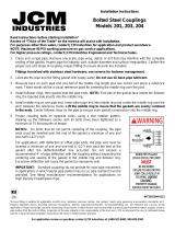
Installation Instructions
Models 101, 103, 102 and 104
Universal Clamp Couplings
INT101-0115

Years of field experience, special applications and product testing have revealed many subtleties regarding application and
installation of repair clamps. For maximum performance under adverse conditions take advantage of the JCM “Tricks of the
Trade.”
• Always clean and lubricate pipe with water or soapy water. This helps overcome friction when rotating the clamp to smooth the gasket.
Do not use oil base pipe lubricant; the oil does not disperse, leaves residue and prevents the gasket from sealing/adhering to the pipe
wall. Use water solvent lubricant. Use of a mirror will assist inspection of backside of pipe or pipe in cramped, limited space.
• Place a reference mark on the pipe back from the damaged area to help in centering clamp over break.
Clamps provide maximum performance when centered over damage area.
• For installation on pipe under pressure: lubricate the clamp gasket with soap/water mixture, assemble clamp
on the pipe beside the damaged area, lightly engage bolts and slid the clamp over the damaged area,
ensure tapered gasket lays flat without curl or fold, proceed with installation steps.
• Breaks involving deflected pipe require a wider clamp. JCM lugs will articulate, permitting clamp to better conform to pipe.
• Damage involving large holes or massive pitted areas - use stainless steel plate over large holes (under repair clamp) to provide the
gasket a surface to seal against.
• Drill holes in the ends of splits or cracks to relieve forces which could cause splits to continue.
• Clamp performance drops when gap between pipe ends is larger than 1/2”. Use a stainless steel spacer to fill or to place over gap.
• Leave sufficient pressure on a broken line to prevent intrusion of foreign matter to prevent excessive line contamination.
• With pressure reduced, spraying water will cease as soon as water level rises above break.
• Lubricating clamp bolts will ease clamp installation and assure proper torquing of bolts.
Making Larger Clamp From Smaller Clamps
Longer than normal gasket tapers permit joining of Universal Clamp Couplings of like width and type to make a larger
clamp. For instance, a 6” and 8” clamp can be joined to make a 14” clamp. This provides you with “on hand” capability to
make repairs on larger pipe sizes.
• Determine which clamps are available to make needed clamp, usually 2 or 3 clamps
are sufficient. It is recommended that clamps to be joined be not more than one
nominal size apart. Join clamps with ranges that when combined include O.D. of
pipe to be repaired. For Example: Required clamp is 14” to fit 16.44 O.D. Combining
a 101-0905-12 (range 8.99 to 9.39) and a 101-0690-12 (range 6.84 to 7.25) will
make a clamp with a range of 15.84 to 16.64.
• Prior to joining clamps, reduce the curvature of the recessed bridge plate (as shown
in photo) to slightly less than curvature of pipe to be repaired. This is done by laying
bridge plate between two 2” x 4”’s and hitting with a small sledge hammer.
• Install as a multi-band clamp, making sure to tighten bolts evenly keeping gaps between lugs approximately even.
Tricks of the Trade for Installation
Models 101, 103, 102 and 104
Universal Clamp Couplings
/


