Page is loading ...

Wandfluh AG
Postfach
CH-3714 Frutigen
Tel: +41 33 672 72 72
Fax: +41 33 672 72 12
Email: [email protected]
Internet: www.wandfluh.com
Page 1
Edition 12 14
SD636bae.pdf
Operating instructions to Enhanced Controller module SD6
OPERATING INSTRUCTIONS
ENHANCED CONTROLLER MODULE
SD6

Wandfluh AG
Postfach
CH-3714 Frutigen
Tel: +41 33 672 72 72
Fax: +41 33 672 72 12
Email: [email protected]
Internet: www.wandfluh.com
Page 2
Edition 12 14
SD636bae.pdf
Operating instructions to Enhanced Controller module SD6
Contents
1 General information
3
2 Product description 3
................................................................................................................................................................................. 32.1 General
................................................................................................................................................................................. 32.2 Field of application
................................................................................................................................................................................. 32.3 Conformity
................................................................................................................................................................................. 32.4 Labelling of the product
................................................................................................................................................................................. 42.5 Type code
................................................................................................................................................................................. 52.6 Technical Data
................................................................................................................................................................................. 82.7 Block diagram
3 Safety rules 9
................................................................................................................................................................................. 93.1 Installation / Commissioning / Parameterisation
4 Construction and Function 10
................................................................................................................................................................................. 104.1 Introduction
................................................................................................................................................................................. 104.2 Description of the Function
................................................................................................................................................................................. 104.3 Characteristic optimisation
................................................................................................................................................................................. 114.4 SD6 State machine
................................................................................................................................................................................. 124.5 Operating mode
................................................................................................................................................................................. 124.6 Analogue inputs
................................................................................................................................................................................. 134.7 Cablebreak detection
................................................................................................................................................................................. 134.8 Digital inputs
................................................................................................................................................................................. 144.9 Input for digital sensor
................................................................................................................................................................................. 154.10 Outputs
................................................................................................................................................................................. 154.11 Controller Modes
................................................................................................................................................................................. 214.12 Mode of operation
5 Operating and Indicating elements
23
................................................................................................................................................................................. 235.1 General
................................................................................................................................................................................. 235.2 Screw terminator view
................................................................................................................................................................................. 245.3 Control elements
6 Commissioning
26
................................................................................................................................................................................. 266.1 Connection instructions
................................................................................................................................................................................. 286.2 Connection examples
7 Settings 29
................................................................................................................................................................................. 297.1 Introduction
................................................................................................................................................................................. 297.2 Tips for the first commissioning
................................................................................................................................................................................. 307.3 Start up help
................................................................................................................................................................................. 327.4 Default settings
................................................................................................................................................................................. 347.5 File-Menu
................................................................................................................................................................................. 377.6 Profile-Menu
................................................................................................................................................................................. 437.7 Parameters-Menu
................................................................................................................................................................................. 527.8 Configuration-Menu
................................................................................................................................................................................. 717.9 Commands-Menu
................................................................................................................................................................................. 737.10 Fieldbus-Menu
................................................................................................................................................................................. 737.11 Setup mode
................................................................................................................................................................................. 747.12 Analysis-Menu
................................................................................................................................................................................. 797.13 Help-Menu
8 System does not work 80
................................................................................................................................................................................. 808.1 Procedure
9 PASO DSV/SD6 Installation and Operation 81
................................................................................................................................................................................. 819.1 System presupposition
................................................................................................................................................................................. 819.2 Installation
................................................................................................................................................................................. 819.3 Connection to the Wandfluh card
................................................................................................................................................................................. 829.4 Mode "Off Line" and "On Line"
................................................................................................................................................................................. 829.5 Communication start up
................................................................................................................................................................................. 839.6 Communication interruption
................................................................................................................................................................................. 849.7 Program description
................................................................................................................................................................................. 869.8 Starting of PASO DSV/SD6
................................................................................................................................................................................. 879.9 Store parameter
................................................................................................................................................................................. 879.10 Limiting value error
................................................................................................................................................................................. 889.11 Description of Commands
10 Disposal 89
11 Additional information
89

Wandfluh AG
Postfach
CH-3714 Frutigen
Tel: +41 33 672 72 72
Fax: +41 33 672 72 12
Email: [email protected]
Internet: www.wandfluh.com
Page 3
Edition 12 14
SD636bae.pdf
Operating instructions to Enhanced Controller module SD6
1 General information
This operating instructions makes it possible to use the SD6-Electronics safely and according to specification.
The operating instructions includes instructions which Wandfluh as the manufacturer, or its resale organisations
(Wandfluh sister companies or distributors), provide to users within their duty to instruct.
For this purpose, the operating instructions mainly includes:
· information about use according to specification, installation and commissioning of the SD6-Electronics
· information about safety in dealing with control.
2 Product description
2.1 General
The SD6-Electronics is integrated in a case for top-hat rail fastening. The connections are provided by terminal
screw blocks.
2.2 Field of application
The field of application of the SD6-Electronics is situated in the industrial field.
2.3 Conformity
The SD6-Electronics have been developed and tested in accordance with the latest technical standards. Applied
in particular was the EU Guideline 2004/108/EG (EMC Guideline).
2.4 Labelling of the product
With the PC parameterisation software PASO DSV/SD6, the following information can be directly read-off the
SD6-Electronics (=electronic type code):
· Part number
· Serial number
· Software version
· Firmware version
· Card type
· Hardware configuration

Wandfluh AG
Postfach
CH-3714 Frutigen
Tel: +41 33 672 72 72
Fax: +41 33 672 72 12
Email: [email protected]
Internet: www.wandfluh.com
Page 4
Edition 12 14
SD636bae.pdf
Operating instructions to Enhanced Controller module SD6
2.5 Type code

Wandfluh AG
Postfach
CH-3714 Frutigen
Tel: +41 33 672 72 72
Fax: +41 33 672 72 12
Email: [email protected]
Internet: www.wandfluh.com
Page 5
Edition 12 14
SD636bae.pdf
Operating instructions to Enhanced Controller module SD6
2.6 Technical Data
2.6.1 General specifications
Design
Integrated in electronic case for top-hat rail clamping
Dimension
Amplifier and Basic Controller: 105 x 114 x 22.5mm
Enhanced Controller: 105 x 114 x 45mm
Amplifier and Controller with Profibus: 105 x 114 x 45mm
Mounting
For top-hat rail clamping
Weight
Amplifier and Basic Controller: 130g
Enhanced Controller: 220g
Amplifier and Controller with Profibus: 240g
Connection
Terminal screw blocks, max dimension 2.5mm
2
1 USB interface (connector type B)
Protection class
IP30 acc. to EN 60 529
2.6.2 Electrical specifications
Supply voltage
(depending on the type)
24 VDC
or 12 VDC
Voltage range
Supply voltage 24 VDC: 21 ... 30 VDC
Supply voltage 12 VDC: 10.5 ... 15 VDC
Ripple on supply voltage
< ±5 %
Fuse
Customer must integrate a slow fuse into his electrical system
Temperature drift
< 1% with DT = 40°C
No load current
40 ... 50 mA
Max. solenoid current
24VDC version 1.8 A
12VDC version 2.3 A
Analogue inputs
2 differential inputs 10-Bit (analogue input 1 + 2)
2 differential inputs 16-Bit (analogue input 3 + 4)
All inputs are not galvanically separated
SD6362DX4-BX
Analogue input 1:
Analogue input 2:
Analogue input 3:
Analogue input 4:
0...±10VDC
0...20mA, 4...20mA
0...±10VDC
0...20mA, 4...20mA
SD6362DX5-BX
Analogue input 1:
Analogue input 2:
Analogue input 3:
Analogue input 4:
0...±10VDC
0...±10VDC **
0...±10VDC
0...±10VDC
SD6362DX6-BX
Analogue input 1:
Analogue input 2:
Analogue input 3:
Analogue input 4:
0...20mA, 4...20mA
0...20mA, 4...20mA
0...20mA, 4...20mA
0...20mA, 4...20mA
SD6362DX8-BX
Analogue input 1:
Analogue input 2:
Analogue input 3:
Analogue input 4:
0...±10VDC
0...±10VDC
0...20mA, 4...20mA
0...20mA, 4...20mA
SD6362DX8-BX
Analogue input 1:
Analogue input 2:
Analogue input 3:
Analogue input 4:
0...20mA, 4...20mA
0...20mA, 4...20mA
0...±10VDC
0...±10VDC
**) 0...10VDC on SD6 with Profibus

Wandfluh AG
Postfach
CH-3714 Frutigen
Tel: +41 33 672 72 72
Fax: +41 33 672 72 12
Email: [email protected]
Internet: www.wandfluh.com
Page 6
Edition 12 14
SD636bae.pdf
Operating instructions to Enhanced Controller module SD6
Input resistance
Voltage input against ground > 18 kOhm
Burden for current input = 250 Ohm
Input for digital sensors
9-pin D-SUB connector with RS-422 interface for SSI and
Start/Stop sensors
Digital inputs
8 inputs active-high
Switching threshold high 6 - 30VDC
Switching threshold low 0 - 1VDC
Serial interface
1 USB interface (Connector Type B)
Stabilised output voltage
Supply voltage 24 VDC: + 10 VDC
Supply voltage 12 VDC: + 8 VDC
max. load 30 mA
Solenoid current
Minimum current Imin adjustable 0 ... 950 mA
Maximum current Imax adjustable
- Supply voltage 24 VDC: Imin ... max. 1.8 A
- Supply voltage 12 VDC: Imin ... max. 2.3 A
Dither
Frequency adjustable 20 ... 250 Hz
Level adjustable 0 ... 200 mA
Analogue output
Output voltage range
max. load
+/– 10 VDC
+/– 3 mA
Digital outputs
4 outputs Lowside Switch.
Umax 40 VDC
Imax -0.7 A
EMC
Immunity
Emission
EN 61000-6-2
EN 61000-6-4
2.6.3 Environment
Storage
packing:
The module must be stored in the original packing
Temperature range:
-25 ... +85° C
Resistance to alkali and acid:
The module must be protected against alkalis and
acids
In operation
Temperature range
-20 ... +70° C
The total solenoid current of simultaneously
powered solenoids depends on the ambient
temperature.
Further information can be found in chapter
Solenoid outputs and ambient temperature .
Resistance to alkali and acid:
The module must be protected against alkalis and
acids
7

Wandfluh AG
Postfach
CH-3714 Frutigen
Tel: +41 33 672 72 72
Fax: +41 33 672 72 12
Email: [email protected]
Internet: www.wandfluh.com
Page 7
Edition 12 14
SD636bae.pdf
Operating instructions to Enhanced Controller module SD6
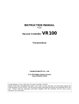
2.6.4 Solenoid Outputs and Ambient Temperature
If only one solenoid output is powered at a time, then there are no restrictions and the single solenoid current
may reach the maximum current according to the Electrical Specifications over the whole temperature range.
But the total solenoid current of simultaneously powered solenoids depends on the ambient temperature.
Exceeding this current limit will trip the overcurrent protection circuit, the SD6 falls into the failure state and
blocks all function.
Solenoids can be powered simultaneously, i.e.on the amplifier in operating mode 4, or with inverted solenoid
outputs.
If solenoids are powered with more voltage than their nominal voltage and are so over-energized, then at fast
switching-on, the overcurrent protection may trip and the SD6 may fall into failure state and block all function.
The following graphics shows the maximum allowed total solenoid current over ambient temperature when both
solenoids are powered at the same time.
SD6: Derating of Total Solenoid Current when both Solenoid Outputs activated simultaneously
2000
2200
2400
2600
2800
3000
3200
3400
3600
3800
4000
4200
4400
4600
4800
5000
20 25 30 35 40 45 50 55 60 65 70
Ambient Temperature [°C]
Total Solenoid Current [mA]
Derating for 12V SD6
Derating for 24V SD6
5

Wandfluh AG
Postfach
CH-3714 Frutigen
Tel: +41 33 672 72 72
Fax: +41 33 672 72 12
Email: [email protected]
Internet: www.wandfluh.com
Page 8
Edition 12 14
SD636bae.pdf
Operating instructions to Enhanced Controller module SD6
2.7 Block diagram
Driving through the analogue interface
LED red
LED yellow
DC
DC
X1-5
X1-6
X1-7
Supply voltage
Stailized
output voltage
+
0 VDC
LED
green
X1-9
X1-10
-
+
Analogue input 1
X1-11
X1-12
-
+
Analogue input 2
X1-1
Digital input 1
X1-2
Digital input 2
Digital ground
Solenoid A
U
I
X1-15
X1-16
Solenoid B
U
I
X1-13
X1-14
Digital output 1
X1-3
Digital output 2
X1-4
Microcontroller
FEPROM
RAM
EEPROM
PWM
A/D
PWM
A/D
+
-
+
-
A
D
Digital output 3
Digital output 4
-
Analogue input 3
-
+
Analogue input 4
+
-
+
-
A
D
10-Bit
16-Bit
Stailized
output voltage
Ref
SPI
Digital input 3
Digital input 4
Digital input 5
Digital input 6
Digital input 7
Digital input 8
SPI
D
A
12-Bit
Analogue output
X2-1
X2-2
X2-4
USBX2-3
+
-
Ref
Output +24VDC
Output +5VDC
Clock output +
Clock output -
Data input +
Data input -
Sensor-ground
Analogue ground
X1-8
Analog ground
X1-17
X1-18
X1-19
X1-20
X1-21
X1-22
X1-29
X1-31
X1-25
X1-26
X1-27
X1-28
+
X1-32
X1-30
X1-23
X1-24
X3-2
X3-1
X3-6
X3-5
X3-8
X3-9
X3-7

Wandfluh AG
Postfach
CH-3714 Frutigen
Tel: +41 33 672 72 72
Fax: +41 33 672 72 12
Email: [email protected]
Internet: www.wandfluh.com
Page 9
Edition 12 14
SD636bae.pdf
Operating instructions to Enhanced Controller module SD6
3 Safety rules
3.1 Installation / Commissioning / Parameterisation
· These operating instructions have to be carefully studied beforehand and the instructions are to be complied
with.
· Prior to the installation, all power supply voltages and any other energy sources have to be disconnected.
· The installation/assembly must only be carried out by specialist personnel with electrical knowledge.
· Take into account precautionary measures concerning components on the module, which are subject to
damage as a result of electrostatic discharge.
· Wrong manipulations by the personnel cannot be prevented by the SD6-Electronics.
· Before the switching on of the supply voltage, the fuse protection, the correct wiring and the conformity of the
power supply voltage with the permissible supply voltage range have to be verified.
· The SD6-Electronics monitors the working conditions within the electronics and
within the installation. Uncontrolled movements or force changes caused by
unforeseen errors of the SD6-Electronics cannot be prevented in any case.
· Danger for persons has to be avoided by installing an emergency stop device which
cuts off the power to the system.

Wandfluh AG
Postfach
CH-3714 Frutigen
Tel: +41 33 672 72 72
Fax: +41 33 672 72 12
Email: [email protected]
Internet: www.wandfluh.com
Page 10
Edition 12 14
SD636bae.pdf
Operating instructions to Enhanced Controller module SD6
4 Construction and Function
Refer to section "Block diagram" .
4.1 Introduction
· All inputs and outputs have to be contacted through the terminal screw block
· At the device front panel, there is a USB interface, through which the parameterisation and the diagnostics
can be made by using the PC-Parameterisation software PASO DSV/SD6
· In the factory, the SD6-Electronics are adjusted with the default values. The adjustment to the valves being
used, has to performed by the user.
4.2 Description of the Function
With the SD6-Electronics, it is possible to build different closed circuit controls. Apart from controls for pressure,
volume flow or position, also pQ- and alternating controls can be implemented. They can optionally be adjusted
in the form of a controller mode. In addition, an amplifier part is integrated, with which the connected valve resp.
its solenoid is directly driven.
The command value is conducted to the controller as an electric signal, a sensor records the feedback value,
this signal is also conducted to the controller. In correspondence with the control difference (command value -
feedback value), a control signal (solenoid current) is output to the valve.
By means of the scaling of the command value and feedback value, all further inputs can be made in the
required, resp., selectable physical unit (e.g., bar or mm, etc.). When the command value has been reached,
then the SD6 is capable of outputting a digital signal (optionally an „Error“- or „Target window reached “ - signal).
The SD6 - controller has a command value generator, with which the up - and down ramp of the internal
command value can be predefined. The controller is designed as a PID - controller. The control characteristics
as a result of this can be equalised and adapted to the control circuit. Furthermore, it is also possible to
switch-off the control system completely for testing - and adjusting purposes. The SD6 in this case operates in
correspondence with normal amplifier electronics.
Furthermore the controller module “SD6” comprises digital inputs for the enabling, for controlling the manual
operation and for the profile generator as well as digital outputs, which output the conditions „Error“ or „Target
window reached “.
Changed parameters can be saved in a non-volatile memory, so that following a renewed switching-on of the
control system they are still available once again.
The SD6 - electronics in addition have a signal recording function. By means of PASO, this makes possible a
recording of different system signals, such as, e.g., command value / feedback value, control difference,
solenoid currents, etc., which are able to be graphically displayed on a common time axis.
The manual operating mode makes available commands such as Forwards, Backwards, Rapid Speed and
Creep Speed. With this it is possible to put the connected hydraulics into operation without a super-ordinate
control system.
4.3 Characteristic optimisation
The SD6 electronics are provided with a possibility to optimise the characteristic “Preset value input – solenoid
current output”. The user is able to create a characteristic (e.g. a linearised characteristic) which matches his
own application. The characteristic optimisation can be turned on or off (refer to “Parameters_Valves” on page
21). This setting is available only with a SD6-electronics with software version higher than 1.1.1.6 and PASO with
software version higher than 1.5.0.9!
8

Wandfluh AG
Postfach
CH-3714 Frutigen
Tel: +41 33 672 72 72
Fax: +41 33 672 72 12
Email: [email protected]
Internet: www.wandfluh.com
Page 11
Edition 12 14
SD636bae.pdf
Operating instructions to Enhanced Controller module SD6
4.4 SD6 State machine
In the following, with the help of a status diagram it is described, how the start-up of the SD6-Electronics takes
place and which statuses are reached when and how.
The following table describes the possible statuses and what is done in these statuses:
Status
Description
Disabled
· The SD6-Electronics are disabled, no solenoid current will be active
· In this state, with the command "Local operation" resp. "PASO operation"
(refer to section "Commands_Local Operating / PASO" ) the operating
mode can be set.
Active
· The SD6-Electronics are enabled
· The SD6-Electronics can be operated according to the selected operating
mode
· Changing the operating mode is not possible
The following table describes the transitions from one status to the next one:
Transition
Description
TR_0
Switching-on the supply voltage
TR_1
Enable
This is made in the operating mode "Local" through the digital input "Enable
control" (refer to section "Digital inputs" ) and in the operating mode
"Remote PASO" through the command "Enable" (refer to section
"Commands_Disable / Enable" ).
TR_2
Disable
This is made in the operating mode "Local" through the digital input "Enable
control" (refer to section "Digital inputs" ) and in the operating mode
"Remote PASO" through the command "Enable" (refer to section
"Commands_Disable / Enable" ).
72
13
72
13
72

Wandfluh AG
Postfach
CH-3714 Frutigen
Tel: +41 33 672 72 72
Fax: +41 33 672 72 12
Email: [email protected]
Internet: www.wandfluh.com
Page 12
Edition 12 14
SD636bae.pdf
Operating instructions to Enhanced Controller module SD6
4.5 Operating mode
The SD6-Electronics have 2 operating modes. The following table describes, what can be done in the different
operating modes and how they can be activated:
Operating mode
Activating with
Description
Local
Menu point "Commands_Local Operating"
Operating via analogue and digital inputs
on the SD6-Electronics
Remote PASO
Menu point "Commands_PASO Operating
Operating direct with the PASO
The current operating mode is displayed in the status line (refer to section "Starting of PASO DSV/SD6" ).
For more information about the operating mode "Local" and "Remote", please refer to section
"Commands_Local Operating / PASO" .
4.6 Analogue inputs
· The applied analogue signal is digitised in the 10Bit A/D converter at analogue inputs 1 and 2 resp. in the 16Bit
A/D converter at analogue inputs 3 or 4.
Attention: By the input range 4 ... 20mA, the resolution is < 10Bit resp. < 16Bit!
· Differential inputs
All analogue inputs are differential inputs. Differential inputs are used if the ground potential of the external
command value generator does not agree with the ground on the SD6-Electronics.
If the differential input is intended to use like an analogue input against ground, the - (minus) connection of the
differential input must be connected to the ground of the SD6-Electronics. In this case please attend that the
solenoid current can cause a voltage drop between the SD6-Electronics and the power supply. It is
recommended to connect the - (minus) connection as near as possible to the power supply.
SD6-Type
Analogue input 1
(10-bit resolution)
Analogue input 2
(10-bit resolution)
Analogue input 3
(16-bit resolution)
Analogue input 4
(16-bit resolution)
SD6362DX4-BX
0...10VDC
0...±10VDC
(only with 2-sol
control modes)
0...20mA, 4...20mA
0...10VDC
0...±10VDC
(only with 2-sol
control modes)
0...20mA, 4...20mA
SD6362DX5-BX
0...10VDC
0...±10VDC
(only with 2-sol
control modes)
0...10VDC
0...±10VDC **
(only with 2-sol
control modes)
0...10VDC
0...±10VDC
(only with 2-sol
control modes)
0...10VDC
0...±10VDC
(only with 2-sol
control modes)
SD6362DX6-BX
0...20mA, 4...20mA
0...20mA, 4...20mA
0...20mA, 4...20mA
0...20mA, 4...20mA
SD6362DX7-BX
0...10VDC
0...±10VDC
(only with 2-sol
control modes)
0...10VDC
0...±10VDC **
(only with 2-sol
control modes)
0...20mA, 4...20mA
0...20mA, 4...20mA
SD6362DX8-BX
0...20mA, 4...20mA
0...20mA, 4...20mA
0...10VDC
0...±10VDC
(only with 2-sol
control modes)
0...10VDC
0...±10VDC
(only with 2-sol
control modes)
**) 0...+10VDC on SD6 with Profibus
86
72

Wandfluh AG
Postfach
CH-3714 Frutigen
Tel: +41 33 672 72 72
Fax: +41 33 672 72 12
Email: [email protected]
Internet: www.wandfluh.com
Page 13
Edition 12 14
SD636bae.pdf
Operating instructions to Enhanced Controller module SD6
4.7 Cablebreak detection
The analogue inputs with input signal range of 4...20mA can be detected for a cablebreak. If a cablebreak is
present (input signal less than 3mA), the corresponding solenoid outputs will be blocked and the output "Error"
will be active. The following conditions had to be performed:
· The input signal must be a current value 4 ... 20mA
· The parameter "Cablebreak" must be on "On"
Attention: Until a cablebreak will be detected, a time delay of about 100ms will pass. During this time, the
cylinder can make unintentional movements or unintentional force changes.
4.8 Digital inputs
· Digital input 1 " Enable control"
The digital input is active-high (refer to section "Electrical specifications" ).
If this input is set, the SD6-Electronics are enabled. Without this enable, no solenoid current will be output.
This digital input can be set also through the parameterisation software PASO DSV/SD6 (refer to section
"Configuration_Digital I/O" ).
· Digital input 2 "Automatic / Manual operation"
At manual operation (digital input low) the command value is being generated by digital inputs 3...5. For this
two velocities are available in both directions.
At automatic operation (digital input high) the command value is being generated by the profile generator or
read from an analog input, depending on the state of the digital inputs 3...8.
To switch between manual and automatic operation, the SD6 has to be disabled by deactivating digital input
1.
· Digital input 3 "Manual forward" or "Profile / Sequence"
Manual operation: When the digital input is activated the command value will be incremented. The velocity
depends on digital input 5 "Rapid speed / Creep speed".
Automatic operation: Choice between running through a complete profile (digital input high) or an individual
sequence (digital input low).
· Digital input 4 "Manual reverse" or "Start"
Manual operation: When the digital input is activated the command value will be decremented. The velocity
depends on digital input 5 "Rapid speed / Creep speed".
Automatic operation: Depending on digital input 3 "Profile / Sequence" the running through of the complete
profile or of the next sequence only is started.
· Digital input 5 "Rapid speed / Creep speed" or "Stop"
Manual operation: Changeover between rapid speed (digital input high) and creep speed (digital input low).
Automatic operation: As long as the digital input is high the axis can move. As soon as the digital input
becomes low the movement is stopped (set-point value = feedback value).
· Digital input 6...8 "Profile selection"
These digital inputs only take effect in automatic operation. Profiles can only be used in closed loop control
modes (an exception is the pQ-control mode, where no profiles can be used). How to select the profiles is
shown in the table below. If profile 0 is selected the command value will be read from one of the analogue
input. A detailed description of the profiles is located in the section "Profile-Menu"
5
65
37

Wandfluh AG
Postfach
CH-3714 Frutigen
Tel: +41 33 672 72 72
Fax: +41 33 672 72 12
Email: [email protected]
Internet: www.wandfluh.com
Page 14
Edition 12 14
SD636bae.pdf
Operating instructions to Enhanced Controller module SD6
Digital input 6
Digital input 7
Digital input 8
Profile
0
0
0
* 0 (analogue command value)
1
0
0
1
0
1
0
2
1
1
0
3
0
0
1
4
1
0
1
5
0
1
1
6
1
1
1
7
* with control mode "Alternating control (2-sol)" the analogue command value will not read if profile selection
is 0. In this case, the command value will be set to the actual value (= axis remains controlled at the actual
position). Should be used an analogue command value, the corresponding signal type must be selected
(refer to section "Configuration_Signal Scaling ").
4.9 Input for digital sensor
This input makes it possible to connect digital sensors with SSI- or Start/Stop-Interface.
SSI-Interface
SSI-Interface according RS-422 standard with a baudrate of 300kHz.
Start/Stop-Interface
This Interface supports sensors with a Start/Stop-Interface as they are available e.g. from Balluff or MTS.
53

Wandfluh AG
Postfach
CH-3714 Frutigen
Tel: +41 33 672 72 72
Fax: +41 33 672 72 12
Email: [email protected]
Internet: www.wandfluh.com
Page 15
Edition 12 14
SD636bae.pdf
Operating instructions to Enhanced Controller module SD6
4.10 Outputs
· Proportional solenoid outputs A and B
The max. 2 solenoid outputs have a current output with 1000 Hz Pulse-Width-Modulation with superimposed
dither.
· Analog output
The analog output can be assigned to the following signals via the PASO DSV/SD6 (depending on the control
mode, different signals are available):
- command value for the solenoid driver
- scaled command value
- scaled feedback value (only with closed loop control modes)
- scaled control deviation (only with closed loop control modes)
The signal at the analog output can be used for driving a valve with integrated electronics which has a voltage
interface. The output level can be adjusted (refer to section "Configuration_Analog output" ).
· Digital outputs
The following digital outputs are available:
- Digital outut 1 "Error"
- Digital outut 2 "Solenoid B active", "Inside target window / End of Seq"
- Digital outut 3 "Trailing error"
- Digital outut 4 "Profile End reached"
The digital output can be configured by the PASO DSV/SD6 Software (refer to section "Configuration_Digital
I/O" ).
4.11 Controller Modes
The SD6-Electronics provide the following controller modes:
· Controller mode 3 "Pressure/flow valve open loop"
Control of a pressure relief-, pressure reducing- or flow control valve in open loop (without feedback signal).
The number of solenoids, which are activated, depends on the selected mode of operation (refer to section
"Mode of operation" ).
This mode of operation corresponds to the "Device Control Mode = 3" of the fieldbus device profile Fluid
Power Technology.
65
65
52

Wandfluh AG
Postfach
CH-3714 Frutigen
Tel: +41 33 672 72 72
Fax: +41 33 672 72 12
Email: [email protected]
Internet: www.wandfluh.com
Page 16
Edition 12 14
SD636bae.pdf
Operating instructions to Enhanced Controller module SD6
· Controller mode 4 "Pressure/flow valve closed loop (1-sol)"
Control of a 1-solenoid pressure relief-, pressure reducing- or flow control valve in closed loop (with feedback
signal). It can only be activated one solenoid (correspond to solenoid driver 1).
In this controller mode, the parameter "Mode of operation" has no meaning (refer to section "Mode of
Operation" ).
This mode of operation corresponds to the "Device Control Mode = 4" of the fieldbus device profile Fluid
Power Technology.
Example Application:
Pressure Control: with one proportional pressure relief valve, the pressure p is held constant to the command
pressure value w.
Example Application: Flow Control: with one proportional throttle valve, the flow Q is held constant to the flow
command value w.
· Controller mode 6 "Position open loop"
Control of a spool valve in open loop (without feedback signal).
The number of solenoids, which are activated, depends on the selected mode of operation (refer to section
"Mode of operation" ).
This mode of operation corresponds to the "Device Control Mode = 6" of the fieldbus device profile Fluid
Power Technology.
52
52

Wandfluh AG
Postfach
CH-3714 Frutigen
Tel: +41 33 672 72 72
Fax: +41 33 672 72 12
Email: [email protected]
Internet: www.wandfluh.com
Page 17
Edition 12 14
SD636bae.pdf
Operating instructions to Enhanced Controller module SD6
· Controller mode 7 "Speed control closed loop (2-sol)"
Control of a 2-solenoid pressure relief-, pressure reducing- or flow control valve in closed loop (with feedback
signal). It can be activated two solenoids.
In this controller mode, the parameter "Mode of operation" has no meaning (refer to section "Mode of
Operation" ).
This mode of operation corresponds to the "Device Control Mode = 7" of the fieldbus device profile Fluid
Power Technology.
· Controller mode 9 "Position closed loop"
Control of a 2-solenoid spool valve in closed loop (with feedback signal). It can be activated two solenoids.
In this controller mode, the parameter "Mode of operation" has no meaning (refer to section "Mode of
Operation" ).
This mode of operation corresponds to the "Device Control Mode = 9" of the fieldbus device profile Fluid
Power Technology.
Example application: with a 4/3-proportional-spool valve, the axis position is held constant to the command
position value w..
· Controller mode –5 "Pressure control closed loop (2-sol)"
52
52

Wandfluh AG
Postfach
CH-3714 Frutigen
Tel: +41 33 672 72 72
Fax: +41 33 672 72 12
Email: [email protected]
Internet: www.wandfluh.com
Page 18
Edition 12 14
SD636bae.pdf
Operating instructions to Enhanced Controller module SD6
Control of two 1-solenoid throttle valves in closed loop (with feedback signal) as a pressure reducing system.
One throttel valve is the loading valve, the other throttel valve is the unloading valve. The loading valve
corresponds to solenoid driver 1, the unloading valve to the solenoid driver 2.
In this controller mode, the parameter "Mode of operation" has no meaning (refer to section "Mode of
Operation" ).
This controller mode is a WANDFLUH specific controller mode and does not correspond to the fieldbus
device profile Fluid Power Technology.
This setting is available only with a SD6-electronics with software version > 1.1.1.6 and PASO with software
version > 1.5.0.9!
· Controller mode –9 "pQ control (2-sol)"
Driving of a direction control valve in open loop control circuit (without feedback signal) with monitoring of a
predefined pressure (with feedback signal).
There is a Q and a p command value. With the Q command value, the cylinder can move in open loop in both
directions. The p command value defines the maximum allowed pressure. If this pressure is exceeded, the
controller reduces the output signal to the valve. In this case the preset pressure is not exceeded. A rear
dodge (cylinder moves backward) is possible. The p feedback value can be either an absolute signal (V or
mA) from a pressure or force sensor or can be built as a differential signal from two pressure or force sensors
(V or mA).
With this controller mode, the choice of the proportional valve has a high influence on the system behavior.
More details about it are available from factory.
Example application: with a 4/3-proportional-spool valve, the axis will move in open loop (without feedback
signal). Simultaneously the pressure is monitored (measured with the pressure sensor).
52

Wandfluh AG
Postfach
CH-3714 Frutigen
Tel: +41 33 672 72 72
Fax: +41 33 672 72 12
Email: [email protected]
Internet: www.wandfluh.com
Page 19
Edition 12 14
SD636bae.pdf
Operating instructions to Enhanced Controller module SD6
This setting is available only with a SD6-electronics with software version higher than 1.1.3.0 and PASO with
software version higher than 1.5.1.2!
· Controller mode –10 "Alternating control (2-sol)"
Driving of a direction control valve in closed loop control circuit (with feedback value return) with monitoring of
a predefined pressure (with feedback value return).
There is a pos and a p command value. With the pos command value, the cylinder can move in closed loop
in both directions. The p command value defines the maximum allowed pressure. If this pressure is
exceeded, the position controller is swichted off and the controller reduces the output signal to the valve. In
this case the preset pressure is not exceeded. If the actual pressure is smaller than the p command value,
the position controller is switched on. A rear dodge (cylinder moves backward) is possible. The p feedback
value can be either an absolute signal (V or mA) from a pressure or force sensor or can be built as a
differential signal from two pressure or force sensors (V or mA).
With this controller mode, the choice of the proportional valve has a high influence on the system behavior.
More details about it are available from factory.
Example application: with a 4/3-proportional-spool valve, the axis position is held constant to the command
position value w. Simultaneously the pressure is monitored (measured with the pressure sensor).

Wandfluh AG
Postfach
CH-3714 Frutigen
Tel: +41 33 672 72 72
Fax: +41 33 672 72 12
Email: [email protected]
Internet: www.wandfluh.com
Page 20
Edition 12 14
SD636bae.pdf
Operating instructions to Enhanced Controller module SD6
This setting is available only with a SD6-electronics with software version higher than 1.1.3.0 and PASO with
software version higher than 1.5.1.2!
/