Page is loading ...

control unit
Mindy A500
Instructions and warnings for the fitter
Istruzioni ed avvertenze per l’installatore
Instructions et recommandations pour l’installateur
Anweisungen und Hinweise für den Installateur
Instrucciones y advertencias para el instalador
Instrukcje i uwagi dla instalatora
Aanwijzingen en aanbevelingen voor de installateur

2
6 Operating modes
7 Programming
7.1 Programmable functions
7.2 Description of functions
8 Using 2 central units on opposite wings
9 Accessories
10 Maintenance
10.1 Environmental protection measures
10.2 Technical specifications
Mindy A500
Introduction:
This manual has been especially written for use by technical personnel
qualified to carry out installation. No information given in this manual can
be considered as being of interest to end users! This manual is enclosed
with control unit A500 and may not be used for different products!
Important notice:
The A500 control unit has been designed to control an electromechani-
cal actuator for automating gates or doors. Any other use is considered
improper and is consequently forbidden by current laws.
May we remind you that the automation system you are about to
install is classified as “building a machine” and therefore enters the field
of application of European directive 89/392 EEC (machine directive).
This directive includes the following prescriptions:
-Only trained and qualified personnel should install the equipment
-The installer must first perform the “risk analysis” of the machine
-The equipment must be correctly and professionally installed in compli-
ance with all relevant standards.
-After installation, the machine owner must be issued with the “declara-
tion of conformity”.
This product may only be installed and serviced by qualified personnel,
therefore, in compliance with current laws, standards or directives.
When designing and producing its products, Nice observes all applica-
ble standards (please see the attached declaration of conformity) but it
is of paramount importance that installers continue to strictly observe the
same standards when installing the system.
Unqualified personnel or those who are unaware of the standards
applicable to the “automatic gates and doors” category may not install
systems under any circumstances
Whoever ignores such standards will be held responsible for any
damage caused by the system!
Do not install the unit before you have read all the instructions thor-
oughly!
Particular warnings concerning the suitable use of this product in relation
to the 73/23/EEC “Low Voltage” Directive and subsequent modification
93/68/EEC:
- This product responds to the provisions foreseen by the “Low Voltage”
Directive if used in the configurations foreseen in this instructions manu-
al and in combination with the articles present in the Nice S.p.a. product
catalogue. If the product is not used in configurations or is used with oth-
er products that have not been foreseen, the requirements may not be
guaranteed; the use of the product is prohibited in these situation until
the correspondence with the requirements foreseen by the directive
have been verified by installers.
Particular warnings concerning the suitable use of this product in relation
to the 89/336/EEC “Electromagnetic Compatibility” Directive and subse-
quent modifications 92/31/EEC and 93/68/EEC:
- This product has been subjected to tests regarding the electromag-
netic compatibility in the most critical of use conditions, in the configu-
rations foreseen in this instructions manual and in combination with arti-
cles present in the Nice S.p.A. product catalogue. The electromagnetic
compatibility may not be guaranteed if used in configurations or with
other products that have not been foreseen the use of the product is
prohibited in these situations until the correspondence to the require-
ments foreseen by the directive have been verified by those performing
the installation.
!
!
!
Index:
1 Description of the product
2 Installation instructions
2.1 Input voltage selection
2.2 Wiring diagram
2.3 Description of connections
2.4 Notes about connections
3 Testing
4 Adjustments
5 Obstacle adjustment system

GB
3
R
Q
S
POMN
AP
CH
L
H
I
G
F
T
A
U
BC
D
E
TLM
F2= 0.5 A
"PIU"
OK
1
TPTL F
F1= 0.5 A
COM
RADIO
400
230
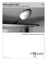
A Mains power switch 230 / 400 V
B Overload cut-out
C Power supply transformer
D Control unit power fuse (500mA)
E Adjustment trimmer
F Radio terminal board
G Function selection dip-switch
H OK LED
I Connector for Door controls
L Input status LED’s
M Input/output control terminal board
N Limit switch input terminal board
O Phototest output terminal board
P Motor power output
Q Flashing light output
R Flashing light fuse (500mA)
S Motor manoeuvre remote control switches
T Flashing light activation relay
U Brake activation relay
1) Description of the product:
This unit controls an alternate current three-phase or single-phase
motor at 230V or 400V for automatic doors and gates. It features
obstacle detectors (anti-crush devices) and a braking system which
reduces inertia during the stopping phase. It also features a series of
functions that can be selected by dip-switches (mini-switches) and
adjustments performed by trimmers.
The control unit features input status LED’s located near such inputs,
while another LED near the microprocessor indicates that the internal
logic works correctly.
2) Installation:
Before starting to install the unit, check the sturdiness and
mechanical consistency of the gate and make sure safety stops and
minimum distances are respected. Carry out a careful and thorough
“risk analysis” of the automatic system, evaluate the safety devices to
be installed with particular care and always fit an emergency stop
device.
Make absolutely sure that the mechanical stops are of the right shape
and strong enough to stop the motor in all conditions; they must be
able to absorb all the kinetic energy accumulated during movement
without deforming in the slightest.
Do not install the motor without the “Mechanical travel
stops”
Besides the standards referring to electrical installations in general,
automatic machines, doors and gates, we also supply some specific
notes that will make the whole system even safer and more reliable:
-The power line leading to the unit must always be protected by a
circuit breaker or three 5A-fuses; a differential switch is
recommended but not essential if there is already one up-line from
the system.
-Power the unit using a 5 x 1.5 mm
2
cable (3 phases + neutral +
earth); should the distance between the unit and the earth
connection exceed 30 m, install an earth plate near the unit.
-Use wires with a minimum cross section of 0.25 mm
2
to connect low
voltage safety circuits.
Use shielded wire if the length exceeds 30 m and connect the earth
braid only on the unit side.
-Only use cables (various individually insulated wires plus an
additional general insulation); never use single wires even if they are
protected inside ducts.
-It is absolutely forbidden to connect cables in buried boxes even if
they are completely watertight.
Make sure you have all the necessary materials suitable for this use.
The unit must be installed correctly in order to guarantee an adequate
level of safety and protection against atmospheric agents. Please
bear in mind that the unit contains particularly delicate live parts and
electronic components.
The unit is supplied in a container which, if appropriately installed, will
guarantee a protection level of IP55 (in compliance with CEI 70-1 and
IEC 529) which means it is also suitable for outdoor installation.
However, several simple but important rules must be followed:
-Install the unit on a permanent surface, perfectly flat and adequately
protected against knocks, making sure that the unit bottom is at least
40 cm from the ground.
-Install cable or pipe leads only at the bottom of the unit; for no
reason whatsoever must the side and top walls be perforated. The
cables must only enter the unit from the bottom!
!
1

4
44
AERIAL
19
P.P.
M
PHOTO
Max 200 mA
24 Vac
SCA
COM (24V)
24 Vac Max 200mA
FCC
COM
FCA
PHOTOTEST
LAMP.
230 Vac 40W
400 V
U
W
V
1
2
4
3
5
6
7
ALT
12
9
8
11
10
15
13
14
18
17
16
"PIU"
OK
CH
AP
20
21
41
43
42
2° Ch RADIO
3
400
COM
RTS
400 V
F2= 0,5 A
TLM
TPTL F
+
-
+
-
+
-
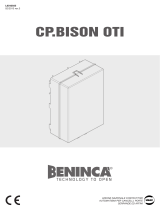
2.2) Wiring diagram:
Under no circumstances, while wiring or plugging in the various
cards, may the unit be electrically powered, to safeguard the
operator and avoid damaging the components.
Please also bear in mind that if the inputs of the NC (Normally Closed)
contacts are not used they should be jumpered with the “common”
terminal; if there is more than one contact, then they should be
connected in SERIES. If the inputs of the NO (Normally Open)
contacts are not used they should be left free and if there is more
than one contact then they should be connected in PARALLEL. The
contacts must be of the mechanical type and potential-free; no
connections are allowed, such as those defined as "PNP", "NPN",
"Open Collector" etc..
Before making connections, check that the selection corresponds to
the available input voltage.
Any errors during the selection can seriously damage the
components of the control unit!
The drawing in figure shows the connections of the control unit with
three-phase 400V power supply.
To connect the control unit with 230 Volt single-phase or three-phase
power inputs, please refer to the drawings in figure 3a-3b.
N.B.:
Only qualified and expert personnel may carry out installation and subsequent maintenance operations following the rules of good workmanship and
in compliance with EEC directive 89/392 (Machine Directive) and, in particular, EN 60204 (Electrical wiring of machines).
2.1) Input voltage selection:
The power unit can either work with three-phase or single-phase power supply (see wiring diagrams) with voltages of
400V or 230V. Select the input voltage by fitting in a jumper between the “COM” terminal and the “230” terminal or the
“400” terminal as shown in figure.
2
COM
230
400

GB
5
230
COM
230 V Single-phase
LN
230 V
AP
COM
3
1
2
F2= 0.5 A
CH
6
4
5
7
M
230 Vac 40W
400
COM
RTS
230 V Three-phase
230 V
V
U
3
2
1
F2= 0.5 A
W
6
5
4
7
M
230 Vac 40W
400
COM
400 V Three-phase
RST
400 V
V
U
1
2
3
W
6
4
5
7
F2= 0.5 A
M
230 Vac 40W
2.3) Descriptions of connections:
All the connections are made by means of special terminals located
on the lower side of the electronic card. Only the power input line
should enter the upper part, directly connected to the overload cut-
out terminals.
To connect the earth circuit to the control unit and motor, use
terminals 6-7 wherever possible.
If the control unit is powered by a single-phase system just two wires
must be connected to the first two terminals to the left of the overload
cut-out (the third terminal being unused). Connect the single-phase
motor and relative condenser as shown in figure 3a.
Take care when selecting 400V or 230V input voltage.
A brief description of the possible connections of the control unit outputs follows.
1-2 : Flashing light = Connection to 220 Vac max. 40W flashing light
3-4-5 : Motor = Line to motor 230Vac / 400Vac
6-7 : Earth = Control unit and motor earth connection
8-9 : Phototest = 24 Vac output to power photoelectric cell transmitters (Max. 200mA)
10 : Open limit switch = OPEN limit switch input
11 : Common = Common for limit switch inputs
12 : Close limit switch = CLOSE limit switch input
13-14 : 24 Vac = 24 Vac output to accessories Max. 200mA (400mA if phototest is not used)
15 : Common = Common for all inputs
16 : Gate open indicator = Max. 24 Vac output for gate open indicator 2W
17 : Stop = Input with STOP function (Emergency, shutdown or extreme safety)
18 : Photocell = Input for safety devices (photoelectric cells, pneumatic edges)
19 : Step-by-step = Input for cyclic functioning (OPEN STOP CLOSE STOP)
20 : Open = Input for opening
21 : Close = Input for closing
41-42 : 2° Radio Ch = Output for the second radio receiver channel, if any
43-44 : Aerial = Input for the radio receiver aerial
There are two additional slots on the unit card for optional cards:
RADIO =Slot for NICE radio receivers
PIU =Slot for “PIU” expansion card with extra functions
We recommend waiting until installation is complete before plugging in the optional RADIO or PIU cards.
The optional cards are not essential for system operation and, if used, they make troubleshooting more complicated.
Connecting the control unit with 230V single-phase power supply
Connecting the control unit with 230V three-phase power supply
Connecting the control unit with 400V three-phase power supply
3b
3c
3a

6
2.4) Notes about connections:
Most connections are simple; many of them are direct connections to
a single user point or contact but others are a little more complicated.
A particular description should be made of the “Phototest” output;
this is the best possible solution in terms of reliability as regards safety
devices and puts the control unit and safety photocells in “category 2”
according to UNI EN 954-1 standard (ed. 12/1998).
Before every manoeuvre is begun, the relative safety devices are
checked and only if everything is in order will the manoeuvre start.
Should the test be unsuccessful (photocells blinded by the sun, short
circuited cables, etc.) the failure is identified and the manoeuvre is not
carried out.
This can only be achieved by using a certain configuration in the safety
device connections that require the photocell transmitter power input
to be connected to terminals 8-9 while the receiver power input should
be derived from the accessories output (terminals 13-14).
When movement is required, it is first checked that all the receivers
involved in the movement give their consent, then the phototest output
is turned off after which it is checked that all the receivers signal the fact
by removing their consent; the phototest output is finally reactivated
and the consent of all the receivers is verified once more.
Synchronism should always be activated on the two transmitters by
cutting the jumpers; this is the only way of ensuring that the two pairs
of photoelectric cells do not interfere with one another.
Check the instructions in the photocell manual regarding
synchronised functioning.
If a PHOTO input is not used (e.g.: PHOTO2) and the phototest
function is required, jumper the unused input with phototest output
terminal n°9.
TX
PHOTO 2
(PIU card)
8
TX
PHOTO
9
RX
RX
14
13
15
PIU (10)
18
Once the motor and various accessories have been connected you
can now check all the connections and test the installation.
ATTENTION: the following operations entail working on live
circuits; most of these run on extra-low safety voltage so they
are not dangerous but some are powered by mains voltage
which means they are HIGHLY DANGEROUS! Pay the greatest
of attention to what you are doing and NEVER WORK ALONE!
Work on the control unit should be started in the “manual mode” and
with all the functions deactivated (dip-switches OFF); in all cases,
when working in the manual mode and the control key is released,
the motor will stop immediately. Also check that all the adjustment
trimmers are at a minimum (turned fully anti-clockwise); only the
“FORCE” trimmer can be positioned on maximum.
A) Unlock the gate and take it halfway the run and then lock it;
now it is free to move in either the opening or closing direction.
B) Make sure you have selected the correct input voltage on the
terminal board to the left of the overload cut-out.
C) Power the unit and check that voltage between terminals 13-
14 and 8-9 is 24 Vac.
As soon as the unit is powered the indicator lights (LED’s) on the
active inputs should turn on and shortly after the "OK" LED should
start flashing regularly. If none of these events occur, turn power off
immediately and check the connections more carefully.
The “OK” LED in the centre of the card has the job of signalling the
state of the internal logic: regular flashing at 1 second intervals means
that the internal microprocessor is active and waiting for commands.
When the microprocessor recognises a variation in the state of an
input (whether it is a command or function dip-switch input) it
generates a rapid double flash even if the variation does not have any
immediate effect. Extremely rapid flashing for 3 seconds means that
the control unit has just been powered or is performing internal
testing, lastly, irregular flashing means that the test has been
unsuccessful and that a fault has occurred.
D) Now check that the NC-contact inputs LED’s are on (all safety
devices active) and that the NO-contact inputs LED’s are off
(no command present); if this is not the case, check the
connections of the various devices and make sure they are in
good working order.
E) Check that all the safety devices of the unit are in proper
working order (emergency stop, photocells, pneumatic edges,
etc.); each time they cut in, the relative STOP or PHOTO LED
should turn off.
F) Check the limit switches are connected properly; move the
gate and check that once the required point is reached the
relative limit switch cuts in and switches off the relative LED on
the control unit.
G) Now make sure that movement is in the right direction, that is,
check that the movement set on the unit corresponds to that
of the wings. This check is of paramount importance. If the
direction is wrong, in some cases (in the semiautomatic mode,
for instance) the gate might appear to be working properly. In
fact, the OPEN cycle is similar to the CLOSE cycle but with one
basic difference. The safety devices are ignored in the closing
manoeuvre, which is normally the most dangerous, and they
will trigger in the opening manoeuvre causing the gate to close
up against the obstacle with disastrous results!
To see whether the direction of rotation is correct, give a short
pulse to the Step-by-Step input; the first manoeuvre the unit
will carry out after being powered is always an OPEN one, so
simply verify that the gate starts opening; if this movement is
incorrect, proceed as follows:
1 – Turn the power off
3) Testing:
!
4

GB
7
2 – For the three-phase motor, exchange 2 of the 3 motor
connections. For the single-phase motor, exchange the
“OPEN” and “CLOSE” motor connections.
Once this has been done, check if the direction of rotation is now
correct by repeating the procedure described in point “G”.
H) Perform a complete movement of the actuator; we
recommend to always work in the manual mode with all
functions deactivated. Use the command inputs to move the
gate until it reaches the open point; if everything works
normally, continue with the closing manoeuvre and move the
gate until it reaches the stop point.
I) Carry out several open and close manoeuvres in order to
evaluate any defects in the mechanical structure of the
automation system and pinpoint any specific points of friction.
L) Test the PHOTOCELL safety devices triggering; they have no
effect in the opening manoeuvre but they will stop movement
during the closing manoeuvre. If the PIU card is plugged in,
test the PHOTOCELL 2 input: it has no effect in the closing
manoeuvre but it will stop movement during the opening
manoeuvre. The devices connected to the STOP input work
during both the opening and closing manoeuvres and stop
movement in each case.
The control unit can be adjusted in 3 ways by means of adjustment
trimmers to act on the following parameters:
Working time (TL):
Adjusts the maximum duration of the opening or closing manoeuvre.
Pause time (TP):
In the “automatic” mode, this adjusts the delay between the end of
the opening manoeuvre and the beginning of the closing manoeuvre.
Force (F):
Adjusts the trigger threshold of the overload protection.
To adjust the working time TL, select the “Semiautomatic” operating
mode by moving dip-switch N°1 to ON and adjust the TL trimmer to
halfway along the travel distance. Then run a complete opening cycle
followed by a complete closing cycle and readjust the TL trimmer in
order to leave enough time for the whole manoeuvre plus a margin of
about 2 to 3 seconds.
If the trimmer is at maximum and there still is not enough time, cut
the TLM jumper on the printed circuit between the TL and the TP
trimmers in order to provide more working time.
To adjust the pause time TP, select the “Automatic” operating mode
by moving dip-switch N°2 to ON and adjust the TP trimmer as
required. Then carry out an opening manoeuvre and check the time
taken for the gate to close automatically.
Take great care when adjusting the FORCE (F) trimmer as this may
affect the level of safety of the automatic system. Trial by error is
required to adjust this parameter, measuring the force required to
allow the system to work. Please follow the instructions shown in the
next chapter.
Adjustment is not linear in the whole range of the trimmer but is
concentrated in one area; adjustment may have no effect in the first
part of the trimmer while further on a considerable variation may be
obtained by turning it slightly. The reason for this lack of linearity is
due to the need to ensure the trimmer works with a wide range of
single-phase and three-phase motors.
4) Adjustments:
5) Obstacle detection system:
This control unit is fitted with an obstacle detection system based on
methods for controlling motor stress depending on the level of
absorbed power. This technique is commonly known as “overload
cut-out” and inverts or stops the manoeuvre depending on the
programmed operating mode.
In the control unit, the control system can work in two ways, “normal”
or “intelligent”; these are selected by dip-switch N° 8 (please see
chapter on “Programmable functions”).
In the “normal” mode, the function is activated when the power
absorbed by the motor reaches the threshold value set up with the
force trimmer. This level is fixed and has the disadvantage that any
increases in absorbed power due to variations in voltage,
temperature, etc., can give rise to apparently unjustified manoeuvres.
The “intelligent” mode was developed to overcome this limit. This
function adjusts the cut-in threshold set up with the trimmer by
means of an intelligent feature which is able to tell the difference
between slow variations caused by the above reasons and rapid
variations caused by an obstacle.
N.B.: In both systems, the overload cut-out triggering due to
obstacle detection is inactive during the initial movement phase and
for a duration of 1.5 seconds.
Force and other adjustments must comply with recent European
standards, prEN 12453: safety when using powered doors –
requirements and classifications; and prEN 12445: safety when using
powered doors – test methods. These standards require
measurements to be used in order to limit the forces in the movement
of automatic doors.
5
TLM
TPTL F
+
-
+
-
+
-

8
6) Operating modes:
In the manual operating mode, the OPEN input enables the opening
manoeuvre and the CLOSE input enables the closing manoeuvre.
The STEP-BY-STEP input enables an alternating closing and opening
manoeuvre.
Movement stops as soon as the command in input stops. If the limit
switches trigger, or PHOTOCELL 2 (on the PIU card) fails to enable
movement during an opening manoeuvre, movement will stop;
during a closing manoeuvre, on the other hand, movement will also
stop if PHOTOCELL does not enable movement. Both in the opening
or closing phases, movement will be brought to an abrupt halt by
means of STOP. When a movement is stopped, stop the command
in input before a new command is given that starts a new movement.
When one of the automatic functioning modes (semiautomatic,
automatic or always closes) is operational, a command impulse on
the OPEN input will begin an opening manoeuvre. An impulse to the
STEP-BY-STEP input begins an alternating closing and opening
manoeuvre. A second impulse on the STEP-BY-STEP input or on the
same input that started movement will cause it to stop.
Both in the opening or closing phases, movement will be brought to
an abrupt halt by means of STOP.
If, a command input is given a continuous signal instead of an
impulse, a state of “priority” will be created in which the other
command inputs are disabled (this is useful if you want to connect a
timer or a Night-Day selector).
If an automatic functioning mode has been chosen, the opening
manoeuvre will be followed by a pause and then by a closing
manoeuvre. If PHOTOCELL triggers during the pause, the timer will
be reset with a new pause time; if, on the other hand, there is a STOP
during the pause, the closing function will be cancelled and the
system will STOP.
Nothing will happen if PHOTOCELL triggers during an opening
manoeuvre but if PHOTOCELL 2 (on the PIU card) triggers, this will
invert the direction of movement; if PHOTOCELL triggers during a
closing manoeuvre, this will invert the direction of movement followed
by a pause and then by a closing manoeuvre.
The unit features a set of microswitches used to operate various
functions so as to make the system more suitable to user needs and
safer in various conditions of use. All the functions can be activated
by moving the relative dip-switch to the “On” position and
deactivated by moving them to “Off”.
ATTENTION: some of the programmable functions are connected
with safety aspects; carefully evaluate the effects of a function and
see which function gives the highest possible level of safety.
When servicing a system, before modifying a programmable function,
find out why certain decisions were made during installation and then
make sure the level of safety will not be impaired by the modified
programme.
7) Programming:
7.1) Programmable functions:
Use the FUNCTIONS dip-switch to select the various functioning modes and add the functions required according to this table:
Switches 1-2: Off-Off = “Manual” movement (Man Present)
On -Off = “Semiautomatic” movement
Off-On = “Automatic” movement (Automatic Closing)
On -On = “Automatic + always closes” movement
Switch 3: On = Condominium operating mode <Not available in the Manual mode>
Switch 4: On = Pre-flashing
Switch 5: On = Close again 5” after Photocell <only in the automatic mode>
Switch 6: On = “Photocell” also in opening
Switch 7: On = Phototest
Switch 8: On = Intelligent overload cut-out
Switch 9: On = Partial inversion following overload cut-out <disabled in the manual mode>
Switch 10: On = Brake
If a dip-switch is “Off” the function will not be activated, if it is “On” the function will be activated.
Some functions are only possible in specific conditions indicated in the notes between the symbols “<...>”.
1
on
off
6

GB
9
7.2) Description of functions:
Here is a brief description of the functions that can be added by moving the relative dip-switch to “ON”.
Switches 1-2: Off-Off = “Manual” movement (man present)
On -Off = “Semiautomatic” movement
Off-On = “Automatic” movement (automatic closing)
On -On = “Automatic + Always Closes” movement
In the “Manual” functioning mode, the gate will only move as long as the relative control key is held down.
In the “Semiautomatic” functioning mode a command impulse will perform the whole movement until the Working Time limit expires or the
mechanical stop is reached. In the “Automatic” functioning mode, an opening manoeuvre is followed by a pause and then an automatic closing
manoeuvre.
The “Always Closes” function cuts in following a power failure; if the gate is open, a closing manoeuvre takes place, automatically preceded
by 5 seconds’ pre-flashing.
Switch 3: On = Condominium functioning mode (not available in the Manual mode)
In the Condominium functioning mode, once an opening manoeuvre has started, it cannot be interrupted by other command pulses on STEP-
BY-STEP or OPEN until the gate has finished opening.
During a closing manoeuvre, a new command pulse will stop the gate and reverse the direction of movement in order to open the gate.
Switch 4: On = Pre-flashing
A command impulse activates the flashing lamp followed by movement 5 seconds later (2 seconds later in the manual mode).
Switch 5: On = Close again 5” after Photocell (only in the Automatic mode)
This function allows the gate to be kept open only for the time required for transit; it will always close automatically 5 seconds after the last
PHOTOCELL activation, regardless of the programmed Pause Time.
Switch 6: On = “Photocell” also during the opening manoeuvre
The “Photocell” safety device is normally just active during the closing manoeuvre; if dip-switch N°6 is turned "On" the safety device will also
trigger during the opening manoeuvre.
In the Semiautomatic or Automatic modes, the opening movement will start again immediately after the last PHOTOCELL activation.
Switch 7: On = Phototest
This function tests the photoelectric cells before each movement begins, thereby increasing safety as regards the control unit + photocells
assembly and putting it firmly into category 2 as per UNI EN 954-1 standard (ed. 12/1998).
In order to use this function, the photocells must be connected as shown in figure 4.
Switch 8: On = Intelligent overload cut-out
This function allows the overload cut-out mode to be selected. If the switch is moved to “Off” the normal overload cut-out mode is activated,
if it is moved to “On” the Intelligent overload cut-out mode is activated.
Switch 9: On = Partial inversion following overload cut-out <excluded in the manual mode>
When the overload cut-out system triggers, the direction of movement is generally inverted, when the switch is moved to “On”, movement is
inverted for 1.5 seconds and then stops.
Switch 10: On = Brake
This function reduces the inertia of the wing at the end of the manoeuvre. The motor is powered for 1 second, which guarantees rapid stop
also in the case of automatic systems with elevated accumulated kinetic energy.

10
8) Using 2 central units on opposite wings:
Fit two central units as shown in the following figure in order to install
an automatic system comprising 2 opposite wings.
Connect one motor and limit switch to each central unit and the
flashing light and “gate open” light to either of the two or, if you prefer,
one to each central unit.
If you are using the phototest function, connect it to the output of just
one central unit. Connect the inputs in parallel. Connect the
"common" terminal to one of the two central units.
Connect the 0Volt-terminals (13) of the two central units. Should the
2 central units go out of phase enable the "Condominium" operating
mode (Dip-Switch 3) to resynchronise the two wings.
AP
CH
"PIU"
FOTO
ALT
Max 200 mA
24 Vac
SCA
COM (24V)
CH
AP
P.P.
18
13
15
14
17
16
21
19
20
24 Vac Max 200mA
8
9
FCC
12
COM
11
FCA
10
FOTOTEST
5
4
3
6
7
V
U
WCH
AP
COM
230 V
400 V
2
1
LAMP.
230 Vac 40W
42
41
44
43
RADIO
COM
230
400
F2= 0.5 A
F1= 0.5 A
400 V230 V
TL TP F
OK
TLM
230 Vac 40W
LAMP.
FCA
COM
FCC
24 Vac
Max 200 mA
400 V
230 V
21
F2= 0.5 A
2
1
7
6
3
4
5
10
11
12
9
8
20
19
16
17
14
15
13
18
COM
AP
CHW
V
U
OK
"PIU"
AP
CH
TPTL
F1= 0.5 A
RADIO
TLM
COM
400
230
230 V 400 V
42
41
44
43
F
9) Optional accessories:
- “PIU” card
The control unit is already fitted with all the functions used in a normal
installation; in order to allow the system to be used in special
installations, an optional card called “PIU” has been produced which
adds new functions such as traffic light signalling, courtesy light,
electric locking, Photocell 2, partial opening, etc..
- “RADIO” card
The control unit features a connector for plugging in a radio card
produced by Nice, which activates the STEP-BY-STEP input and
allows the control unit to be remote-controlled with a transmitter.
7

GB
11
10) Servicing:
The card, being electronic, needs no particular maintenance.
However, make sure the device that controls the motor overload cut-
out is in perfect working order and well adjusted at least twice a year;
adjust with the trimmer if necessary.
Check the safety devices (photoelectric cells, pneumatic edges, etc.)
and the flashing light are in perfect working order
10.1) Information on environmental protection measures:
This product is made from various kinds of material, some of which
can be recycled.
Recycle or dispose of the product in compliance with current laws
and by-laws.
10.2) Technical features of the control unit:
Mains power : 400 Vac or 230 Vac ± 10%, 50 or 60Hz
Max. current to motors : 4A
Auxiliaries output : 24Vac, max. current 200mA (400mA if Phototest is not used)
Phototest output : 24Vac, max. current 200mA
Flashing light output : For 230Vac flashing lights, max. power 40 W
Gate open Light output “SCA” : For Light 24Vac, max. power 2 W
Working time : Adjustable from <3 to>120 s, or from <90 to>210 s with TLM
Pause time : Adjustable from <5 to>200 s
Operating Temperature : -20 ÷ 70 °C

Declaration of conformity
Declaration of Conformity
Dichiarazione CE di conformità secondo Direttive 73/23/CEE, 89/336/CEE
CE Declaration of Conformity according to Directives 73/23/CEE, 89/336/CEE
Numero 112/A500 Revisione: 1
Number Revision
Il sottoscritto Lauro Buoro in qualità di Amministratore Delegato, dichiara sotto la propria responsabilità che il prodotto:
The undersigned Lauro Buoro, managing director, declares under his sole responsibility that the following product:
Nome produttore: NICE s.p.a.
Manufacturer’s name
Indirizzo Via Pezza Alta 13, 31046 Z.I. Rustignè, Oderzo (TV) Italia
Address
Tipo Centrale per comando motori scorrevoli 230Vac / 400Vac
Type 230Vac / 400Vac sliding motors control unit
Modello A500
Models
Accessori: Ricevente radio SMXI, SMXIS; batteria di emergenza PS124
Accessories SMXI, SMXIS radio receiver; PS 124 buffer battery
Risulta conforme a quanto previsto dalle seguenti direttive comunitarie, così come modificate dalla Direttiva 93/68/CEE del
consiglio del 22 Luglio 1993:
The product complies with the specifications of the following EC directives, as amended by the directive, 93/68/EEC of the European Coun-
cil of 22
nd
July 1993:
73/23/CEE; DIRETTIVA 73/23/CEE DEL CONSIGLIO del 19 febbraio 1973 concernente il riavvicinamento delle legislazioni
degli Stati membri relative al materiale elettrico destinato ad essere adoperato entro taluni limiti di tensione.
Secondo le seguenti norme armonizzate: EN 60335-1.
73/23/EEC DIRECTIVE 73/23/EEC OF THE COUNCIL of February 19, 1973 for the harmonisation of the legislations of member States regar-
ding electrical equipment designed to be used within certain voltage limits.
In compliance with the following harmonised standards: EN 60335-1.
89/336/CEE; DIRETTIVA 89/336/CEE DEL CONSIGLIO del 3 maggio 1989, per il riavvicinamento delle legislazioni degli Stati
membri relative alla compatibilità elettromagnetica.
Secondo le seguenti norme armonizzate: EN 61000-6-2; EN 61000-6-3.
89/336/EEC DIRECTIVE 89/336/EEC OF THE COUNCIL of May 3, 1989, for the harmonisation of the legislations of member States regar-
ding electromagnetic compatibility.
In compliance with the following harmonised standards: EN 61000-6-2; EN 61000-6-3
Oderzo, 15 Febbraio 2005
Oderzo, 2 Febbraryr 2005 Amministratore Delegato
Managing Director
Lauro Buoro
ISTA500.4858 REV. 01 del 28-02-2005
Nice SpA
Oderzo TV Italia
Tel. +39.0422.85.38.38
Fax +39.0422.85.35.85
Nice Padova
Sarmeola di Rubano PD Italia
Tel. +39.049.89.78.93.2
Fax +39.049.89.73.85.2
Nice Roma
Roma Italia
Tel. +39.06.72.67.17.61
Fax +39.06.72.67.55.20
Nice France
Buchelay
Tel. +33.(0)1.30.33.95.95
Fax +33.(0)1.30.33.95.96
Nice Rhône-Alpes
Decines Charpieu France
Tel. +33.(0)4.78.26.56.53
Fax +33.(0)4.78.26.57.53
Nice France Sud
Aubagne France
Tel. +33.(0)4.42.62.42.52
Fax +33.(0)4.42.62.42.50
Nice Belgium
Leuven (Heverlee)
Tel. +32.(0)16.38.69.00
Fax +32.(0)16.38.69.01
Nice España Madrid
Tel. +34.9.16.16.33.00
Fax +34.9.16.16.30.10
Nice España Barcelona
Tel. +34.9.35.88.34.32
Fax +34.9.35.88.42.49
Nice Polska
Pruszków
Tel. +48.22.728.33.22
Fax +48.22.728.25.10
Nice UK
Chesterfield
Tel. +44.87.07.55.30.10
Fax +44.87.07.55.30.11
Nice China
Shanghai
Tel. +86.21.575.701.45/46
Fax +86.21.575.701.44
www.niceforyou.com
Nice Gate is the doors and gate automation division of Nice Nice Screen is the rolling shutters and awnings automation division of Nice
/