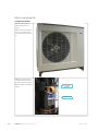
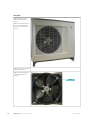
Nibe F2300 is an air/water heat pump designed for domestic use. Its operation is based on extracting energy from the outside air and converting it into heat for your home's heating system and hot water. This energy-efficient solution can help reduce your energy bills and provide a comfortable indoor climate all year round.
Nibe F2300 is an air/water heat pump designed for domestic use. Its operation is based on extracting energy from the outside air and converting it into heat for your home's heating system and hot water. This energy-efficient solution can help reduce your energy bills and provide a comfortable indoor climate all year round.


-
 1
1
-
 2
2
-
 3
3
-
 4
4
-
 5
5
-
 6
6
-
 7
7
-
 8
8
-
 9
9
-
 10
10
-
 11
11
-
 12
12
-
 13
13
-
 14
14
-
 15
15
-
 16
16
-
 17
17
-
 18
18
-
 19
19
-
 20
20
-
 21
21
-
 22
22
-
 23
23
-
 24
24
-
 25
25
-
 26
26
-
 27
27
-
 28
28
-
 29
29
-
 30
30
-
 31
31
-
 32
32
-
 33
33
-
 34
34
-
 35
35
-
 36
36
-
 37
37
-
 38
38
-
 39
39
-
 40
40
-
 41
41
-
 42
42
-
 43
43


Nibe F2300 is an air/water heat pump designed for domestic use. Its operation is based on extracting energy from the outside air and converting it into heat for your home's heating system and hot water. This energy-efficient solution can help reduce your energy bills and provide a comfortable indoor climate all year round.
Ask a question and I''ll find the answer in the document
Finding information in a document is now easier with AI
Related papers
-
Nibe F1245PC Installer Manual
-
-
Nibe F750 Installer Manual
-
Nibe SMO 20 UK Installer Manual
-
-
Nibe SMO S40 Installation guide
-
-
-
Nibe F370 Installer Manual
-
Nibe HEV 500 Installation And Maintenance Instructions Manual
Other documents
-
CTC Union CombiAir 12 Installer Manual
-
Vox WHSM35-50-65-80-100 User manual
-
Nice F470 User manual
-
Mitsubishi Heavy Industries (FDCW60VNX-W) Installation guide
-
GLP KNV Dot Quick Start And Safety Manual
-
Alpha innotec LSplit Owner's manual
-
-
ZAZU Breathing Emmy Light User manual
-
-
Mitsubishi Heavy Industries RC-HY40 Installation guide