Nibe SMO S40 Installation guide

Category
Split-system air conditioners
Type
Installation guide
Installer manual
Control module
NIBE SMO S40 UK
IHB EN 2208-1
631929
Quick guide
NAVIGATION
Browse
ScrollSelect
The dots at the bottom
edge show that there
are more pages.
If the menu has several
sub-menus, you can
see more information
by dragging up or
down with your finger.
Most options and func-
tions are activated by
lightly pressing on the
display with your finger.
Drag to the right or left
with your finger to
browse between the
pages.
Setting the indoor temperature.
13.45 3 October
Climate system 1
Offset
Heating
Smartguide
Hi!
Your system is working properly. Do you want help making
changes?
Yes please, take me to Smartguide.
October13.45 3
Here, you can set the temperature in the installation's zones.Smartguide helps you both to view information about the current
status and to make the most common settings easily. The inform-
ation that you see depends on the product you have and the ac-
cessories that are connected to the product.
Product overview
Company AB
Phone number
SMOS40
01234567890123
1.0.0
Product
overview
Product name
Serial number
Software
Service
October13.45 3
Update
Increasing hot water temperature
13.45 3 October
More hot water
Hot water
Here, you can find information about product name, the product's
serial number, the version of the software and service. When
there is new software to download, you can do it here (provided
that SMO S40 is connected to myUplink).
Here, you can start or stop a temporary increase in the hot water
temperature.
This function page is only visible in installations with a water
heater.
41 Important information
4Safety information
4Symbols
4Marking
4Serial number
5Country specific information
6Inspection of the installation
7System solutions
82 Delivery and handling
8Supplied components
9Open front hatch
9Open USB cover
9Removing the front panel
10Mounting
113 The Control Module Design
134 Installing the installation
13General
13Symbol key
14Connecting air/water heat pump
14Climate system
15Cold and hot water
15Installation alternative
185 Electrical connections
18General
19Connections
29Settings
306 Commissioning and adjusting
30Preparations
30Commissioning
30Commissioning with additional heating only
30Check the reversing valve
30Check selectable outputs
30Start-up and inspection
31Setting the cooling/heating curve
347 myUplink
34Specification
34Connection
34Range of services
358 Control - Introduction
35Display unit
36Navigation
36Menu types
38Climate systems and zones
399 Control – Menus
39Menu 1 – Indoor climate
43Menu 2 – Hot water
45Menu 3 - Info
46Menu 4 - My system
50Menu 5 - Connection
51Menu 6 - Scheduling
52Menu 7 - Installer settings
6010 Service
60Service actions
6411 Disturbances in comfort
64Info-menu
64Manage alarm
64Troubleshooting
6612 Accessories
6813 Technical data
68Dimensions
69Technical specifications
69Max load relay outputs on AA100
70Energy labelling
71Electrical circuit diagram
75Item register
79Contact information
3Table of ContentsNIBE SMO S40
Table of Contents
Safety information
This manual describes installation and service procedures
for implementation by specialists.
The manual must be left with the customer.
Symbols
Explanation of symbols that may be present in this manual.
NOTE
This symbol indicates danger to person or machine.
Caution
This symbol indicates important information about
what you should consider when installing or servi-
cing the installation.
TIP
This symbol indicates tips on how to facilitate us-
ing the product.
Marking
Explanation of symbols that may be present on the product’s
label(s).
Danger to person or machine.
!
Read the Installer Manual.
Serial number
The serial number can be found on the left-hand side of the
control module and on the "Product overview" home screen.
UN
Caution
You need the product's (14 digit) serial number for
servicing and support.
NIBE SMO S40Chapter 1 | Important information4
Important information
Country specific information
UNITED KINGDOM
This installation is subject to building regulation approval,
notify the local Authority of intention to install.
Use only manufacturer’s recommended replacement parts.
For more information see nibe.co.uk.
Benchmark places responsibilities on both manufacturers
and installers. The purpose is to ensure that customers are
provided with the correct equipment for their needs, that it
is installed, commissioned and serviced in accordance with
the manufacturers instructions by competent persons and
that it meets the requirements of the appropriate Building
Regulations. The Benchmark Checklist can be used to
demonstrate compliance with Building Regulations and
should be provided to the customer for future reference.
Installers are required to carry out the installation, commis-
sioning and servicing work in accordance with the Bench-
mark Code of practice which is available from the Heating
and Hotwater Industry Council who manage and promote
the Scheme. Visit centralheating.co.uk for information.
Warranty and insurance information
Thank you for installing a new NIBE heat pump in your home.
NIBE heat pumps are manufactured in Sweden to the very
highest standard so we are pleased to offer our customers
a comprehensive guarantee.
The product is guaranteed for 24 months for parts and la-
bour from the date of installation or 33 months from the
date of manufacture, whichever is the shorter.
The NIBE guarantee is based on the unit being installed and
commissioned by a NIBE accredited installer, serviced every
year and the Benchmark documents completed. Where this
condition is not met, any chargeable spare parts or compon-
ents issued within the applicable guarantee period still be-
nefit from a 12 month warranty from the date of issue by
the manufacturer.
We recommend the installer completes and returns as soon
as possible, your guarantee registration card or completes
the guarantee form on the NIBE website www.nibe.co.uk
5Chapter 1 | Important informationNIBE SMO S40
Inspection of the installation
Current regulations require the heating installation to be inspected before it is commissioned. The inspection must be
carried out by a suitably qualified person.
In addition, fill in the page for the installation data in the User Manual.
DateSignatureNotesDescription
Electrical connections
Communication, heat pump
Connected supply 230 V
Outside sensor
Room sensor
Temperature sensor, hot water charging
Temperature sensor, hot water top
External supply temperature sensor
External return line sensor
Charge pump
Shuttle valve
AUX1
AUX2
AUX3
AUX4
AUX5
AUX6
AUX10
AUX11
Miscellaneous
Checking additional heater
Checking the function of the reversing valve
Checking charge pump function
Completed installation check of heat pump
and associated equipment
NIBE SMO S40Chapter 1 | Important information6
System solutions
The following combinations of products are recommended for control by SMO S40.
LEK
LEK
LEK
LEK
LEK
LEK
Volume vesselAddition
Water heater
Circ. pumpAccumulator
with hot water
heater
HW control
Air/water heat
pump
Control module
UKV 40
ELK 15
VPB 300
CPD 11-25/65
VPA 300/200
VST 05
AMS 10-6 /
HBS 05-6
SMO S40
UKV 100
UKV 200
ELK 26
ELK 42
VPB 500
VPB S300
CPD 11-25/75
AMS 10-8 /
HBS 05-12
UKV 300
ELK 213
AMS 20-6 /
HBS 20-6
UKV 500
F2040 – 6
F2040 – 8
S2125 – 8
VST 11
AMS 10-12 /
HBS 05-12
F2040 – 12
S2125 – 12
VPB 500VST 20
AMS 10-16 /
HBS 05-16
F2040 – 16
COMPATIBLE AIR/WATER HEAT PUMPS
In some air/water heat pumps, manufactured before or
during 2019, the circuit board must be updated in order to
be compatible with SMO S40.
Lowest compatible software
version
Air/water heat pump
v37 (AA23 communication
board)
NIBE SPLIT HBS 05 (AMS 10,
HBS 05)
allNIBE SPLIT HBS 20 (AMS 20,
HBS 20)
v129F2030
v37 (AA23 communication
board)
F2040
allS2125
v129F2300
7Chapter 1 | Important informationNIBE SMO S40
Supplied components
Room sensorOutside sensor
LEK
Aluminium tape
LEK
Insulation tape
Temperature sensor
Cable ties
Heating pipe paste
LEK
LEK
LEK
Current sensor
NIBE SMO S40Chapter 2 | Delivery and handling8
Delivery and handling
Open front hatch
Open USB cover
Removing the front panel
Loosen the screws slightly using a screwdriver. Lift the
bottom edge of the front cover on the control module and
unhook the cover at the upper edge.
SMO S40
2x
9Chapter 2 | Delivery and handlingNIBE SMO S40
Mounting
Use all mounting points and mount the module upright, flat
against the wall.Leave at least 100 mm of free space around
the module to allow access and make cable routing easier
during installation and servicing.
Caution
The screw type must be adapted to the surface
on which installation is taking place.
Caution
Screws for removing the front cover are reached
from underneath.
SMO S40
1. If the hole for cable routing on the rear needs to be used,
remove the piece of plastic by pressing it out with a
suitable tool.
2.
3. Remove the display by moving it to the left. Detach the
cable from the lower edge
4. Mark the position of the two upper screws using a pen.
Screw in the two upper screws.
5. Hook SMO S40 onto the screws on the wall.
2x
6. Refit the display. Screw SMO S40 into place at the lower
edge with the two remaining screws.
NIBE SMO S40Chapter 2 | Delivery and handling10
UN
AA4 SF1XF3
XF8
PZ3
AA2
UB2UB1 X9 X10 X11
X2
X5
X1
X6 X8
X13 X14
X7
X12
AA100
X4X3
AA100-F2 AA2-F1AA100-F1
11Chapter 3 | The Control Module DesignNIBE SMO S40
The Control Module Design
ELECTRICAL COMPONENTS
Base cardAA2
Fine wire fuse, 4ATF1
Display unitAA4
Joint cardAA100
Fine wire fuse, 6.3ATF1
Fine wire fuse, 6.3ATF2
Terminal block, power supplyX1
Terminal block, earthX2
Terminal block (N)X3
Terminal block (L)X4
Terminal block (QN10, GP10, GP12.1-EB101,
GP12.2-EB102)
X5
Terminal block AUX outputs (AUX10)X6
Terminal block AUX outputs (AUX11)X7
Terminal block, additional heatX8
Terminal block, external connection optionsX9
Terminal block AUX inputs, external connec-
tion options (selectable AUX 1–6)
X10
Terminal block (GND)X11
Terminal block, external connectionsX12
Terminal block (GND)X13
Terminal block, external connectionsX14
On/off buttonSF1
USB socketXF3
Network connection for myUplinkXF8
OTHER COMPONENTS
Serial number platePZ3
Cable grommet, incoming supply electricity, power for
accessories
UB1
Cable grommet, communicationUB2
Designations according to standard EN 81346-2.
NIBE SMO S40Chapter 3 | The Control Module Design12
General
Pipe installation must be carried out in accordance with
applicable regulations. See manual for compatible NIBE
air/water heat pump for installation of the heat pump.
The pipe dimension should not be less than the recommen-
ded pipe diameter according to the table. However, each
system must be dimensioned individually to manage the
recommended system flows.
MINIMUM SYSTEM FLOWS
The installation must be dimensioned at least to manage
the minimum defrosting flow at 100% pump operation, see
table.
Minimum re-
commended
pipe dimen-
sion (mm)
Minimum re-
commended
pipe dimen-
sion (DN)
Minimumflow
during de-
frosting
(100% pump
speed (l/s)
Air/water
heat pump
22200.19
AMS 10-6/
HBS 05-6
AMS 10-8/
HBS 05-12
22200.29AMS 10-12/
HBS 05-12
28250.39AMS 10-16/
HBS 05-16
Minimum re-
commended
pipe dimen-
sion (mm)
Minimum re-
commended
pipe dimen-
sion (DN)
Minimumflow
during de-
frosting
(100% pump
speed (l/s)
Air/water
heat pump
22200.19
AMS 20-6/
HBS 20-6
Minimum re-
commended
pipe dimen-
sion (mm)
Minimum re-
commended
pipe dimen-
sion (DN)
Minimumflow
during de-
frosting
(100% pump
speed (l/s)
Air/water
heat pump
22200.19
F2040-6
F2040-8
22200.29F2040-12
28250.39F2040-16
Minimum re-
commended
pipe dimen-
sion (mm)
Minimum re-
commended
pipe dimen-
sion (DN)
Minimumflow
during de-
frosting
(100% pump
speed (l/s)
Air/water
heat pump
28250.32
S2125-8
(1x230V)
S2125-12
(1x230V)
Minimum re-
commended
pipe dimen-
sion (mm)
Minimum re-
commended
pipe dimen-
sion (DN)
Minimumflow
during de-
frosting
(100% pump
speed (l/s)
Air/water
heat pump
35320.47F2300-20
NOTE
An undersized system can result in damage to the
product and lead to malfunctions.
Symbol key
MeaningSymbol
Unit box
Shut-off valve
Tapping valve
Non-return valve
Mixing valve
Circulation pump
Expansion vessel
Filterball
Pressure gauge
P
Particle filter
Safety valve
Temperature sensor
Trim valve
Reversing valve/shunt
Heat exchanger
Overflow valve
Under floor heating systems
Control module
Cooling system
Air/water heat pump
Pool
Radiator system
Domestic hot water
Addition
Water heater
13Chapter 4 | Installing the installationNIBE SMO S40
Installing the installation
Connecting air/water heat pump
You can find a list of compatible air/water heat pumps in
section "System solutions".
Caution
Also, consult the Installer Manual for your air/water
heat pump.
Install as follows:
expansion vessel
pressure gauge
safety valve / safety valves
Some heat pump models have a factory-fitted safety valve
for the heating medium.
drain valve
For draining the heat pump during prolonged power fail-
ures. Only for heat pumps that do not have a gas separat-
or.
non-return valve
Installations with only one heat pump: a non-return valve
is only required in those cases where the placement of
the products in relation to each other can cause self-cir-
culation.
Cascade installations: each heat pump must be fitted with
a non-return valve.
If the heat pump is already fitted with a non-return valve,
there is no need to install another.
charge pump
shut-off valve
To facilitate any future servicing.
filterball or particle filter
Installed before connection "heating medium return" (XL2)
(the lower connection) on the vacuum pump.
In installations with a particle filter, the filter is combined
with an additional shut-off valve.
reversing valve.
If the system is to work with both a climate system and a
water heater.
trim valve
When connecting to control module and hot water heater.
P
XL1
XL2
Climate system
A climate system is a system that regulates the indoor
temperature with the help of the control system in SMO S40
and, for example, radiators, underfloor heating, underfloor
cooling, fan coils, etc.
CONNECTING THE CLIMATE SYSTEM
Install as follows:
supply temperature sensor (BT25)
The sensor indicates when the heat pump will start to
produce heating/cooling for the climate system.
When connecting to systems with thermostats on all radi-
ators/underfloor heating coils, some of the thermostats
must be removed to ensure there is sufficient flow and
heat generation.
NIBE SMO S40Chapter 4 | Installing the installation14
Cold and hot water
Hot water production is activated in the start guide or in
menu 7.1.1 - "Hot water".
Stop temperature for hot water must be at least 60°C.
CONNECTING THE HOT WATER HEATER
Install as follows:
controlling hot water sensor (BT6)
The sensor is placed in the middle of the water heater.
displayed hot water sensor (BT7)1
The sensor is optional and is placed in the top of the water
heater.
shut-off valve
non-return valve
expansion relief valve
The expansion relief valve must have a maximum 0.6 MPa
(6.0 bar) opening pressure and be installed on the incom-
ing domestic water line as shown.
mixing valve
A mixing valve must be installed when the factory setting
for hot water is changed. National regulations must be
observed.
pressure relief valve
expansion vessel
The expansion vessel (CM4) accommodates expansion
that results from heating the water inside the unit. The
expansion vessel must be connected between the expan-
sion relief valve (FL1) and the water heater. The location
of the expansion vessel should allow access to recharge
the pressure when neccessary.
tundish
1The sensor is factory fitted on some water heater/accumulator
tank models from NIBE.
XL1
XL2
Installation alternative
SMO S40 can be installed in several different ways, some of
which are shown here.
More information about the alternatives is available at
nibe.co.uk and in the relevant assembly instructions for the
accessories used. See section "Accessories" for a list of the
accessories that can be used with SMO S40.
HOT WATER CIRCULATION
A circulation pump can be controlled by SMO S40 to circulate
the hot water. The circulating water must have a temperat-
ure that prevents bacterial growth and scalding, and national
standards must be satisfied.
The HWC return is connected to a freestanding water heater.
The circulation pump is activated via the AUX output in menu
7.4 -"Selectable in/outputs".
-QZ1-AA25
-QZ1-BT70-QZ1-FQ3
-QZ1-GP11-QZ1-RM1
-QZ1
-QZ1-RN1
EXTERNAL HEATING MEDIUM PUMP
In installations where there is a large pressure drop in the
system, an external heating medium pump (GP10) can be
used as a supplement.
The installation can also be supplied with an external heating
medium pump, if you want a constant flow in the climate
system.
The heating medium pump is supplemented with an external
return line sensor (BT71) and a non-return valve (RM1).
If the installation does not have an external supply temper-
ature sensor (BT25), install this as well.
15Chapter 4 | Installing the installationNIBE SMO S40
BUFFER VESSEL UKV
UKV is an accumulator tank that is suitable for connection
to a heat pump or another external heat source, and can
have several different applications. It can also be used during
external control of the heating system.
The image shows UKV flow equalisation.
ADDITION
On cold days of the year, when the availability of energy
from the air is lower, the additional heating can compensate
and help to produce heat. The additional heating is also good
to have as assistance, if the heat pump ends up outside its
working range or if it has been blocked for any reason.
Step-controlled/shunt-controlled additional
heat
SMO S40 can, via a control signal, control step-controlled
or shunt-controlled additional heat, which can also be prior-
itised. The additional heat is used for heat production.
Step-controlled additional heat before QN10
The additional heat is connected before the reversing valve
(QN10) and is controlled via a control signal from SMO S40.
The additional heat can be used for producing both hot water
and heating.
The installation is supplemented with a supply temperature
sensor after additional heat (BT63).
FIXED CONDENSING
If the heat pump is to work towards an accumulator tank
with fixed condensing, you must connect an external supply
temperature sensor (BT25). The sensor is placed in the tank.
The following menu settings are made:
Menu setting (local variations
may be required)
Menu
Desired temperature in the tank.1.30.4 - min. flow line temp.
heating
Desired temperature in the tank.1.30.6 - max flow line temperat-
ure
intermittent7.1.2.1 - op. mod heat med pump
manual4.1 - op. mode
COOLING
Cooling in 2-pipe system
Cooling and heating are distributed via the same climate
system.
When there is a risk of condensation, components and cli-
mate systems must be insulated against condensation in
accordance with current standards and provisions.
Cooling in 4-pipe system
With the accessory NIBE AXC 30, separate cooling and
heating systems can be connected via a reversing valve.
To connect the supply temperature sensor for cooling (BT64)
and the reversing valve for cooling (QN12), see section
"Connections".
-EP45-GP10
-EP45
-EQ1-BT64
NIBE SMO S40Chapter 4 | Installing the installation16
EXTRA CLIMATE SYSTEM
In buildings with several climate systems that require differ-
ent supply temperatures, the accessory ECS 40/ECS 41 can
be connected.
A shunt valve then lowers the temperature to the underfloor
heating system, for example.
-EP21-GP10-EP21-BT2
-EP21-AA25
-EP21-BT3
-EP21-QN25
-EP21
POOL
With the POOL 40 accessory, you can heat the pool with
your system.
During pool heating, the heating medium circulates between
the heat pump and the pool exchanger using the heat
pump’s charge pump.
-CL11-HQ4-CL11-BT51-CL11-GP9
-CL11-EP5
-CL11-AA25
-CL11
17Chapter 4 | Installing the installationNIBE SMO S40
General
Electrical installation and wiring must be carried out in
accordance with national provisions.
Disconnect SMO S40 before insulation testing the house
wiring.
If the property is equipped with an RCD, the installation
should be equipped with a separate one.
SMO S40 must be installed via an isolator switch. The cable
area has to be dimensioned based on the fuse rating used.
Use a screened cable for communication with the heat
pump.
To prevent interference, sensor cables to external connec-
tions must not be laid close to high voltage cables.
The minimum area of communication and sensor cables
to external connections must be 0.5 mm² up to 50 m, for
example EKKX, LiYY or equivalent.
When cable routing in SMO S40, the cable grommets (UB1
and UB2) must be used.
Max load relay outputs on the joint board AA100, see sec-
tion "Technical specifications".
For an electrical wiring diagram for SMO S40, see the
"Technical specifications" section.
UB1 UB2
NOTE
Do not start the system before filling up with wa-
ter. Components in the system could be damaged.
NOTE
Electrical installation and any servicing must be
carried out under the supervision of a qualified
electrician. Disconnect the current using the cir-
cuit breaker before carrying out any servicing.
ACCESSIBILITY, ELECTRICAL CONNECTION
See section "Removing the front panel".
CABLE LOCK
Use a suitable tool to release/lock cables in the heat pump
terminal blocks.
Terminal block
1.
2.
NIBE SMO S40Chapter 5 | Electrical connections18
Electrical connections
Connections
TERMINAL BLOCKS
The following terminal blocks are used on the joint board
(AA100).
X10
X12
X11
X14
X13X9
X3
X7
X6
X5
AA100
X2
X1 X4 X8
POWER CONNECTION
Supply voltage
The incoming cable must be connected to terminal block
AA100-X1. Tightening torque: 0.5 – 0.6 Nm.
L N
X1
Tariff control
If the voltage to the compressor in the air/water pump is
lost for a certain period, this must be blocked simultaneously
via the selectable inputs, see section "Selectable in/outputs
– Possible selections for AUX inputs". Compressor blocking
must be performed either on the control module or on the
air/water heat pump, not on both at the same time.
EXTERNAL CONNECTIONS
Charge pump for heat pump 1 and 2
Connect circulation pump (AA35-GP12.1-EB101) to the ter-
minal block AA100-X2 (PE), AA100-X3 (N) and AA100-X5:3
(230 V).
See section "Max load relay outputs on AA100".
Control signal for AA35-GP12.1-EB101 is connected to ter-
minal block AA100-X12:1 (Pulse/0–10V) (PWM1) and GND on
any block X13.
If two heat pumps are connected to SMO S40 the circulation
pump (AA35-GP12.2-EB102) must be connected to the ter-
minal block AA100-X2 (PE), AA100-X3 (N) and AA100-X5:4
(230 V). Control signal for (AA35-GP12.2-EB102) is connec-
ted to terminal block AA100-X12:3 (Pulse/0–10V) (PWM0)
and GND on any block X13.
TIP
Two charge pumps can be connected to and con-
trolled by SMO S40. Several charge pumps can be
connected, if accessory boards (AXC) are used,
two pumps per board.
1 2 3 4
Styrmodul
N L
AA100-X3
AA100-X5
PE
AA100-X2
NNN
PE PE PE
AA100:X12
PWM1
2
3
4
1
6
5
AA100:X13
GND
GND
GND
Externt
AA35-GP12.1-EB101
SMOS40
External
Styrmodul
N L
AA100-X3
AA100-X5
PE
AA100-X2
NNN
PE PE PE 1 3 42
AA100:X12
PWM0
2
3
4
1
6
5
AA100:X13
GND
GND
GND
Externt
AA35-GP12.2-EB102
SMOS40
External
19Chapter 5 | Electrical connectionsNIBE SMO S40
Sensors
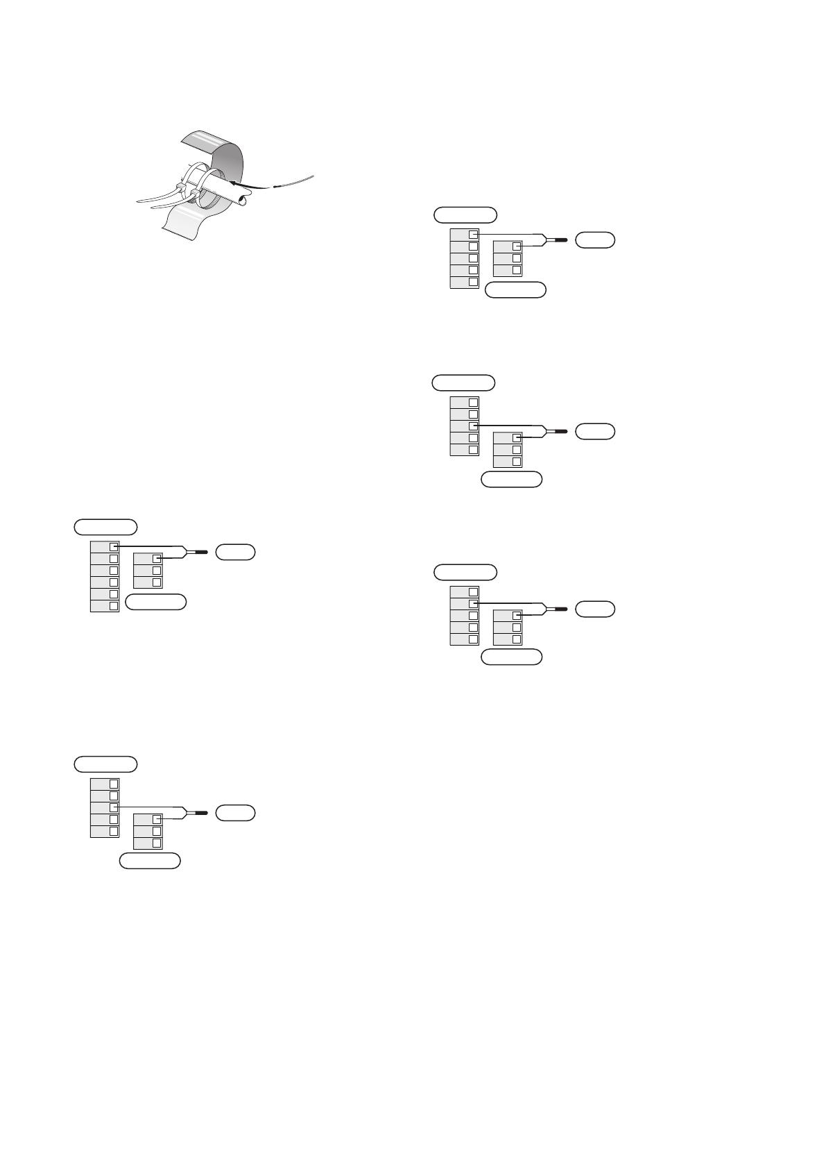
Temperature sensor installation on pipe
LEK
LEK
The temperature sensors are fitted using heat conducting
paste, cable ties (the first cable tie is secured to the pipe in
the middle of the sensor and the other cable tie is mounted
approx. 5 cm after the sensor) and aluminium tape. Then
insulate them using the enclosed insulation tape.
Outside sensor
The outdoor temperature sensor (BT1) is placed in the shade
on a wall facing north or north-west, so it is unaffected, for
example, by the morning sun.
Connect the outdoor temperature sensor to terminal block
AA100-X10:1 and AA100-X11:GND.
If a conduit is used it must be sealed to prevent condensa-
tion in the sensor capsule.
AA100-X11
2
3
4
5
6
1
BT7
BT25
BT71
BT1
BT50
BT6
AA100-X10
BT1
Temperature sensor, hot water charging
The temperature sensor, hot water charging (BT6) is placed
in the submerged tube on the water heater.
Connect the sensor to terminal block AA100-X10:3 and
AA100-X11:GND.
Settings for hot water are made in menu 2 "Hot water".
BT7
BT25
BT1
BT50
BT6
BT6
AA100-X11
AA100-X10
2
3
4
5
1
Temperature sensor, hot water top
A temperature sensor for hot water top (BT7) can be connec-
ted to SMO S40 to show the water temperature at the top
of the tank (if it is possible to install a sensor at the top of
the tank).
Connect the sensor to terminal block AA100-X10:4 and
AA100-X11:GND.
AUX1
AUX2
BT7
BT25
BT71
BT7
AA100-X11
AA100-X10
5
6
7
8
4
External return line sensor
Connect an external return line sensor (BT71) to terminal
block AA100-X10:6 and AA100-X11:GND.
AUX1
AUX2
BT7
BT25
BT71
BT71
AA100-X11
AA100-X10
5
6
7
8
4
External supply temperature sensor
Connect an external supply temperature sensor (BT25) to
terminal block AA100-X10:5 and AA100-X11:GND.
AUX1
AUX2
BT7
BT25
BT71
BT25
AA100-X11
AA100-X10
5
6
7
8
4
Room sensor
SMO S40 is supplied with an enclosed room sensor (BT50)
that makes it possible to display and control the room tem-
perature.
Fit the room sensor in a neutral position where a set temper-
ature is required. A suitable location might be, for example,
on a free inner wall in a hall approx. 1.5 m above the floor. It
is important that the room sensor is not obstructed from
measuring the correct room temperature, for example by
being located in a recess, between shelves, behind a curtain,
above or close to a heat source, in a draught from an external
door or in direct sunlight. Closed radiator thermostats can
also cause problems.
SMO S40 operates without room sensor, but if you want to
read the home’s indoor temperature from the display on
SMO S40, the room sensor must be fitted. Connect the room
sensor to terminal block AA100-X10:2 and AA100-X11:GND.
NIBE SMO S40Chapter 5 | Electrical connections20
  • Page 1 1
  • Page 2 2
  • Page 3 3
  • Page 4 4
  • Page 5 5
  • Page 6 6
  • Page 7 7
  • Page 8 8
  • Page 9 9
  • Page 10 10
  • Page 11 11
  • Page 12 12
  • Page 13 13
  • Page 14 14
  • Page 15 15
  • Page 16 16
  • Page 17 17
  • Page 18 18
  • Page 19 19
  • Page 20 20
  • Page 21 21
  • Page 22 22
  • Page 23 23
  • Page 24 24
  • Page 25 25
  • Page 26 26
  • Page 27 27
  • Page 28 28
  • Page 29 29
  • Page 30 30
  • Page 31 31
  • Page 32 32
  • Page 33 33
  • Page 34 34
  • Page 35 35
  • Page 36 36
  • Page 37 37
  • Page 38 38
  • Page 39 39
  • Page 40 40
  • Page 41 41
  • Page 42 42
  • Page 43 43
  • Page 44 44
  • Page 45 45
  • Page 46 46
  • Page 47 47
  • Page 48 48
  • Page 49 49
  • Page 50 50
  • Page 51 51
  • Page 52 52
  • Page 53 53
  • Page 54 54
  • Page 55 55
  • Page 56 56
  • Page 57 57
  • Page 58 58
  • Page 59 59
  • Page 60 60
  • Page 61 61
  • Page 62 62
  • Page 63 63
  • Page 64 64
  • Page 65 65
  • Page 66 66
  • Page 67 67
  • Page 68 68
  • Page 69 69
  • Page 70 70
  • Page 71 71
  • Page 72 72
  • Page 73 73
  • Page 74 74
  • Page 75 75
  • Page 76 76
  • Page 77 77
  • Page 78 78
  • Page 79 79
  • Page 80 80

Nibe SMO S40 Installation guide

Category
Split-system air conditioners
Type
Installation guide

Ask a question and I''ll find the answer in the document

Finding information in a document is now easier with AI