Page is loading ...

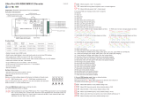
DMX/RDM High Volt LED Strip Controller
Input
Voltage Max Load
Output
Voltage
AC 100-240V 660W@110V
1320W@220V
Max. 4x1.5A
DC 100-240V
Output
Current
09.218HP.04263
Function introduction
Product Data
Size(LxWxH)
180.5x73.6x38mm
Important: Read All Instructions Prior to Installation
• RDM enabled DMX high voltage LED strip controller
• Output for high voltage DC100~240V LED Strip
• Standard DMX512 compliant control interface
• RDM function enabled to realize intercommunication between DMX master and decoder.
• For example, DMX decoder’s address can be assigned by DMX master console
• With digital display to show data directly, easily to set and show DMX address.
• Total 4 channels LED output, common anode
• DMX address manually settable
• DMX channel quantity from 1CH~4CH settable
• Output PWM frequency from 500HZ ~ 35K HZ settable, but do not set it higher than 3KHz.
• Output dimming curve gamma value from 0.1 ~ 9.9 settable
• Waterproof grade:IP67
AC100-240V
power input
AC DMX512&RDM Controller
IP67
PRI:
Uin=1 00-24 0VAC
Iin=6 A Max
ta:-2 0℃-+50℃
SEC:
Uout= 4x(100-2 40)VD C
Iout= 4x1.5A
Pout= 4x(150-3 60)W
DMX
INPUT
DMX
OUTPUT
AC
INPUT
DC
OUTPUT
Ambient
Temp.
-20℃-+50℃
• DO NOT install with power applied to device.
• This device is IP67 rating and protected against damp environment.
Safety & Warnings
To set desired DMX512 address ,
button A is to set “hundreds” position,
button B is to set “tens” position,
button C is to set “unit” position.
through buttons
Choose DMX Channel
Press and hold down both buttons B+C simultaneously for over 3 seconds, CH digital display flashes, then
keep short pressing button A to choose 1/2/3/4, which means total 1/2/3/4 channels. Press and hold down
button A for >3 seconds to confirm the setting. Factory default is 4 DMX channels.
(Factory default DMX channel is 4CH)
Choose PWM frequency
Press and hold down both buttons A+B simultaneously for over 3 seconds, digital display will show PF1, PF
means output PWM frequency, the digit 1 will flash, which means frequency, then keep short pressing button C
to select a frequency from 0-9 and A-J, which stand for following frequencies:
0=500Hz, 1=1KHz, 2=2KHz, ..., 9=9KHz, A=10KHz, B=12KHz, C=14KHz, D=16KHz, E=18KHz, F=20KHz,
H=25KHz, J=35KHz.
Then press and hold down button C for >3 seconds to confirm the setting.
Note: DO NOT set the PWM frequency higher than 3KHz to avoid over heat and damage to the device.
(Factory default PWM frequency is PF1 1KHz)
Operation
Set DMX address (Factory default DMX address is 001)
Press and hold down any of the 3 buttons for over 3 seconds, digital display flashes to enter into address
setting, then keep short pressing button A to set “hundreds” position, button B to set “tens” position, button C to
set “units” position, then press and hold down any button for >3 seconds to confirm the setting.
Choose Dimming Curve Gamma Value
Press and hold down all buttons A+B+C simultaneously for over 3 seconds, digital display flashes g1.0, 1.0
means the dimming curve gamma value, the value is selectable from 0.1-9.9, then keep short pressing button B
and button C to select corresponding digits, then press and hold down both buttons B+C for >3 seconds to
confirm the setting.
(Factory default dimming curve value is g1.0)
<1
1.0
1.5
2.5
3.5 6.5
0.90.9
0.8
gamma
value
output
brightness
level
>1
DMX value level
For example the DMX address is already set as 001.
1CH=1 DMX address for all the output channels, which all will be address 001.
2CH=2 DMX addresses , output 1&3 will be address 001, output 2&4 will be address 002
3CH=3 DMX addresses, output 1, 2 will be address 001, 002 respectively, output 3&4 will be address 003
4CH=4 DMX addresses, output 1, 2, 3, 4 will be address 001, 002, 003, 004 respectively
DMX signal indicator : When DMX signal input is detected, the indicator on the display following after the digit
of “hundreds” position of DMX address turns on red .
A B C
D+
D-
GND
DMX512 signal input
Common Anode Output(+)
CH 3:B output(-)
CH 4:W output(-)
CH 1:R output(-)
CH 2:G output(-)
D+
D-
GND
DMX512 signal input
Grey Wh ite:D +
Blue: D-
Black :GND
DMX INP UT/
OUTPU T
DC 100-240V
LED OUTPUT
Brown : V+
Black : R-
Yell ow+Gr een : G-
Blue :B -
Grey Wh ite: W-

Restore to Factory Default Setting
Press and hold down both buttons A+C for over 3 seconds until turns on
again, all settings will be restored to factory default.
Default settings are as follows:
DMX Address: 001
DMX Address Quantity: 4CH
PWM Frequency: PF1
Gamma: g1.0
the digital display turns off and then
The supported RDM PIDs are as follows:
DISC_UNIQUE_BRANCH
DISC_MUTE
DISC_UN_MUTE
DEVICE_INFO
DMX_START_ADDRESS
IDENTIFY_DEVICE
SOFTWARE_VERSION_LABEL
DMX_PERSONALITY
DMX_PERSONALITY_DESCRIPTION
SLOT_INFO
SLOT_DESCRIPTION
MANUFACTURER_LABEL
SUPPORTED_PARAMETERS
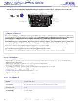
Wiring diagram
DMX
Master
D+
D-
GND
AC Power
100-240VAC
High Vol t RGBW LE D Strip
AC Power
100-240VAC
High Vol t Tuna ble Whi te LED St rip
High Vol t Singl e Color L ED Stri p
170.0
180.5
73.6
38.0
Product Dimension
V+ V+
WW WW
CW CW
WW WW
CW CW
V+ V+
R- R-
G- G-
B- B-
W- W-
High Vol t Singl e Color L ED Stri p
AC Power
100-240VAC
V+ V+
1- V-
2- V-
3- V-
4- V-
AC DMX512&R DM Co ntr oll er
IP67
PRI:
Uin= 100-2 40VAC
Iin= 6A Max
ta:- 20℃-+50℃
SEC:
Uout =4x(1 00-24 0)VDC
Iout =4x1. 5A
Pout =4x(1 50-36 0)W
DMX
INP UT
DMX
OUT PUT
AC
INP UT
DC
OUT PUT
Grey W hite: D+
Blue :D-
Blac k:GND
DMX IN PUT/
OUTP UT
DC 10 0-240 V
LED O UTPUT
Brow n :V+
Blac k :R-
Yello w+Gre en :G-
Blue : B-
Grey W hite: W -
/