Page is loading ...


1. General safety instructions
Before first use read the manual carefully and follow the
instructions contained therein. The manufacturer is not
liable for damage caused by equipment used
inappropriately or by incorrect handling.
1.1. Electrical safety
1. The electrical supply system must be fitted with a
residual-current circuit breaker with rated tripping
current not higher than 30mA. Performance of the
circuit breaker should be checked periodically.
2. Periodically check the condition of the power cord.
Replace the power cord if damaged. Replacing the
power cord can only be performed by the manufacturer
or by qualified personnel.
Do not use the device if the power cord is damaged!
3. Make sure that the main switch is in „0” position before
plugging the unit in.
4. Make sure that the nominal voltage of the device and
power source are compatible.
5. Carefully insert the plug into the mains socket. Make
sure your hands and the floor surface in the room are
dry!
6. Disengage the Emergency Switch before starting the
device.
7. The cover must be closed during operation! Do not
open the cover while the basket is rotating!.
8. Protect the motor and the control unit from moisture
(also during storage).
9. Do not pull the power cord.
Keep the power cord away from heat sources and
sharp edges to ensure its good condition.
1.2. Operation safety
1. The device is not intended for use by persons (including
children) with limited physical, sensory or mental
abilities, or by inexperienced users, unless under
supervision or with instructions given by an accountable
party.
This device is not a toy, and shouldn’t be used as one.
Children should not to play with it.
2. In the event of damage to the device, to avoid any
health and safety risks, repairs should be carried out
only by qualified personnel.
3. Never carry out any maintenance or repairs during
operation or if the device is plugged in!
4. All covers must be firmly attached to the device during
operation
5. In case of any danger use the safety switch
immediately. The device can be restarted after the
hazard has been eliminated.
6. For indoor use only. The device is not suitable for
outdoor use.
7. Do not use or store the device at the ambient
temperature below freezing. If the device has been
moved from a cold room to a room with a higher
temperature, before switching on wait until it reaches
room temperature.
8. All components of the line must be levelled prior the
operation.
Never carry out any repairs during operation
Do not remove covers during operation
9. Instructions for use
2.1. Extraction line’s components
The extraction line consists of:
mechanical uncapping machine with closed circuit
heating system, output 4-6 frames/min.
Frame feeder for 1500 mm with loading trolley
horizontal honey extractor with 2" ball valve
productivity 200-400 frames/hour.
Frame receiver rails for extracted frames 1500mm.
Wax extruder 100kg.
tank with a perforated insert sieves and a float
switch
honey pump 900l/hour.
Technical specifications:
voltage 230V
Total power consumption 4kW
Dimensions: H: 7m, W:.2,5m, H:2,5m.
Recommended free space around the device ~1m
Net weight: 420kg.
2.2. Installation
1. Place the extractor in its dedicated place Fig.1
2. Level the extractor using appropriate tools
1

3. Recommended height of the foot extensions
~ 20mm. Fig.1a
4. Secure the extractor to the ground using
dowels (Ø14 or Ø16, min. 150 mm long, dowels not
included)
Fig.1. Extractor Fig.1a. Recommended foot length
Fig.2. Frame feeder and the uncapping machine
5. Attach the frame feeder with a loading trolley and a
factory-assembled uncapping machine to the honey
extractor (on the left of the extractor) Fig.3
6. Using M8x20 allen screws secure the uncapping
machine assembly to the extractor; it should be properly
positioned in relation to the extractor and levelled Fig.3
Fig.3. Attaching points
7. Place the receiver to the right side of the extractor
Fig.4
8. Using M8x20 allen screws secure the receiver
assembly to the extractor; it should be properly positioned
in relation to the extractor and levelled
Fig.4. Frame receiver
2


3. Preparation for use
Before first use:
check that all its elements have been correctly
connected according to the instructions
check all the electrical connections
thoroughly clean all line components as indicated
in the MAINTENANCE AND CLEANING section
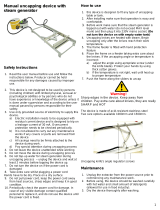
Phase I. Preparing the uncapping machine
Phase II. Setting the extractor’s controller
Phase III. Setting the pump’s controller
Phase IV. Starting uncapping and extracting
Phase V. Starting the wax extruder
3.1. Phase I. Preparing the
uncapping machine
Before starting the uncapping machine:
Fill the steam generator (2) with distilled water
through the fill port/vent plug (3)
Set the water circulation pump switch (7) to "1", plug
in the heating unit to the power supply socket and
switch it on using the switch (5)
Wait until the temperature in the circuit and the
uncapping knives (14) have reached the
temperature preset on the thermostat (1).
The water in the steam generator starts to steam.
Turn the switch (8) on the control box (9), RIGHT or
LEFT to activate the frame feeder chains (11) and
the uncapping machine chains (14).
Place the previously prepared frames on the
working feeding chain (11), paying special attention
to their correct positioning (parallel to each other
and perpendicular to the chains). Miss-arrangement
of the frames may cause damage to the frames or
the uncapping system.
Use the RIGHT/LEFT switch (8) to control the
process of feeding the frames to the uncapping
machine or to move the frames back if they get
stuck on the feeder or chains of the uncapping
machine.
The uncapping knives (14) can be adjusted in depth
with two dedicated levers, locking (15) and adjusting
the distance between the knives (16)
The adjustment should be made after inspecting the
test uncapped frame (whether the knives cut too
deeply or too shallow and some of the cells are still
sealed)
The uncapped frames are pushed one after another
on the uncapping machine’s receiving rails
Using a trolley, push the uncapped frames into the
extractor.
The cappings from the uncapping process fall into
the extruder.
Do not make any adjustments while the uncapping
machine is running.
Uncapping machine
1-heating element with thermostat
2-water heater tank
3-filling port & vent
4-power cord
5-main switch
6. heater’s controller casing
7- circulating pump
8-left/right switch
9-uncapping machine’s controller casing
10-safety switch
11-chain feeder
12. uncapping machine’s motor
13. power cord
14-uncapping knives
15-locking lever
16-adjustment lever
Fig.1
1 2 3
4 5 6 7
4


Using the loading trolley move the frames in the
direction of the honey extractor Fig. 2
Fig.1 Loading trolley
Fig.2 Operation of the loading trolley
Open the extractor, rotate the basket in the loading position
and lock it in place with the dedicated latches on both ends
of the basket Fig. 3 & 4
Fig.3 Locking position of the basket
Fig.4 Basket locked
Slide the appropriate number of frames into the basket, 20
frames per section. The basket has 2 sections. It is
important to load the extractor with the full number of
frames. A smaller quantity can cause the frames to fall out
of the basket during the extraction process and can cause
damage the basket Fig. 5
Fig.5 Incorrectly positioned frames in the basket
Unlock the basket (slide back the "paws"), the frames are
automatically blocked Fig.4. Check the position of the locks
in the "closed" position. Rotate the basket to the second
section and fill it with frames. When the basket is full, close
the extractor and start the controller.
After the extraction cycle has finished, the basket stops.
Opening the cover of the honey extractor, rotate the basket
in to the loading/unloading position and lock it in place (both
sides) Fig.4.
While loading the next batch of uncapped frames into the
extractor the extracted frames are automatically pushed out
of the basket. They slide onto the receiver rails from where
they can be lifted out and put back into the hive’s body.
The extracted honey flows down to the sump equipped with
initial filtration sieves, from where with the use of a pump, it
is pumped into the transport/storage containers (settling
tank, barrel). The float switch which is fitted in the sump
controls the level of the honey and turns of the pump when
it is necessary.
The wax from the uncapped frames fall directly into the
extruder, which is activated together with the uncapping
capping machine. The honey which is pressed out of the
wax during extrusion process flows from the extruder tray
into the sump.
The sump is connected to the honey separator, the pump
and the extruder.
10

3.5. Phase V– starting the wax
extruder
The operation of the controller comes down to switching on the
extruder motor by pressing button 1 or 3 with user-defined
speed set by knob 7.
7
4 5 6
3 2 1
DESCRIPTION OF THE BUTTONS/FUNCTIONS
OF THE CONTROLLER
Symbol Funkction
1RIGHT START button. Pressing the button
starts the extruder in continuous operation
mode. The cycle is stopped by pressing the
STOP button (2)
2STOP button. Pressing the button stops the
extruder.
3LEFT START button. Pressing the button
starts the extruder in continuous operation
mode. The cycle is stopped by pressing the
STOP button (2)
4 LED indicating the extruder rotating direction
left
5 LED indicating the inactive status. Flashing
diode indicates that the safety loop is
tripped.
6 LED indicating the extruder rotating direction
right
7 Speed control knob (speed setting from 0 -
max). Setting the speed to 0 does not stop
the device from working
Controller’s operation
After switching on the power, the controller performs a start-up
sequence – conducting several basic diagnostic tests to
confirm correct operation of the device. If any errors are
detected the controller signals it by the blinking of the LED 4
and lighting up an appropriate combination of LEDs 5 and 6. If
no errors are detected, the controller goes into the stop state –
awaiting user input.
The controller is operated by starting the extruder using button
1 or 3. The STOP button stops the extruder and switches off
the performed operation. The cycle starts again after button 1
or 3 is pressed.
Detection of the safety loop activation (pressing the
emergency STOP button) causes immediate stopping of the
motor rotation.
Releasing the safety loop (turning the STOP button clockwise)
returns the device to the active state.
11


8. Technical specifications
Horizontal extractor :
- for 40 frames (two sections)
- motor 0,75 kW
- power supply 230V
- 2" ball drain valve
- dimensions length 1370 / width 1150 / height 1450 mm
Uncapping machine with chain feeder:
- capacity 4-6 frames/min.
- hot water in a closed circuit heated knives
- hot water generator – capacity 8,5 L.
- power: 2,1 kW
- power supply 230V
- dimensions of uncapping machine: length 1100 / width 1000 /
height 1900 mm
Frame feeder with manual loading trolley:
- length: 1500 mm
Frame receiver:
- single, length: 1500 mm
- Dimensions: L 1600 / W 700 / H 1500 mm
Wax extruder:
- capacity up to 100 kg/h
- adjustable rotation speed of the screw: max 9 rpm
- power 0,55 kW
- power supply 230V
Honey pump:
- capacity: 900l/h
- power: 0,37 kW
- power supply: 230V
- Dimensions: L 700 / W 400 / H 650 mm
Honey sump with perforated insert for initial cleaning:
- capacity 120 l
Dimensions of other components:
- Extruder: length 1100 / width 750 / height 850 mm
- Sieve: length 1150 / width 800 / height 300 mm
Overall dimensions of the line:
- length 5000 mm
- width 1700 mm
- height 1900 mm
Net weight of the line compenents:
- total 420 kg
- extruder 80 kg
- pump 25 kg
- sieve + float switch 15 kg
- extractor + feeder + receiver + uncapping machine 300 kg
13
/