18 of 28
888-24-302-G-01 rev. H • 03/19
16
1x
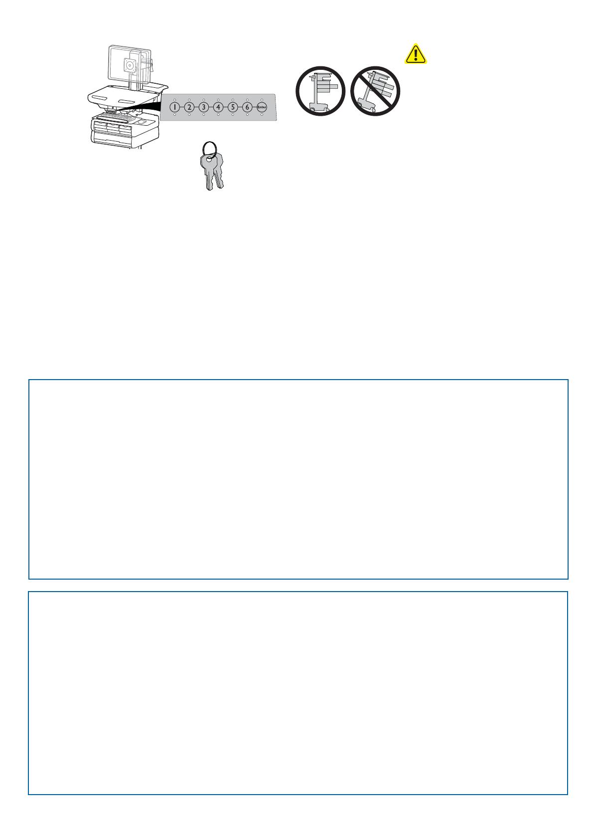
Auto-Lock Drawer
CAUTION: Open only one drawer at a time. Do
Not push cart when drawers are open. Failure
to follow these instructions may cause the cart
to be unstable.
Lost Master PIN
Contact Ergotron Customer Care for instructions.
Ensure that the main power system batteries are installed and functioning. The power does not need to be
turned on at the power system user interface.
Programming Pharmacy PIN
1. Enter Master PIN and press ENTER for Mode Menu
2. Press 2 for Pharmacy PIN Entry Mode
3. Input Pharmacy PIN and press ENTER (all LEDs blink green in PIN is accepted).
4. Pharmacy PIN entry mode will exit after 5 seconds of inactivity (LEDs blink red twice).
Programming User PINS
1. Enter Master PIN and press ENTER for Mode Menu.
2. Press 1 for User PIN Entry Mode.
3. Input new User PIN and press ENTER (All LEDs blink green if PIN is accepted). You may enter multiple USER PINs consecutively.
4. User PIN entry mode will exit after 5 seconds of inactivity (LEDs blink red twice).
NOTE: User PIN cannot be the same as a Master PIN or Pharmacy PIN. Once maximum User PIN storage is exceeded, the oldest User PIN will be over written.
Note: System will hold 1 Pharmacy PIN. Pharmacy PIN allows all drawers to unlock at the same time. Drawers should then be opened at least slightly as the system will auto-lock after 15 seconds. All LEDs will
ash green until system auto-locks. Once a drawer is opened the corresponding LED for that row will light solid until it is placed back into its original location.
If drawers are removed from cart for lling, they must be replaced in the same con guration per row. If they are not, power must be removed and reapplied so that the drawer system recon gures itself.
Set-up Master PIN for the First Time (Default Master PIN: 12345)
Contact Ergotron Customer Care for instructions if Master PIN is lost.
1. Enter default Master PIN (1-2-3-4-5) then press ENTER.
2. Press 5 for Master PIN change mode
3. Enter new Master PIN and press Enter (LEDs will blink green if PIN is accepted)
4. Master PIN entry mode will exit after 5 seconds of inactivity (LEDs blink red twice)
Master PIN Mode Menu
(NOTE: Master PIN does not open drawers.)
Enter Master PIN and then select one of the below numbers to enter that mode
1. After entering Master PIN, Select 1 to access User PIN Entry Mode
2. After entering Master PIN, Select 2 to access Pharmacy PIN Entry/Change Mode
5. After entering Master PIN, Select 5 to access Master Pin Change Mode
6, 1. After entering master PIN, select 6 then select 1 to disable alarm. Repeat process to enable alarm.
6, 2. After entering master PIN, select 6 then select 2 to enable bulk unlock mode. This will cause all drawers to open when any user PIN is entered. Repeat process to revert back to default.
6, 6, Master PIN, Enter. After entering master PIN, select 6 then select 6 again, then enter Master PIN again, then select Enter. This will reset keypad to the factory default Master PIN as 1, 2, 3, 4, 5, and will also delete
all User PINs and Pharmacy PIN.
User PINs:
Without StyleLink management:
- PINs entered on the cart and not managed by StyleLink may vary in length from 4-7 digits.
- Ergotron recommends the following for choosing PIN digit length (assumes less than 1 in 25 chance of guessing random User PIN):
Max number of User PINs >50, 5+digit length recommended
Max number of User PINs >300, 6+digit length recommended
For maximum security use PIN length of 7
- Carts store up to 1,000 PINs.
With StyleLink management:
- Maximum 100 PINs per cart.
- 5 digit PIN length required.
NOTE: Change Master Personal Identi cation Number (PIN) upon receipt of cart.
A User PIN must be created to open drawers electronically.


