Page is loading ...

Weather Forecast RF Wall Clock
with Romote Thermometer
Model: JMR818WF
User Manual
JMR818WF-E Cover R1 R OP 8/27/04, 6:00 PM1

1
GB
INTRODUCTION
Congratulations for purchase of the Weather Forecast RF Wall
Clock with Remote Thermometer (JMR818WF).
The JMR818WF is a multifunction radio frequency (RF) controlled
clock. When brought within a 1500km radius of Frankfurt,
Germany a radio signal generated from (DCF77) will emit signals
that can accurately synchronize this device to the current time
and date.
Also, the JMR818WF displays outdoor and indoor temperature
and uses barometric information to indicate weather forecasts
and atmospheric pressure trends.
Included in this package is a remote thermo-sensor. Place the
thermo-sensor in a sheltered outdoor location within a 30-meter
radius of the main unit and it will transmit outdoor temperature
readings to the JMR818WF.
Other features include a daily crescendo alarm with an eight-
minute snooze function, and extra-large display.
DESCRIPTION OF PARTS
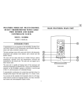
A MAIN UNIT
A1 Extra-large liquid crystal display (LCD)
• Displays the time, date and day-of-the-week
• Alarm status, and alarm-set time
• Weather forecast and pressure trends
• In/outdoor temperatures in ºC
A2 [
] Radio-reception signal
Indicates the condition of radio reception
A3 [
] Alarm-on icon
Appears when the alarm is activated
A4 [
] Alarm icon
Appears when the alarm time is displayed
A5 [
BATT
] Battery-low indicator
Activates when the battery power is low
A6 [ ] Battery-low indicator (remote sensor)
Activates when the remote-sensor battery power is low
A7 Trend indicator
Indicates the trend of pressure changes
A8 Weather-forecast icons
[
] Displays Weather
forecasts as sunny, partly cloudy, cloudy and rainy
WEATHER FORECAST RF WALL CLOCK
WITH ROMOTE THERMOMETER
JMR818WF
User Manual
A9 Bottom line of LCD showing alarm time and day-of-
the-week and outdoor temperature
User-select display option
A10 [ ((
SNOOZE
)) ] Alarm-delay button
Activates the snooze function
A11 [
CLOCK
] button
Toggles between “seconds” and day-of-the-week displays
or activates the calendar-clock setting mode
A12 [
] UP button
Increases the value of a setting
JMR818WF-E R1 R OP 8/27/04, 6:00 PM1
Black

2
GB
A13 [
ON/OFF
] button
Activates and deactivates the alarm
A14 [
THERMO
] button
Alternates temperature display between indoor, outdoor,
and combined in / outdoor viewing display
A15 [
ALARM
] button
Displays the alarm-time or sets the alarm status
A16 Sensor
For indoor temperature reading
A17 [
RESET
] Button
Resets the unit by returning all settings to their default
values
A18 Battery Compartment
Accommodates four UM4 or AAA-size batteries
A19 Alarm
Sound vents for daily alarm
A20 Table Stand
For placing the unit on a flat surface
A21 Wall-Mount Hole
For mounting the unit on a wall
B REMOTE THERMO SENSOR
B1 LCD
Displays the current temperature monitored by the remote
unit
B2 LED indicator
Flashes when the remote unit transmits a reading
B3
°C/°F slide switch
Selects between Centigrade (°C) and Fahrenheit (°F)
B4 [ ] Battery-low indicator
Activates when the battery power is low
B5 Reset button
Returns all settings to default values
B6 Battery compartment
Accommodates two UM-4 or AAA size alkaline batteries
B7 Battery door
B8 Wall-mount holder
Supports the remote unit in wall-mounting
B9 Removable table-stand
For standing the remote unit on a flat surface
BATTERY INSTALLATION AND REMOTE
THERO-SENSOR SETUP
Follow this step-by-step procedure for installing batteries and
setting up the remote-sensor unit. Successful setup should ensure
that temperature signals are properly received.
Note: The effective range may be limited by building
materials and the position of either the main unit or the
remote thermo-sensor unit. Try various set-up arrangements
for best result.
Setting up the thermo-sensor unit:
The remote unit uses two (2) UM-4 or “AAA” size batteries.
Installation:
1. Remove the outer battery compartment door.
2. Remove inner screws and open the inner clearplastic
compartment door.
3. Select the temperature display unit on the °C/°F slide switch.
4. Insert the batteries strictly according to the polarities shown.
5. Replace the battery compartment door and secure its screws.
JMR818WF-E R1 R OP 8/27/04, 6:00 PM2
Black

3
GB
Note: Though the sensor is splash proof, and is meant for
use outside, it should be placed away from direct sunlight,
rain, or snow.
Once the batteries have been inserted into the remote thermo-
sensor unit, batteries can now be inserted into the main unit.
The JMR818WF (main unit) requires four (4) UM4 or “AAA”
size batteries for operation.
How to insert batteries into the main unit:
1. Press the door tab and click-open the door.
2. Insert the batteries strictly according to the polarities shown
therein.
3. Replace the door so that it clicks into place.
Note: If not disposed of properly, batteries can be
harmful. Protect the environment by taking exhausted
batteries to authorized disposal stations.
Note: [
BATT
] Battery-low indicator
Replace the batteries when the battery-low indicator lights
up.
ABOUT RADIO RECEPTION
The JMR818WF is a radio frequency (RF) controlled clock.
When located within a 1500km radius of radio signal (DCF77) at
Frankfurt, Germany, the clock time will automatically synchronize
with DCF77 time-signal transmission. The benefit of a RF
controlled clock is that highly-accurate time is maintained and
manual adjustments to the time and date are not be required.
When the batteries are first installed, the JMR818WF will
automatically search for a radio signal.
When in search mode, the antenna icon [
] will blink. This
process takes between two (2) and (10) minutes. After initial
search, short periodic reception-signal scans will commence
several times a day.
The antenna icon indicates the quality of reception.
STRONG
WEAK
NO RECEPTION
RECEIVING
Interference
Reception can be affected by a number of factors. For best reception,
place the device away from metal objects and electrical appliances.
Note: Interference from sources such as TV sets can affect
the signal. If, after batteries have been inserted for ten
minutes, the DCF77 signal is not received, then set the
time manually (see section: How To Set The Calendar
Clock Manually).
“SECONDS” AND DAY-OF-THE-WEEK
DISPLAY
The “second” and the day-of-the-week share the same section of
the display.
day-of-the-week display
“second” display
The day-of-the-week is displayed as an abbreviation in four
languages.
JMR818WF-E R1 R OP 8/27/04, 6:00 PM3
Black

4
GB
Day-of-the-week
Language
Monday Tuesday Wed. Thursday Friday Saturday Sunday
English
German
French
Italian
To change the “seconds” display to the day-of-the-week
display:
1. When the “seconds” are displayed, press CLOCK once.
To change the day-of-the-week display to the “seconds”
display:
1. When the day-of-the-week is displayed, press CLOCK once.
CALENDAR AND ALARM TIME DISPLAY
The calendar and the alarm-time share the same section of the display.
The calendar is displayed in a day-month format.
calendar mode
alarm mode
To change the calendar display to the alarm-time display:
2. When the calendar is displayed, press ALARM once.
To change the alarm-time display to the calendar display:
2. When the alarm time is displayed, press ALARM once.
HOW TO SET THE CALENDAR CLOCK
MANUALLY
When the unit is outside of the 1500km radius of the radio signal
DCF77 generated from Frankfurt, Germany, the unit may require
manual setting.
Note: The RF controlled mechanism overrides manual
settings. If manual settings are made, the clock will
periodically adjust the time to what is indicated by the
radio signal.
To manually set the clock:
1. Press CLOCK and hold for two seconds. The hour digits will
start to flash.
2. Enter the correct month using the [ ] button. Hold to
rapidly increase the value.
3. Press CLOCK to confirm and proceed to set the minutes.
Again, use the [ ] button to select the correct minutes.
4. Press CLOCK to confirm and proceed to enter the current
date and the current month.
5. Next, select a language for the days of the week. To choose a
language press [
] button.
6. Finally, press CLOCK to proceed to the day-of-the-week.
Proceed in the same manner.
7. When finished, press CLOCK. The time and date are now
set.
TO SET AND ACTIVATE THE ALARM
The calendar display and the alarm display share the same section
of the display.
To set the alarm-time:
1. Press and hold ALARM for two seconds, the alarm time will
flash.
2. Press [
] to enter a value for the hour digits. To confirm,
press ALARM and proceed to the minute digits.
3. Again, press [ ] to enter a value for the minute digits.
Press ALARM to confirm.
To activate the alarm:
Press [
ON/OFF
] . When the [
] icon is visible on the
display, the alarm is set and will activate at the set time.
To deactivate the alarm, press [
ON/OFF
] once.
ALARM AND SNOOZE FUNCTION
When the alarm function is active, the unit will alarm at the set
time.
Resulting from the crescendo function, the alarm initially starts
gently and increases in intensity in three stages. Without
interruption, the alarm will activate for (2) two-minutes.
To stop the alarm, press any key. However, if the [ ((
SNOOZE
)) ]
is pressed, the snooze function will be triggered. The alarm will
stop for eight minutes before activates again.
JMR818WF-E R1 R OP 8/27/04, 6:00 PM4
Black

5
GB
TEMPERATURE DISPLAY
The JMR818WF displays temperature in Centigrade (°C). A
user-select option lets the user choose between indoor, outdoor
or alternating displays.
indoor temperature display
outdoor temperature display
To display either the indoor, outdoor, or alternating
temperature displays:
• Press THERMO to alternate between the temperature displays.
Note: The alternating display will alternate between the
indoor and outdoor display about every 9-seconds. The IN
and OUT symbols will flash to indicate that the unit is in
the alternating temperature display.
The outdoor temperature display has a kinetic-way display.
The kinetic-wave display shows the signal-receiving status by
the main unit. The are three possible forms.
The unit is in searching mode.
Temperature readings are
securely registered.
No signals
SENSOR TRANSMITION STATUS
If blanks "----" appear on the outdoor temperature display of the
main, then the unit is not receiving a signal from the remote
thermo sensor. The user may be able to receive a signal by
forcing a signal search.
To force a remote sensor signal:
Press and hold [THERMO] for 2-seconds. The unit will search
for a remote thermo-sensor signal.
Search mode will last for 67-seconds. If the unit still cannot
receive a signal, check the batteries to ensure they are properly
installed and have ample power. Try repositioning the units as
they may be having temperature transmission block as a result of
interference.
Note:
Reasons for not receiving a signal from the remote thermo
sensor may include:
1. The batteries of the remote sensor, the main unit, or
both may be low. Battery-low icons should indicate that
battery power is low and the batteries require changing.
• When the temperature falls below freezing point, the
batteries will freeze. Frozen batteries will have a
lower voltage and result in a lower transmission
radius.
2. The transmission range is too far.
• Shorten the distance.
3. The transmission path is cluttered with obstacles and
interference.
• Shorten the distance or reposition the remote sensor
or the main unit.
HOW TO READ THE PRESSURE TREND
The JMR818WF gives a pressure trend for the last hour. As
illustrated below, a rising trend (arrow) indicates improving
weather. Deteriorating weather conditions are indicated with a
falling trend (arrow).
WEATHER FORECAST FUNCTION
The JMR818WF detects barometric pressure changes and displays
the illustrated weather symbols that indicate weather forecasts
for 12 to 24 hours. The radius of the forecast is approximately
30 - 50 km.
PRESSURE PRESSURE PRESSURE
Arrow
Indicator
Pressure
Trend
Rising Steady Falling
Indicator
displays on
the unit
Forecast Sunny Cloudy Rainy
Slightly
Cloudy
JMR818WF-E R1 R OP 8/27/04, 6:00 PM5
Black

6
GB
Important:
1. The accuracy of a weather forecast, when only using
pressure trends, is approximately 70 to 75 percent.
2. The weather forecast symbols may not reflect current
weather condition. The symbols are forecasting the
future.
3. A ‘SUNNY’ forecast covering the nighttime reflects fine
clear weather.
HOW TO RESET THE UNIT
Press RESET to return all settings to the factory values, which
are 1-1 (1st of January) for date, 00:00 for time and 0:00 for the
alarm that is deactivated.
The button is required only when the unit is not operating in a
favorable way, such as in the rare case of a malfunction.
HOW TO WALL MOUNT OR
USE TABLE STAND
MAIN UNIT
Flip open the table stand to place the unit on a steady, flat
surface. Or you can use the recessed holes on the back to mount
it on a wall.
Wall-mount Table Stand
REMOTE THERMO SENSOR
The unit can be wall-mounted using its recessed screw hole or
place on a flat surface using the removable stand.
Wall-mount Table Stand
MAINTENANCE
When handled properly, this unit is engineered to give you years
of satisfactory service.
Here are several product-care suggestions:
1. Do not immerse the unit in water. If the unit comes in contact
with a liquid, dry it immediately with a soft lint-free cloth.
2. Do not clean the unit with abrasive or corrosive materials.
Abrasive cleaning agents may scratch the plastic parts and
corrode the electronic circuit.
3. Do not subject the unit to excessive force, shock, dust,
temperature, or humidity. Such treatment may result in
malfunction, a shorter electronic life span, damaged batteries,
or distorted parts.
4. Do not tamper with the unit’s internal components. Doing so
will terminate the unit’s warranty and may cause damage.
The unit contains no user-serviceable parts.
5. Only use new batteries as specified in this instruction manual.
Do not mix new and old batteries as the old batteries may
leak.
6. Read this instruction manual thoroughly before operating the
unit.
SPECIFICATIONS
MAIN UNIT
Clock Functions
Radio Control : Auto synchronizes current time
and date by Radio signal
generated from Germany DCF77
Calendar : Day of week in English / German /
French / Italian,
Current date / month format
Clock Time : 24-hour format
Alarm Duration : 2-minute crescendo
Snooze : 8 minutes
Accuracy : +/- 0.5 second/day
General specification
Battery Type : 4 piece of UM4 or “AAA” size
1.5V battery
LCD Dimension : viewing area - 155 x 107 mm
Unit Dimension : 298 x 177 x 24 mm (H x W x T)
Unit Weight : Approx. 660 g
(not including batteries)
Temperature Measurement
Operating Temperature : -5°C to 50°C (23.0° F to 122°F)
Temperature Resolution : 0.1°C to (0.2°F)
JMR818WF-E R1 R OP 8/27/04, 6:00 PM6
Black

7
GB
REMOTE THERMO SENSOR
Displayed range : -50.0°C to +70.0°C
(-58.0°F to 158.0°F)
Proposed operating range : -20.0°C to +60.0°C
(-4.0°F to 140.0°F)
Temperature resolution : 0.1°C (0.2°F)
RF Transmission : 433 MHz
Frequency
RF Transmission Range : Maximum 30 meters
Temperature sensing : Approximately 30 seconds
cycle
Power : use two (2) UM-4 “AAA”
1.5V alkaline battery
Weight : 83gm (without batteries)
Dimension : 146 x 58 x 20 mm (H x W x D)
CAUTION
— The content of this manual is subject to change without
further notice.
— Due to printing limitation, the displays shown in this
manual may differ from the actual display.
— The manufacturer and its suppliers held no
responsibility to you or any other person for any damage
expenses, lost profits or any other claim arises by
using this product.
— The contents of this manual may not be reproduced
without the permission of the manufacturer.
ABOUT OREGON SCIENTIFIC
Visit our website (www.oregonscientific.com) to learn more about
Oregon Scientific products such as digital cameras; MP3 players;
children's electronic learning products and games; projection
clocks; health and fitness gear; weather stations; and digital and
conference phones. The website also includes contact information
for our customer care department in case you need to reach us, as
well as frequently asked questions and customer downloads.
We hope you will find all the information you need on our
website, however if you'd like to contact the Oregon Scientific
Customer Care department directly, please visit:
www2.oregonscientific.com/service/support
OR
Call 949-608-2848 in the US.
For international enquiries, please visit
www2.oregonscientific.com/
about/international/default.asp
EC-DECLARATION OF CONFORMITY
This product contains the approved transmitter module that
complies with the essential requirements of Article 3 of the
R&TTE 1999 / 5 / EC Directive, if used as intended and the
following standards have been applied:
Safety of information technology equipment
(Article 3.1.a of the R&TTE Directive)
Applied Standard EN 60950-1 : 2001
Electromagnetic compatibility
(Article 3.1.b of the R&TTE Directive)
Applied Standards
ETSI EN 301 489-1-3 (Ver.1.4.1) : 2002-08
Efficient use of radio frequency spectrum
(Article 3.2 of the R&TTE Directive)
Applied Standards
ETSI EN 300 220-3 (Ver1.1.1) : 2000-09
Additional information:
The product herewith complies with the requirements of the Low
Voltage Directive 73 / 23 / EC, the EMC Directive 89 / 336 / EC
and carries the CE marking accordingly.
Carmelo Cubito
Agrate Brianza (MI) / Italy January 2004
Manufacturer's EU R&TTE Representative
CH
N
COUNTRIES RTTE APPROVAL COMPLIED
All EC countries, Switzerland
and Norway
JMR818WF-E R1 R OP 8/27/04, 6:00 PM7
Black

© 2004 Oregon Scientific. All Rights Reserved.
086-002078-099
JMR818WF-E Back R1 R OP 8/27/04, 6:00 PM1

Weather Forecast RF Wall Clock
with Romote Thermometer
Model: JMR818WF
User Manual
JMR818WF-E Cover R1 R OP 12/20/04, 4:46 PM1
Black

© 2004 Oregon Scientific. All Rights Reserved.
086-002078-108
JMR818WF-E Back R1 R OP 12/20/04, 4:46 PM1
Black
/