Page is loading ...

- 3 -
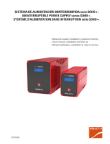
Les agradecemos de antemano, la confianza depositada en nosotros al adquirir este producto. Lean
este manual de instrucciones cuidadosamente antes de poner en marcha el equipo y guárdenlo para
futuras consultas que puedan surgir.
Quedamos a su entera disposición para toda información suplementaria o consultas que deseen realizarnos.
Atentamente les saluda.
Siguiendo nuestra política de constante evolución, nos reservamos el derecho de modificar las características
total o parcialmente sin previo aviso.
Queda prohibida la reproducción o cesión a terceros de este manual, sin previa autorización por escrito por parte
de nuestra firma.
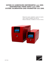
We would like to thank you in advance for the trust you have placed in us by purchasing this equipment. Read
these instructions carefully before starting up the equipment and keep them for any possible future use.
We remain at your entire disposal for any further information or any query you should wish to make.
Thank you.
In our policy of constant evolution, we reserve the right to modify the characterisitcs in part or in whole without
forewarning.
All reproduction or third party concession of this manual is prohibited without the previous written authorisation
of our company.
Nous vous remercions d’avance d’avoir bien voulu déposer votre confiance en nous en acquérant ce
produit. Lisez attentivement ce manuel d’instructions avant de mettre l’équipement en marche puis
conservez le de façon à pouvoir le consulter dans de futures occasions.
Nous restons à votre disposition pour toute information supplémentaire au consultations dont vous
auriez besoin.
Salutations distinguées.
Selon notre politique d’évolution constante, notre firme se réserve le droit de modifier, sans préavis, la totalité ou
une partie des caractéristiques de l’appareil.
La reproduction ou la cession à des tiers du présent manuel est interdite sans l’autorisation préalable par écrit de
notre firme.
SALICRU
SALICRU
SALICRU

- 19 -
General index.
1.- VIEWS OF THE UPS (See figures 5 to 9 in pages 48 to 51).
2.- KEYS TO THE VIEW OF THE UPS.
3.- SAFETY WARNINGS .
3.1.- Points to remember.
3.2.- General warnings.
3.3.- Safety warnings with respect to the batteries.
4.- WORKING PRINCIPLE.
5.- UNIT RECEPTION.
5.1.- Reception and unpacking.
5.2.- Storage.
6.- INSTALLATION.
6.1.- Connection to the mains.
6.1.1.- Connection to the mains of the NX or NX R version.
6.1.2.- Connection to the mains of the NX or NX R version, with the optional "Input polarity detector" (P).
6.2.- Connection of the output (Connection to the loads to be supplied).
6.3.- Connecting to external batteries, connector (4).
6.4.- Connection interface to optocouplers and RS-232.
6.5.- Software.
6.5.1.- Basic structure for installing the "UPSMON" software.
6.5.2.- Hardware Installation.
6.5.3.- "UPSMON" software.
6.5.4.- Software Installation.
7.- STARTING UP AND SHUTTING DOWN THE UNIT.
7.1.- Start-up of the UPS.
7.2.- Shutting down the UPS.
7.3.- From normal working to Bypass and vice versa.
7.4.- Self test function.
7.5.- Cold start.
8.- OPTICAL SIGNALS AND ACOUSTIC ALARMS.
8.1.- Optical signals.
8.2.- Audible alarms.
8.3.- Alarm silence.
9.- FAULT LOCALISATION.
10.- TECHNICAL CHARACTERISTICS.

- 20 -
1.- VIEWS OF THE UPS (See figures 5 to 9 in pages 48 to 51).
2.- KEYS TO THE VIEW OF THE UPS.
(0) IEC input connector.
(1) Input supply pin.
(2) Output bases.
(3) SUB-D9 connector COM port to optocouplers and RS-232.
(4) Connector for external batteries.
(5) Input fuse of magnetic thermal switch.
(6) On / Test / Alarm silencer button.
(7) Off button.
(8) Ventilation grill.
(a) "Line" Led.
(b) "Bypass" Led.
(c) "Inverter" Led.
(d) "Batteries level" Leds bar.
(e) "Load level" Leds bar.
(f) "Overload" Led.
(g) "Fault" Led.
(h) "Low battery" Leds bar.
3.- SAFETY WARNINGS .
3.1.- Points to remember.
• It is essential to comply with the "Safety Instructions", and users are legally responsible for observance. Read the
instructions carefully and follow the indicated steps in the established order.
Local electrical regulations and the different restrictions in the customer’s locality may invalidate certain recom
mendations contained in the manual. Where discrepancies occur, users must comply with all pertinent local regulations.
The instructions and illustrations in this manual are generic for the whole series and are a guide for reference.If
your model does not have any of the described elements, omit all references to them and continue. Furthermore,
the unit is delivered duly identified by etching or labelling, and this must be carefully observed.
• For long periods disconnected, the unit should be connected every four months for at least 6 hours to recharge
the batteries and thus prevent irreversible damage to them. Furthermore, in the event of storage, units must be
placed in a cool, dry placed, never in the open air.
• Do not install the unit in corrosive or dusty atmospheres and never in the open air. Avoid direct sunlight.
• The location must be airy and away from sources of heat, with easy access. Leave a minimum space of 25 cm.
around the unit for the circulation of the ventilation air.
Do not obstruct the ventilation grilles or insert objects through them or through other holes.

- 21 -
• Do not place materials on the unit or elements that might prevent the front from being seen.
• Set up the unit as close as possible to the socket and to the loads to be supplied.
• In cleaning the units, do not use abrasive or corrosive products, liquids or detergents. If you wish to clean the unit,
pass a damp cloth and dry immediately. Avoid splashing or spilling, which might enter slots or ventilation grilles.
• In order to prevent the batteries from discharging completely, and as a safety measure after a long cut in the mains
supply and at the end of the working day, the loads must be shut down, followed by the unit, following the
operation described in the "Instructions Manual ".
• When a fuse has to be replaced, the replacement will be of the same calibre, type and size.
3.2.- General warnings.
• The UPS is a continuous supply unit. If the supply mains disappears when it is running, the output lines still have
voltage, depending on the autonomy given by the battery unit.
• All connections will be performed without mains supply present and with the unit idling.
• The cross sections of the cables used to supply the unit and the loads to be supplied will be in line with the nominal
current indicated on the characteristics plate and adhered to the unit, respecting the Low Voltage Electrotechnical
regulation.
• Pay special attention to the labelling of the unit that warns of the "Danger of electrical discharge " and indicated
as ( ). There are dangerous voltages inside the unit: never open the case, access must only be made by
authorised, competent personnel. In the event of maintenance of breakdown, consult your closest After Sales
Service (A.S.S.).
• The protective ground connection must be made, and always before the input voltage is connected. For small
apparatuses (connected with the cable supplied with a socket pin), users must ensure that the current socket
corresponds to the type supplied, with the ground duly installed and connected to the local protection ground.
For units with terminals, the installer must connect the ground line to the terminal indicated as ( ).
• All electric cables supplying the units and the loads must be fixed to non moving parts to prevent them from being pulled.
• It must be considered that if the unit has a Bypass, with the mains present it will supply voltage to the output
without necessarily being running: Place warning signs and/or emergency switches if the safety regulations of your
specific installation so require.
• RACK-mounted products are intended for installation in a predetermined unit set up by professionals. Their
installation must be planned and carried out by qualified personnel, who will be responsible for applying the
legislation and safety and EMC regulations covering the specific installations in which the product is to be used.
• The batteries generally come as part of the unit, but are exceptionally supplied in an independent case. For the
unit to work optimally, both elements must be placed as closely as possible together without extending the cables
supplied.

- 22 -
3.3.- Safety warnings with respect to the batteries.
• The battery voltage presents a risk of electrocution and may cause high short circuit currents. Before handling,
take the following preventive measures:
- Disconnect the protection elements and make sure the unit is turned off.
- When connecting battery modules to the unit, respect the polarity indicated on the labelling.
- Wear gloves and rubber footwear.
- Use tools with insulated handles.
- Remove all rings, bracelets and other hanging metal objects.
- Do not place tools or metal objects on the batteries.
- Do not short circuit the battery junctions of the unit or possible battery modules, for risk of causing an explosion.
• Do not short circuit the terminals. This is harmful for the unit and for the batteries themselves
• Avoid efforts and mechanical shocks.
• A battery must never be exposed to high temperatures, for risk of explosion.
• Do not break the housing or attempt to open it. The internal electrolyte is toxic and harmful to skin and eyes. In the event
of acid coming into contact with parts of the body, rinse rapidly with abundant water and go to the closest medical service.
• The batteries are a serious hazard for health and the environment and must be eliminated in line with current
regulations.
• When replacing the batteries, use others of the same voltage, capacity and make.
4.- WORKING PRINCIPLE.
The Uninterruptible Power Supply UPS On-Line series NX provide a constant and conditioned voltage to the loads to
be supplied. They protect them against power failure, brown outs, voltage fluctuations, surges and mains interfer-
ence and eliminate any transient before directing the power to the DC Bus. The inverter transforms the DC power into
BYPASS LINE
BATTERIES
FUSE FILTERINVERTERBOOSTER
RECTIFIER
BYPASS
RELE
CHARGER
AC
OUTPUT
AC
INPUT
FILTER
DC CONVERTER
Fig. 1. Block diagram (normal operation).
RELE FILTER
Phase
Neutral

- 23 -
AC voltage supplying a clean output voltages (see Fig. 1).
When an important voltage fluctuation is detected, the UPS switches from normal performance to the autonomy
Fig. 2. Block diagram (Operating on autonomy).
BYPASS LINE
BATTERIES
FUSE FILTERINVERTERBOOSTER
RECTIFIER
BYPASS
RELE
CHARGER
AC
OUTPUT
AC
INPUT
FILTER
DC CONVERTER
RELE FILTER
Phase
Neutral
mode, and the batteries supply the power to the loads (see Fig. 2). As soon as the mains is restored to an acceptable
level, the UPS automatically transfers back to the inverter and will conditionate the power to the equipment by means
of the DC Bus. Batteries will be recharged. During all the operation there is no transfer time from AC voltage to battery
and viceversa.
Furthermore, the batteries charge automatically when the unit is simply connected to the mains, regardless of
whether the UPS is running.
These UPS are designed at high frequency (PWM) without transformer, and are very compact and suitable for any
applications where electronic equipment has to be supplied.
By way of its own protection, the UPS will commute to Bypass in the event of overloading or inverter failure and will
automatically transfer to the inverter when the overload is removed (see Fig. 3).
All UPS may be supplied in a cabinet (NX version), or in rack format (NX R version), and optionally their autonomy
may be extended by battery modules supplied in a metal case, through connector (4).
All devices with the optional "Input polarity detector", are identified with a "P" behind the model.
Fig. 3. Block diagram (Operating on Bypass mode).
BYPASS LINE
BATTERIES
FUSE FILTERINVERTERBOOSTER
RECTIFIER
BYPASS
RELE
CHARGER
AC
OUTPUT
AC
INPUT
FILTER
DC CONVERTER
RELE FILTER
Phase
Neutral

- 24 -
5.- UNIT RECEPTION.
5.1.- Reception and unpacking.
• On receiving the unit, make sure that it has not been damaged in any way during transport, so it is best to unpack
it for a visual inspection and to make sure that its characteristics match those of the order (see the characteristics
plate adhered to the packaging). Otherwise, make all suitable claims to your supplier or, short of this, to our firm,
stating the manufacturing number of the unit and the delivery remittance references.
• Having completed the reception, it is best to pack the UPS once more until it is put into service in order to protect
it against possible mechanical knocks, dust, dirt, etc. In any case, we recommend that you do not discard the
packaging.
• The packing consists of recyclable materials, therefore, if they are to be thrown away, they must be disposed of
in accordance with applicable law.
5.2.- Storage.
• The unit must be stored in a dry premises, well-ventilated and protected from the rain, water projections or
chemical agents. It is best to keep the unit in their original packing as this packing has been specifically designed
to ensure maximum protection during transport and storage.
• The UPS includes sealed lead-calcium batteries except in special cases, and they should not be stored for
more than 4 months without charging the batteries for at least 8 hours. This means that the unit should be connected
to the commercial mains and started. Once the batteries have been charged, it should be returned to its original
packing.
Do not store the apparatuses where the ambient temperature exceeds 40º C or falls under -20º C, as this might
deteriorate the electrical characteristics of the batteries.
6.- INSTALLATION.
• Check the "Safety warnings", see chapter 3.
• Make sure that the data on the characteristics plate are those required for the installation.
• Do not run the UPS when the temperature and humidity exceed the specified limits.
• In the UPS-700 to 1500 NX, make sure that the fuse (5) is in its place and connect the input cable supplied with
the unit to its base (0).
• The unit is supplied through the pluggable cable (1) and it must be connected to a grounded socket, without the
mains present (area contact open).

- 25 -
6.1.- Connection to the mains.
6.1.1.- Connection to the mains of the NX or NX R version.
• The ground connection must necessarily be made, ensuring that this is done before connecting the voltage
to the input of the UPS.
• Connect the input pin (1), to the supply line and without the mains present (area contact open).
6.1.2.- Connection to the mains of the NX or NX R version, with the optional "Input polarity detector" (P).
• The input polarity detector only works on single-phase lines. If a single-phase unit with detector is connected
to a two-phase network, it will not be possible to start it.
• Connect the input plug (1) to an earthed power point, ensuring first of all that it has a network voltage or the
input polarity detector will not be able to verify if it has the right polarity and, consequently, the unit may not start.
- In UPS-700 NX to 1500 NX. The battery LED bar (d) should light up.
- In UPS-2000 NX to 3000 NX and in all rack-version models. Turn the magnetothermic input switch (5) «On» and
the battery LED bar (d) should light up according to the charge level of the batteries.
If, under these conditions, the line LED (a) lights up, it means that the network polarity in the plug (1) is correct.
If, on the other hand, it does not light up, this is a sign that the polarity is wrong. Disconnect the plug (1) from
the network power point, reverse the polarity and check that the LED (a) illuminates.
Note: With the correct input voltage and reversed polarity, by pressing the “On/Test” button (6), the unit will not
start.
6.2.- Connection of the output (Connection to the loads to be supplied).
• Connect the loads to the output bases (2).
• Never connect scanners, laser printers, plotters or any other of high power consuming equipment to the
output sockets (2) as they can overload the equipment.
6.3.- Connecting to external batteries, connector (4).
• All NX series UPS have a connector (4) to optionally increase autonomy by connecting one or more additional
battery modules to the unit. This must only be done in versions with extended autonomy.
Before interconnecting the UPS with the battery module/s, make sure the unit is switched off and the battery
module protection is "OFF". Then connect one end of the cable harness supplied to connector (4) and the other
end to the terminals of the battery module, always respecting the polarity indicated on the labeling and the color
of the cables (red – positive and black - negative).

- 26 -
6.4.- Connection interface to optocouplers and RS-232.
• The interface enables a dialogue between the UPS and the exterior world. Through optocouplers it receives
information on: State of the Network and End of Autonomy. The same connector (3) holds the signals of the RS-232
and a "Shutdown" input that allows the UPS to be able to be turned off when we have a voltage of between 5 and
12 V for more than 500 ms., as long as the mains is absent.
Pin 2. Mains failure. (*)
Pin 4. Optos common. (*)
Pin 5. End of autonomy (approx. <2 min). (*)
Pin 6. +Shutdown and RxD RS-232 (to TxD of the PC).
Pin 7. Shutdown common and RS-232.
Pin 9. TxD RS-232 (to RxD of the PC).
(*) Current and maximum voltage 48 V DC 30 mA non inductive.
• The UPS is supplied with the connection cable and
"UPSMON" software to be installed by the user. Once
the physical connection has been made with the cable between the UPS and the computer, and the software has
been installed, the working system will be intelligent, giving the full protection capacity of the critical loads to be
supplied when the whole installation is working.
Note: The connection of the interface between the UPS and the computer is not implicit to the working of both
units. In the event of making the connection, use only the cable supplied along with the UPS.
6.5.- Software.
6.5.1.- Basic structure for installing the "UPSMON" software.
• PC with a free serial port (COM1 to COM4).
6.5.2.- Hardware Installation.
• Turn off the PC and the monitor.
• Check that the basic structure is at least as indicated in section 6.5.1.
• Connect the cable between the PC (SUB-D9 female) and the UPS (SUB-D9 male). If the serial port in the PC is
a male SUB-D25, use a female SUB-D25 to male SUB-D9 adapter.
• Connect the PC (load) to the UPS, respecting the instructions indicated. Start the PC and the monitor.
• Start the UPS following the instructions in chapter 7. The UPS can be used as a central start – stop unit.
• Before communications can be established between the UPS and the computer, the Config./COM serial port must
be selected and the COM port to which the UPS has been connected. The indicators of the panel of the
"UPSMON" will be visualised, and the parameters and conditions of the UPS will be shown in real time.
Fig. 4. Connector (3) interface SUB D9.
5
6
9
1
6
9
15

- 27 -
6.5.3.- "UPSMON" software.
• The monitoring software is used along with the RS-232 interface to carry out control functions (diagnosis of voltage,
frequency, battery level,...) and facilitate the Shutdown organised by levels in the event of mains failure.
6.5.4.- Software Installation.
• Installation on Windows and Novell Netware.
- Insert the CD-Rom in the corresponding unit of the PC.
- The software installation will boot automatically, but if this property is not activated, just access the unit of the
CD and execute "Setup.exe".
- Follow the steps indicated by the software itself, answering the questions that will appear on the screen.
Note: It is best to perform the installations as the administrator user of the system or with equivalent permits.
7.- STARTING UP AND SHUTTING DOWN THE UNIT.
• Make sure that what is indicated in chapter 6 Installation has been followed.
• Set the battery module protection to "ON", if the unit has extended autonomy.
• Apply mains voltage to the input of the UPS.
• From the very moment that the mains voltage has been applied and the corresponding fuse or the circuit
breaker (5) has been either fitted or turned to the "ON" position, the fans will be in operation and the battery will
be in the charge mode unrelated if the UPS is ON or OFF. The "Batteries level" led bar-graph (d) will show the
batteries level and the "Line" led (a) will indicated that input power is available on the equipment.
7.1.- Start-up of the UPS.
• Press the "ON" (6) for 1 sec., the "Bypass" led (b) will light until the inverter will turn on and the "Inverter" led (c)
will light and the fist one will go off. The UPS's inverter itself takes some seconds to start.
• Turn on the loads, the "Load level" led bar-graph (e) will indicate the persentage of the load level connected to the
output.
• In case of a power failure the "Line" led (a) will go off. An audible alarm will bip every 4 seconds to indicate
batteries are in the discharge mode and besides, by means of "Battery level" led bar-graph (d) it will be possible
to check the estimated % of the available back-up.

- 28 -
7.2.- Shutting down the UPS.
• Press the "OFF" key (7) for 1 second, the inverter will stop supplying output power.
• From the time the commercial supply is applied and the fuse or magnetothermal (5) is fitted or turned to
"ON" respectively, the fans are working and the batteries are loading regardless of whether or not the UPS is
running.
• To completely turn off the UPS, disconnect pin (1) from the network in all fused models, or turn the magnetother-
mal (5) to "OFF" while also turning off the battery module protection if there is one. If is best ot turn off the UPS
completely when it is not expected to be used for a time of over 7 days.
7.3.- From normal working to Bypass and vice versa.
• Under normal conditions with the unit running as in section 7.1, it is the inverter that supplies the loads, and can
force the "Bypass mode", which allows the loads to be supplied directly from the commercial mains.
To pass from normal working to "Bypass mode", press the (6) "ON" and (7) "OFF" keys at the same time for some
5 seconds. An audible beep will sound, the Bypass led (b) will light and the load will be transferred on the Bypass.
To pass from the "Bypass mode" to normal operation, press the (6) "ON" and (7) "OFF" keys at the same time for
some 5 seconds. An audible beep will sound and after some 15 seconds, the load will be transferred on the
inverter.
7.4.- Self test function.
• Use the self test to check the correct performance of the UPS as well as the conditions of the batteries.
• With the mains present and the UPS running, press the button (6) during 3 seconds, during the working operativity,
the UPS will carry a self test which takes about 10 seconds.
Basically this consists in supplying the load or loads from the battery charge is low it returns immediately to the
normal mode. During the process the loads are not affected.
Recharge the batteries for 8 hours and then carry a new self test.
If the process of transferring immediately back to the normal mode is repeated, contact with A.S.S. (After Sales
Service) to replace the batteries.
7.5.- Cold start.
• NX series UPS with the optional "Input polarity detector" (P).
Although these devices can be started up from cold “Cold Start function”, they should never be operated
in this mode without first checking the input polarity. This is because there is a possibility that the input plug (1)
is connected to the network power point in inverted mode, which means that the UPS will be locked at the end
of autonomy.
• Although the unit may be operated in this mode, this is not recommended as it is necessary to take into
consideration the time required to start and shut down the computer, programs and files, compared to the
autonomy made available by the UPS.

- 29 -
8.- OPTICAL SIGNALS AND ACOUSTIC ALARMS.
8.1.- Optical signals.
• "Line" led (a), green. This lights when the line is normal and the input relay has been activated.
It flashes to warn that the input line is off margins.
• "Bypass" led (b), yellow. This lights when the device is in Bypass mode and therefore all of the loads are supplied
from the commercial mains.
• "Inverter" led (c), green. The led lights to indicate that the loads are supplied from batteries through the inverter.
• "Battery level" leds (d), green. The led strip lights from the bottom to the top for the NX version UPS or from left
to right for the NX R version UPS, when a battery charge level is reached of at least: 26, 51, 76 and 91 %
respectively.
• "Charge level" leds (e), green. The led strip lights from the bottom to the top for the NX version UPS or from left
to right for the NX R version UPS, when a charge level is reached of at least: 10, 26, 51 and 76 % respectively.
• "Overload" led (f), red. This lights to indicate that the device is at the limit of its charge capacity.
- Moderate overload (between 105 and 130%). Illuminated LED (f) with intermittent acoustic alarm. It will
transfer shortly to “Bypass mode” and, after a few seconds, will transfer again passing the voltage over the
inverter to verify the voltage level. This process is repeated until the unit’s nominal voltage levels are restored.
- High overload (greater than 130%). Illuminated led (f) with permanent acoustic alarm. It will transfer to “Bypass
mode” until the overload disappears. In the event of a short circuit, the fuse or switch (5) will trip and it will
transfer over the inverter in “autonomy mode”, which, in turn, will effect a shutdown at the output.
- Overload inverter in “autonomy mode”. It automatically effects a shutdown at the output. When the network
is restored, the UPS will reset itself as long as the fuse or switch (5) has not been deactivated.
• "Fault" led (g), red. This is activated when the UPS works incorrectly due to one or several of the following
conditions:
- Inverter failure. On starting according to section 7.1, it is not possible to start the inverter ("Inverter" led (c) out)
and the "Fault" led is activated (g).
- Battery replacement. If the "Fault" led (g) comes on with a battery auto-test, it indicates that the batteries are
faulty. Contact the A.S.S. (After Sales Service).
- Overheating. Under certain extreme conditions, it is possible that the "Fault" led (g) should light due to
overheating, with the consequent risk of the system blocking and therefore a cut in the electricity supply. Shut
down the system, let it cool and start once more.
The following two "Failure" alarms are not identifiable in themselves, but are the result of ignoring the previous
alarms.
- Battery overvoltage, contact the A.S.S. (After Sales Service).
- DC bus failure, contact the A.S.S. (After Sales Service).
• "Low battery" led (h), amber. This lights to indicate that the batteries are at between 10 and 25 % of their capacity
and the Low Battery audible alarm is activated. In the NX R version UPS, this led is grouped to the "Charge level"
led strip and is indicative of the alarm when only this led is alight on the strip.

- 30 -
8.2.- Audible alarms.
• Discharge. Beeps every 4 sec. wiht Led (c) active, to inform loads are supplied from the battery. The alarm stops
upon restoration of the mains supply. If you want to silence the alarm see paragraph 8.3.
• Low battery. Beeps each 0.5 sec. wiht Led (c) active, it indicates the end of autonomy. Shortly the UPS will block
to protect the battery and when the mains returns, the unit will start automatically.
• Overload. Modulated every 0.5 seconds with active LED (f), moderate overload.
Permanent alarm with active LED (f), high overload.
• Replace battery. Continuous alarm wiht the Led (g) lit. Perform self-test as per paragraph 7.4.
8.3.- Alarm silence.
• On the "Autonomy" mode the led (c) lit and (a) turned off an audible modulated, alarm is activated. Press the "ON"
key (6) for 1 second, the "Discharge" alarm will be inhibited. It is not possible to silence any of the other alarms.
9.- FAULT LOCALISATION.
• See table 1.
10.- TECHNICAL CHARACTERISTICS.
Input.
Input voltage AC:................................................................. 100 V (76-130 V); 110 V (80-138 V); 115 V (83,5-140 V);
120 V (87-140 V); 208 V (152-260 V); 220 V (160-276 V);
230 V (167-280 V); 240 V (174-280 V).
Input frequency: .................................................................. 50 Hz or 60 Hz ±5 Hz (auto detection).
Output.
Power depending on model: ............................................... See table 2.
Output voltage on inverter: ................................................. 100 V, 110 V, 115 V, 120 V, 208 V, 220 V, 230 V, 240 V.
Output voltage precision on inverter: ................................. ±2 %, excepting in UPS-3000 NX / NX R to 110 V ±3 %.
Inverter working: .................................................................. PWM (Sine-wave).
Output frequency: ............................................................... 50 Hz or 60 Hz.
Output frequency stability on inverter: ............................... ±0.5 %.
Transfer time: ...................................................................... 0 ms.
Overload detection: ............................................................. 105 % for 10 seconds or 130 % ±10 % for 300 ms..
Harmonic distortion: ............................................................ < 3 % of T.H.D. at linear load.
Efficiency: ............................................................................ > 85 %.

- 31 -
Batteries.
Battery: ................................................................................ Pb-Ca, sealed, maintenance-free.
Recharge time: ................................................................... Approx. 8 hours at 90 % after the end of autonomy.
Autonomy at half load: ....................................................... See table 2.
Battery protection:............................................................... Automatic auto-test and discharge protection, indicator
battery replacement.
Protections and filters.
Input protection: .................................................................. Fuse or magnetic thermal switch, depending on model.
Short circuit protection: ...................................................... Cuts the output voltage immediately or triggering on input
protection.
Table 1. Fault localisation.
(*) A.S.S.: After Sales Service. (**) Only in devices with the optional (P).
PROBLEM CAUSA POSSIBLE ACTION TO TAKE
UPS unable to start, led (a)
out. (**)
UPS unable to start, led (c)
out.
UPS always in "battery dis-
charge" (autonomy mode). Led
(c) active, with acoustic alarm
modulated every 4 sec..
Autonomy excessively short.
Permanent alarm.
Red Led (g) light.
Incorrect input plug (1) polarity. (**)
Pushbutton (6) not activated or pressed for
too short a time.
Low battery voltage.
Failure of the electronic power unit.
Short-circuit or overload on the output of
the UPS.
Input cable not connected.
Triggering of the fuse or MCB switch (5).
Line voltage too high, too low or mains
failure.
Failure of the electronic power unit.
Batteries not fully charged.
Failure of the electronic power unit.
High overload.
See section 8.1, Led "Fault" (g).
Follow the procedure established in sec-
tion 6.1.2. (**)
Press pushbutton (6) as described in
chapter 7.1.
Recharge the UPS for at least 8 h.
Contact A.S.S.. (*)
Shutdown the UPS, verify or reduce
the load and restart the system.
Connect the cable.
Shutdown the UPS. Replace the fuse/
Activate the MCB switch and restart the
system.
Normal condition with mains failure.
Led (a) out or intermittent.
Contact A.S.S.. (*)
Recharge the UPS for at least 8 h.
Contact A.S.S.. (*)
Reduce load.
Depend of the case.

- 32 -
Table 2. Particulars technicals characteristics.
Model. Power. Autonomy at Dimensions. Net weight
(VA / W) half load (min.) Depth x width x heigth (mm). (kg).
UPS-700 NX 700 / 490 15 400 x 145 x 220 8.9
UPS-700 NX R 700 / 490 15 400 x 483 x 130 21.1
UPS-1000 NX 1000 / 700 22 400 x 145 x 220 11.3
UPS-1000 NX R 1000 / 700 22 400 x 483 x 130 23.5
UPS-1500 NX 1500 / 1050 15 400 x 145 x 220 13.9
UPS-1500 NX R 1500 / 1050 15 400 x 483 x 130 26.1
UPS-2000 NX 2000 / 1400 25 460 x 192 x 385 28.1
UPS-2000 NX R 2000 / 1400 25 470 x 483 x 130 27
UPS-3000 NX 3000 / 2100 20 460 x 192 x 385 33.3
UPS-3000 NX R 3000 / 2100 20 470 x 483 x 130 31
Communications.
Interface to optocouplers with information on: ................. Mains failure and end of autonomy.
RS-232:................................................................................ Two-way communication.
Environment.
Dimensions (depth x width x height): ..................................... See table 2.
Net weight: ........................................................................... See table 2.
Working temperature: ......................................................... 0 - 40 ºC.
Humidity:.............................................................................. Up to 95 % without condensation.
Acoustic noise: .................................................................... < 45 dBA at 1 m. for models up to UPS-1500 NX;
< 52 dBA at 1 m. for highers models.
Safety regulation: .............................................................. EN 50091-1.
CEM regulation: ................................................................. EN 50091-2.
Marking: ............................................................................. CE.
Quality: ............................................................................... ISO 9001.

- 49 -
Fig. 7.2.
dh
f
b
e
a
g
c
6
7
{
{
Fig. 7.1.
h
6
a7
bd e g f c a

- 50 -
Fig. 8.1. Posterior / Rear / Vue arrière UPS-700 NX ÷ UPS-1500 NX.
3
5
1
4
0
2
8
Fig. 8.2. Posterior / Rear / Vue arrière UPS-2000 NX ÷ UPS-3000 NX.
3
4
2
5
0
8
1

- 51 -
Fig. 9.2. Posterior / Rear / Vue arrière UPS-2000 NX R ÷ UPS-3000 NX R (Rack).
8
2
3
1
40
5
Fig. 9.1. Posterior / Rear / Vue arrière UPS-700 NX R ÷ UPS-1500 NX R (Rack).
8
2
3
1
4 0
5
/