
SERVICE BULLETIN
SB-6-133-A
Replaces SB-6-133
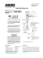
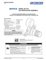
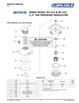
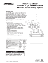
HAR-508 Regulator
Knob
Panel Nut
Bonnet
Maximum Torque
120 in./lbs.
Thrust
Washer
Adjusting
Screw As-
sembly
Main
Spring
*Slip
Ring
*Diaphragm
Assembly
Body
Cover
*Valve
Spring
*Valve
Assembly
Body
Assembly
Bottom Plug
Max. Torque
25 in./lbs.
*Bottom
Plug
O-Ring
* KK-5045 Diaphragm Repair Kit
DESCRIPTION
This unit is designed to regulate and maintain a
nearly constant outlet pressure through the front
and rear 1/4” NPT ports while passing unregulated
air through the 1/2” NPT ports. The front 1/4” port
should be fitted with a gauge (such as a DeVilbiss
GA-316, sold separately) to verify pressure at the
rear 1/4” port.
IMPORTANT: Read and follow all Instructions and
Safety Precautions before installing, operating or
maintaining this equipment. Keep this manual for
future reference.
Risk of explosion or fire.
Improper use can cause personal injury
• This product is designed and intended
for use in industrial compressed air
systems only. Do not use for liquids or
gasses other than air.
• Do not use where pressure or tem-
perature can exceed rated operating
conditions (see specifications).
• Regulated outlet pressure must nev-
er be set higher than the maximum
operating pressure of the downstream
air tool or equipment. An outlet pres-
sure gauge should always be used.
Certain compressor oils, cleaning
agents and solvents may attack the
plastic and rubber components used
in the construction of this product.
This product should not be used in
conjunction with or in the vicinity of
these materials. Read and follow ma-
terial labels carefully. Please consult
DeVilbiss if in doubt.
SPECIFICATIONS
Type Diaphragm, Relieving
Inlet Size 1/2” NPT(F)
Outlet Size (unregulated) 1/2” NPT(F)
Regulated Ports (2) 1/4” NPT(F)
Maximum Inlet Pressure 300 PSIG
Maximum Temperature 175° F (79.4° C)
Flow Specifications Regulated Output
10 CFM @ 45 PSI with 100 PSI inlet
28 CFM @ 60 PSI with 100 PSI inlet

Page 2 SB-6-133-A
WARRANTY
This product is covered by DeVilbiss' 1 Year Limited Warranty.
DeVilbiss Sales and Service: www.devilbiss.com
DeVilbiss
DeVilbiss has authorized distributors throughout the world. For technical
assistance or the distributor nearest you, see listing below.
U.S.A./Canada Customer Service Office:
195 Internationale Blvd., Glendale Heights, IL 60139
Toll-Free Telephone: 1-800-992-4657 (U.S.A. and Canada only)
Toll-Free Fax: 1-888-246-5732
DeVilbiss Automotive Refinishing
DeVilbiss has authorized distributors throughout the world.
For equipment, parts and service, check the Yellow Pages
under “Automotive Body Shop Equipment and Supplies.”
For technical assistance, see listing below.
U.S.A./Canada Customer Service Office:
11360 S. Airfield Road, Swanton, OH 43558
Toll-Free Telephone: 1-800-445-3988 (U.S.A. and Canada only)
Toll-Free Fax: 1-800-445-6643
2/13 ©2013 DeVilbiss All rights reserved. Printed in U.S.A.
INSTALLATION
1. Read all Cautions and Warnings before installing
this unit.
2. Install as close to the point of use as possible. It
is advisable to install a particulate filter on the
inlet side of this product to extend the unit’s ser-
vice life and to minimize the frequency between
necessary maintenance periods.
3. Units must be installed with the free flow in the
direction of the flow arrow. The adjusting knob
may be oriented in any position relative to the
pipe.
4. Avoid using reducing bushings, couplings, etc.,
whenever possible when installing this product.
These devices restrict air flow and can affect
performance.
OPERATION
1. Before turning on system air pressure, turn
adjustment knob full counterclockwise. This
will close regulator to produce zero air pressure.
2. Turn on system air pressure.
3. To increase regulated pressure, pull adjusting
knob up and turn clockwise. To reduce pressure,
turn knob counterclockwise. To lock the knob,
push the knob down.
4. To avoid minor readjustment after making a
change in pressure setting, always approach
the desired setting from a lower pressure.
When reducing pressure, first reduce to some
pressure less than that desired, then bring up to
the desired point.
MAINTENANCE
Do not submerge regulator or components in sol-
vent or use solvent to clean regulator parts. Dam-
age may occur to regulator and components. Use
a cloth dampened in warm, soapy water to clean
exterior of regulator.
Note
This unit may be serviced without removing the unit
from the compressed air line.
1. Frequency of servicing depends largely on the
condition of the compressed air system and the
degree of contamination in the system.
2. Before attempting to service this product in-line,
depressurize both the upstream and downstream
sides of regulator.
3. Remove the bottom plug, valve spring and valve
assembly. Inspect all seals and components for
damage and replace as required. Clean seals
and components with mild detergent and water.
Use a clean, dry cloth to wipe any contamination
from valve seal inside the body. Lubricate the
valve stem and lower valve o-ring seal with a
light coat of MAGNALUBE-G or similar lubricant.
Reassemble. Bottom plug torque should not
exceed 25 in./lbs (2.8 N-m).
4. To replace main spring or diaphragm, turn
adjusting knob counterclockwise to remove all
spring force, then remove bonnet. Remove the
adjusting screw assembly, main spring, slip ring
and diaphragm assembly. Inspect the diaphragm
and the relief seat for damage and contamination.
Replace diaphragm assembly if necessary. Clean
the relief seat with a soft dry cloth. Reassemble in
reverse order making sure the slip ring is properly
positioned on top of the diaphragm. Bonnet
torque should not exceed 120 in./lbs. (13.6 N-m).
5. Before returning unit to service, ensure that all
seals have been properly reinstalled or replaced
and components requiring torque values have
been properly set.
6. If regulated pressure begins to creep (an
uncontrolled rise in regulated pressure), it will
most likely be caused by contamination on the
valve seat.
7. If the unit leaks from the vent holes in the bonnet,
it may be caused by contamination, deterioration
or damage to the valve seat or diaphragm relief
seat. Replace any damaged or worn components.
-
 1
1
-
 2
2


DeVilbiss Air Regulators User manual
- Type
- User manual
- This manual is also suitable for
Ask a question and I''ll find the answer in the document
Finding information in a document is now easier with AI
Related papers
-
DeVilbiss Breathable Air Filtration User manual
-
-
-
 DeVilbiss CleanAir™ Air Line Filters and Control Units User manual
-
 DeVilbiss HAR-600 Air Regulator User manual
-
 DeVilbiss PT-500-WB Service Bulletin
-
 DeVilbiss QM T-5 Series Service Bulletin
-
 Binks Cups & Accessories Owner's manual
-
 DeVilbiss DAD-500™ User manual
-
 DeVilbiss GTi® Suction Feed User manual


Other documents
-
 Binks Air Regulators User manual
-
 Binks Air Regulators User manual
-
 Binks Cups & Accessories User manual
-
 Binks Air Regulators User manual
-
 Binks Air Regulators User manual
-
 Binks Pressure Tanks User manual
-
 Binks Air Regulators User manual
-
DeVillbiss Air Power Company Paint Sprayer AGXV-541 User manual
-
 Binks SG-2 Plus User manual
-
Binks Pressure Cup Outfits User manual


