Page is loading ...

Site Planning
& Installation Guide
3
3M
™
Steri-Vac
™
Sterilizer/Aerator GS Series

2
3M
™
Steri-Vac
™
Sterilizer/Aerator GS Series
Site Planning and Installation Guide
70-2011-5643-0 Issue Date: 10/2015
I. Introduction 3
Device Safety Compliance ������������������������������������������������������������������������������3
EMC Compliance ��������������������������������������������������������������������������������������������4
Plan and Install �����������������������������������������������������������������������������������������������5
II. Select the Equipment 6
III. Select the Location 9
Site Planning Worksheet �������������������������������������������������������������������������������11
Proposed Location of Equipment �������������������������������������������������������������������12
Pre-Installation Visit and Site Readiness Verification ��������������������������������������14
IV. Preparing the Area and Service Requirements 15
Preparing the Selected Area ��������������������������������������������������������������������������15
Utilities ��������������������������������������������������������������������������������������������������������� 15
Electrical Service Requirements ��������������������������������������������������������������������16
Compressed Air Requirements ���������������������������������������������������������������������� 17
Compressor System �������������������������������������������������������������������������������������17
Filters ����������������������������������������������������������������������������������������������������������18
Multiple Sterilizer/Aerator Installations �����������������������������������������������������������18
Compressed Air Line Installation Kit ���������������������������������������������������������������18
Compressor Location �����������������������������������������������������������������������������������18
Ethylene Oxide Vent Line Requirements ���������������������������������������������������������19
3M
™
Abator (Emission Control Devices) ��������������������������������������������������������19
Vent Line Labeling and Install Considerations ������������������������������������������������ 20
Local Exhaust Hood Requirements ��������������������������������������������������������������� 22
Exhaust Ventilation System Planning and Design ������������������������������������������� 22
Exhaust Ventilation System Specifications ���������������������������������������������������� 23
Ductwork ���������������������������������������������������������������������������������������������������� 23
Exhaust Fan ������������������������������������������������������������������������������������������������ 23
Ventilation Failure Detector��������������������������������������������������������������������������� 23
First Aid: Exposure to Ethylene Oxide (EO) �����������������������������������������������������25
Ethylene Oxide Storage ���������������������������������������������������������������������������������25
Requirements for a Vented Cabinet ��������������������������������������������������������������� 26
Connect EO Storage Cabinet to GS Series Sterilizer Dedicated Exhaust ��������� 26
Disposal of 3M
™
Steri-Gas
™
EO Gas Cartridges ����������������������������������������������27
Outside Discharge ����������������������������������������������������������������������������������������27
V. Final Installation and Support 28
Site Readiness Verification ���������������������������������������������������������������������������28
Unpacking the GS Series Sterilizer �����������������������������������������������������������������28
System Checkout and In-Service Training ����������������������������������������������������� 29
VI: Install Guide for 3M
™
In-Wall Mounting Unit 30
General Information ������������������������������������������������������������������������������������� 30
General Specifications ��������������������������������������������������������������������������������� 30
Finished Installation ������������������������������������������������������������������������������������� 30
Finished Wall Specifications ��������������������������������������������������������������������������31
Floor Preparation ������������������������������������������������������������������������������������������31
Installing Permanent Floor Channels ��������������������������������������������������������������31
Placement of 3M
™
Steri-Vac
™
Sterilizer/Aerators onto the Stacking Rack ���������32
Access Area �����������������������������������������������������������������������������������������������32
Installation of Stainless Steel Panels �������������������������������������������������������������32
Stop and Hook Adjustment �������������������������������������������������������������������������� 33
Flexible Connections ������������������������������������������������������������������������������������ 33
Installing the Louvered Panel ����������������������������������������������������������������������� 33
Figure References for Section VI ������������������������������������������������������������������� 34
Notes 43
ANNEX A Symbols, Safety Warnings and Cautions 44
Document Conventions �������������������������������������������������������������������������������� 44
3M
™
Steri-Vac
™
Sterilizer/Aerator GS Series – Explanation of Product and
Packaging Label and Symbols ��������������������������������������������������������������������� 44
3M
™
Steri-Gas
™
EO Gas Cartridges – Explanation of Label and Symbols ��������� 44
Danger �������������������������������������������������������������������������������������������������������� 44
First Aid ������������������������������������������������������������������������������������������������������ 45
Dangers ������������������������������������������������������������������������������������������������������ 45
Warnings ���������������������������������������������������������������������������������������������������� 45
Cautions ����������������������������������������������������������������������������������������������������� 45
ANNEX B Worksheets 46
Site Planning Worksheet ������������������������������������������������������������������������������ 46
Equipment Location Worksheet ���������������������������������������������������������������������47
ANNEX C Site Readiness and Installation Verification Forms 48
Site Readiness Verification Form ����������������������������������������������������������������� 48
Installation Verification Form ������������������������������������������������������������������������ 49
ANNEX D 3M
™
Steri-Gas
™
EO Gas Cartridge Dilution Charts 50
ANNEX E Bibliography and Compliance References 51
Equipment and Ethylene Oxide (EO) Compliance Documents ��������������������������51
ANNEX F Disposal of Packaging 51
Contact Information ��������������������������������������������������������������������������������������52
Table of Contents

3
70-2011-5643-0 Issue Date: 10/2015
3M
™
Steri-Vac
™
Sterilizer/Aerator GS Series
Site Planning and Installation Guide
I� Introduction
This Site Planning and Installation Guide is intended to provide information for prospective and new
purchasers of the 3M
™
Steri-Vac
™
Sterilizer/Aerator GS Series, in order to help plan for and execute
site and installation requirements�
The purchaser is responsible for providing required GS Series sterilizer service requirements to the
area where the equipment will be installed� These services include electricity, compressed air,
and an ethylene oxide (EO) vent line� A dedicated exhaust system is required for installing the
3M
™
Steri-Vac
™
Exhaust Hood option�
The purchaser is responsible for installing the GS Series sterilizer and accessory equipment
in their permanent location and to connect the required services to the unit(s)� The purchaser
is also responsible for ensuring that all national, state and local code requirements are met
(e�g�, EO abatement, state of California seismic bracing, etc�)� At the time of installation, 3M Health
Care service personnel or authorized 3M service personnel will require written documentation to
verify the requirements for room ventilation and non-recirculating ventilations systems are met�
See ANNEX A for a complete listing of symbols, safety warnings and cautions�
Device Safety Compliance
The 3M
™
Steri-Vac
™
Sterilizer/Aerator GS Series is an instrument and Class II medical device per the
U�S� Food and Drug Administration (FDA) classification definitions� It is a Class IIb medical device per
the European Union Medical Device Directive (MDD) and carries a CE mark related to the Medical
Device Directive 93/42/EEC as confirmed in the Declaration of Conformity�
The 3M
™
Steri-Vac
™
Sterilizer/Aerator GS Series is listed as Laboratory Electrical Equipment for Use
in Health Care Applications and carries the UL mark with adjacent indicators “C” and “US” based on
compliance to the standards UL 61010-1 and CAN/CSA 22�2 No� 61010-1�
The 3M
™
Steri-Vac
™
Sterilizer/Aerator GS Series is designed, manufactured, and tested to meet
the safety and performance requirement of common safety codes and standards which include
applicable portions of the following standards demonstrated by the CB Scheme Certificate and
test report issued by Underwriters Laboratories (UL):
• IEC/EN 61010-1� Safety requirements for electrical equipment for measurement, control, and
laboratory use - Part 1: General requirements�
• IEC/EN 61010-2-010� Safety requirements for electrical equipment for measurement, control
and laboratory use - Part 2-010: Particular requirements for laboratory equipment for the heating
of materials�
• IEC/EN 61010-2-040� Safety requirements for electrical equipment for measurement, control,
and laboratory use - Part 2-040: Particular requirements for Sterilizer/Aerators and washer-
disinfectors used to treat medical devices�
• RoHS Directive, Directive 2011/65/EU of the European Parliament and of the Council on the
restriction of the use of certain hazardous substances in electrical and electronic equipment�
CAUTION
To reduce the risk of injury, always follow the
procedures described in this Site Planning and
Installation Guide�

4
70-2011-5643-0 Issue Date: 10/2015
3M
™
Steri-Vac
™
Sterilizer/Aerator GS Series
Site Planning and Installation Guide
Note: This equipment has been tested and found
to comply with the limits for a Class A digital device,
pursuant to Part 15 of the FCC Rules� These limits are
designed to provide a reasonable protection against
harmful interference when the equipment is operated
in a commercial environment� This equipment
generates and can radiate radio frequency energy
and, if not installed and used in accordance with this
document and the 3M
™
Steri-Vac
™
Sterilizer/Aerator
GS Series Operator Manual, may cause harmful
interference to radio communications� Operation of
this equipment in a residential area is likely to cause
harmful interference in which case the purchaser
will be required to correct the interference at their
own expense� In addition, operation of this device
may accept any interference received, including
interference that may cause undesired operation�
EMC Compliance
The 3M
™
Steri-Vac
™
Sterilizer/Aerator GS Series complies with the following EMC standards as
confirmed in the Certificate of Compliance generated by 3M:
• IEC 61326-1� Electrical equipment for measurement, control and laboratory use - EMC requirements
- Part 1: General requirements�
• EMC requirements of the CE mark EMC Directive 2004/108/EC�
• Australian EMC requirements as confirmed in the Supplier’s Declaration of Conformity that is linked
to the RCM Mark�
• As a Class A digital apparatus meeting all requirements of the Canadian Interference-Causing
Equipment Regulations�
See ANNEX E for a complete list of related compliance standards for the 3M
™
Steri-Vac
™
Sterilizer/Aerator GS Series�
I� Introduction (continued)

5
70-2011-5643-0 Issue Date: 10/2015
3M
™
Steri-Vac
™
Sterilizer/Aerator GS Series
Site Planning and Installation Guide
Plan and Install
The following describes the tasks for planning and preparing for a successful installation� While each
installation site is unique, the following steps are common to all situations:
3M offers a complete system of products for ethylene oxide (EO) sterilization, including two sizes of
3M
™
Steri-Vac
™
Sterilizer/Aerator GS Series� Both sizes are available in single door or double door
configurations� Use the 3M
™
Abator, where applicable, for efficient abatement of exhausted EO and for
using supporting accessory equipment� Selecting the size, quantity and configuration of the GS Series
sterilizer and the number of 3M
™
Abators is the first equipment selection task� Second, select any
required auxiliary equipment� Additional detailed equipment technical specification information for the
products is available from 3M� Use Table 1 on the following page to document selected equipment�
Step 2 recommends a process for analyzing a site and for selecting a suitable location for installing the
Sterilizer/Aerator system� This Guide includes sample proposed site plans, with architectural details,
for a satisfactory site design� It also includes information on how to design the site� Site Planning and
Equipment Location Worksheets are provided in ANNEX B�
Critical service requirements must be met before completing and approving the 3M
™
Steri-Vac
™
Sterilizer/Aerator GS Series Site Readiness Verification Form� These requirements include acceptable
room ventilation, connections to electrical power, connections to vent lines, and compressed air lines�
Service requirements are detailed in Section III�
The purchaser is responsible for securing and scheduling all contracted services in order to meet
installation requirements and for supplying details of the service requirements to the contractors�
The final installation support visit will not be scheduled until all equipment installation requirements
have been met, verified, and documented on the Site Readiness Verification Form found in ANNEX C�
Sections II and III provide information detailing service specifications and requirements� ANNEX B
provides Site Planning and Equipment Location Worksheets� This information can be reproduced
and provided to service contractors, as necessary, to complete the required pre-installation work�
Deviations from the Site Plan:
The purchaser should document any deviations from the recommended 3M Site Planning guidance
and communicate the deviations to 3M Health Care service personnel or authorized 3M service
personnel prior to installation�
Final equipment hook-up and installation support is performed by 3M Health Care service personnel
or authorized 3M service personnel� A final Installation Verification Form is completed at the end of
equipment installation�
Site planning is a critical aspect for a successful
installation process� Site planning includes
considerations for: the location, the work flow,
the 3M
™
Steri-Vac
™
Sterilizer/Aerator GS Series
service requirements, 3M
™
Steri-Gas
™
EO Gas
Cartridge storage requirements both near the GS
Series sterilizer and storage for larger volumes, any
connected hardware such as the 3M
™
Abator,
3M
™
Stacking Rack 1237, ventilation apparatuses,
and local code requirements� The purchaser must
comply with all state and local regulations affecting
the use of ethylene oxide (EO)� It is important
to have a properly planned and acceptably
prepared site to ensure the GS Series sterilizer
operates safely and effectively� All site planning
and preparation must be completed prior to the
scheduled installation date�
Step 1 Select the Equipment
Step 2 Select a Location
Step 3 Prepare the Area and Service Requirements
Step 4 Install the Equipment
I� Introduction (continued)

6
70-2011-5643-0 Issue Date: 10/2015
3M
™
Steri-Vac
™
Sterilizer/Aerator GS Series
Site Planning and Installation Guide
Table 1 provides the complete listing of 3M
™
Steri-Vac
™
Sterilizer/Aerator GS Series products and
accessories equipment� This Table provides product descriptions, dimensions and other information
that is important to consider in equipment selection� 3M Sales and Service personnel will consult and
assist in selecting the appropriate equipment in order to meet specific facility and use requirements�
See Figure 1 for GS5 dimensions and elevations� See Figure 2 for GS8 dimensions and elevations�
Table 1 – 3M
™
Steri-Vac
™
Product and Accessory Options
Product Description
Shipping
Weight
Operational
Weight
Chamber Size
Exterior
Dimensions
Select
Quantity
Area H × W × D H × W × D
3M
™
Steri-Vac
™
Sterilizer/Aerator
GS5
Single Door – EO
Sterilizer/Aerator
163 kg
(359 lbs)
Single Door
127 kg
(281 lbs)
Single Door
136 L
(4�8 cubic
feet)
38 × 43 × 83 cm
(15 × 17 × 32�5 in)
70�9 × 76�2 × 95�0 cm
(27�9 × 30�0 × 37�4 in )
3M
™
Steri-Vac
™
Sterilizer/Aerator
GS5
Double Door – EO
Sterilizer/Aerator
169 kg
(373 lbs)
Double Door
132 kg
(290 lbs)
Double Door
3M
™
Steri-Vac
™
Sterilizer/Aerator
GS8
Single Door – EO
Sterilizer/Aerator
355 kg
(782 lbs)
Single Door
261 kg
(576 lbs)
Single Door
223 L
(7�9 cubic
feet)
46 × 51 × 97 cm
(18 × 20 × 38 in)
179�8 × 94�0 × 109�0 cm
(70�8 × 37�0 × 42�9 in)
3M
™
Steri-Vac
™
Sterilizer/Aerator
GS8
Double Door – EO
Sterilizer/Aerator
362 kg
(799 lbs)
Double Door
267 kg
(593 lbs)
Double Door
3M
™
Abator
Models 50, 50AN,
50AE
Emission
Control System
212 kg
(469 lbs)
163 kg
(360 lbs)
NA
80�0 cm × 82�0 × 105�0 cm
(31�0 × 32�0 × 41�0 in)
3M
™
Steri-Vac XL
Aerator (outside U�S�
only for health care)
Single Door
Aerator
147 kg
(325 lbs)
Single Door
115 kg
(253 lbs)
Single Door
141�5 L
(4�5 cubic
feet)
38 × 43 × 83 cm
(15 × 17 × 32�5 in)
61�0 x 77�0 x 89�0 cm
(24�0 x 30�3 x 35�0 in)
3M
™
Steri-Vac XL
Aerator (outside U�S�
only for health care)
Double Door
Aerator
156 kg
(345 lbs)
Double Door
124 kg
(273 lbs)
Double Door
Product Part Number Description
Dimensions
H × W × D
Select
Quantity
Extra Baskets
GS5 and XL Aerator
78-8055-6040-2 Stainless lower basket 39 × 80 × 18 cm (15�5 × 31�5 × 7 in)
78-8055-6039-4 Stainless upper basket 39 × 80 × 18 cm (15�5 × 31�5 × 7 in)
Extra Baskets
GS8
78-8078-8313-3 Stainless steel lower basket 47 × 95 × 20 cm (18�5 × 37�5 × 8 in)
78-8078-5399-5
Stainless steel upper half basket
47 × 47 × 20 cm (18�5 × 18�5 × 8 in)
78-8078-6251-7 Stainless steel basket cover
Cover fits on top of lower basket
Note: Equipment may vary in overall exterior dimensions if accessories (e�g� exhaust duct, leveling
feet) are added�
II� Select the Equipment
Factors to consider in
equipment selection:
• Chamber size related to processing volume
requirements, including future volume
requirements
• Single door or double door configuration based
on process flow and available space
• National, state, and local requirements for
ethylene oxide (EO) abatement as applicable
• 3M
™
Steri-Vac
™
EO Gas Cartridge type, volume
and storage requirements� A vented liquid
flammable storage cabinet is required for
EO gas storage� See Section III for additional
information�

7
70-2011-5643-0 Issue Date: 10/2015
3M
™
Steri-Vac
™
Sterilizer/Aerator GS Series
Site Planning and Installation Guide
Figure 1. 3M
™
Steri-Vac
™
Sterilizer/Aerator GS Series, Model GS5
Single Door Dimensions
30�5 cm
(12 in�)
76�2 cm
(30 in�)
70�9 cm
(27�9 in�)
47�6 cm
(18�75 in�)
95 cm
(37�4 in�)
50�2 cm
(19�8 in�)
52 cm
(20�5 in�)
44�2 cm
(17�4 in�)
26�6 cm
(10�5 in�)
7�6 cm
(3 in�)
7�6 cm
(3 in�)

8
70-2011-5643-0 Issue Date: 10/2015
3M
™
Steri-Vac
™
Sterilizer/Aerator GS Series
Site Planning and Installation Guide
Figure 2. 3M
™
Steri-Vac
™
Sterilizer/Aerator GS Series, Model GS8 Single Door
Dimensions and Elevations
Front Elevation
Plan View
Unload Side
Load Side
Side Elevation
3�2 cm
(1�25 in�)
clearance
between floor
and bottom
of Side and
Front Panels
Unload Side
(two door)
66 cm
(26 in�)
61�0 cm
(24 in�)
109�2 cm
(42�9 in�)
94�0 cm
(37 in�)
179�8 cm
(70�8 in�)
From
Ground
31�8 cm
(12�5 in�)
54�6 cm
(21�5 in�)
7�6 cm
(3 in�)
88�9 cm
(35 in�)
92�7 cm
(36�5 in�)
109.2 cm
(43 in.)
72�4 cm
(28�5 in�)
54�6 cm
(21�5 in�)
Power
Vent Line
Compressed Air

9
70-2011-5643-0 Issue Date: 10/2015
3M
™
Steri-Vac
™
Sterilizer/Aerator GS Series
Site Planning and Installation Guide
Give careful consideration in selecting the location for the 3M
™
Steri-Vac
™
Sterilizer/Aerator GS
Series and accessories in order to ensure that facility, compliance, and safety requirements are met�
This section provides information on requirements that the equipment location must meet related to
Recommended Environmental Operating Specifications (Table 2), occupational safety, and work flow
aspects� Prior to installation, 3M Health Care service personnel or authorized 3M service personnel
will request written verification that the requirements for the general room ventilation rate and the
non-recirculating ventilation system, as described in this Guide and documented on the Site Readiness
Verification Form, are met (see ANNEX C)� At the time of installation, 3M Health Care service
personnel or authorized 3M service personnel will require the purchaser's requirements document and
verification in writing stating that the requirements for general room ventilation rate, non-recirculation,
and dedicated system requirements are met�
Table 2 – Recommended Environmental Operating Specifications
Environmental Condition Condition Range Units
Altitude 2500 (max) Meters
Operating Temperature* 15–35 °C
Humidity 20–80 (non-condensing) % RH
Voltage Range (Frequency)
Single Phase
200–240 (50/60) VAC (Hz)
Current: GS5
GS8
7
12
A
A
Transient Over Voltages Category II N/A
Pollution Degree 2 N/A
* Operating the 3M
™
Steri-Vac
™
Sterilizer/Aerator GS Series in a temperature environment that is close to the sterilization
process temperature set point (e�g� 35ºC operating environment and a 38ºC sterilization process temperature set point)
may result in a temperature fault during the sterilization process�
Note: Verify the requirements and follow all applicable national, state, and local environmental
regulations concerning proper installation of the GS Series sterilizer and any 3M
™
Abator for control
of ethylene oxide (EO) emissions� It is important to place the sterilizer in a contained area, with traffic
routed around or away from the area, and restricted personnel access� The size of the area should
be 30 m
3
(1000 ft
3
), or more, and have a minimum of 10 air exchanges per hour� Do not place the
sterilizer or 3M
™
Steri-Gas
™
EO Gas Cartridges in an area of possible ignition sources�
III� Select the Location
WARNING
To reduce the risk of shock due to
hazardous voltage, do not operate the
3M
™
Steri-Vac
™
Sterilizer/Aerator GS Series
outside the environmental conditions as
stated in this Guide�
DANGER
To reduce the risks associated with
exposure to ethylene oxide:
Ensure a minimum of ten (10) air exchanges
per hour (ACHs) for the room in which the
3M
™
Steri-Vac
™
Sterilizer/Aerator GS Series
is installed�
Do not operate the 3M
™
Steri-Vac
™
Sterilizer/
Aerator GS Series outside the environmental
conditions as stated in this Guide�
Ensure the instructions detailed in this
Guide are followed when planning the
ventilation system�

10
70-2011-5643-0 Issue Date: 10/2015
3M
™
Steri-Vac
™
Sterilizer/Aerator GS Series
Site Planning and Installation Guide
An appropriate selected location must meet all of the following requirements� The location:
• has no flammable gases other than ethylene oxide (EO) present at the location�
• is not a high traffic area�
• is well-ventilated with at least 10 air changes per hour� The flow of air is away from the equipment
operator (Figure 3)� Recommended room size is a minimum of 28�32 m
3
(1,000 ft
3
)�
• has a non-recirculating ventilation system� The exhaust hood, if used, must be connected to an
exhaust system that is dedicated to the 3M
™
Steri-Vac
™
Sterilizer/Aerator GS Series area and
supplies air flow >125 cubic feet per minute (CFM) through each vent hood�
• allows 51 cm (20 inches) of clearance space at the top, rear, and sides of the GS Series sterilizer
for maintenance and service (Figure 5)�
• provides a suitable location for storage of 3M
™
Steri-Gas
™
EO Gas Cartridges that includes a
flammable liquids cabinet vented to the outside�
Appropriate installation of the air handling system is important and should be designed and installed
to provide air flow through the entire room and direct air movement away from the GS Series sterilizer
and Operator as shown in Figure 3�
Figure 3. Example of Acceptable and Unacceptable Air Flow
Acceptable Air Flow Unacceptable Air Flow
Exhaust
Exhaust
Sterilizer Sterilizer
"Dead" Air Space
Exhaust
Intake
Intake
or
Air flow washes entire room�
Air movement is away from operator�
Air movement is toward operator and
"dead" air spaces can form�

11
70-2011-5643-0 Issue Date: 10/2015
3M
™
Steri-Vac
™
Sterilizer/Aerator GS Series
Site Planning and Installation Guide
Site Planning Worksheet
It may be helpful to use the provided Site Planning Worksheet (ANNEX B) to sketch the architectural
details of the location where the equipment will be installed� Include all details, such as walls,
doorways, structural supports, ventilation ducts (intake and exhaust), and electrical outlets (Figure 4)�
Indicate any equipment that will be removed� The blank worksheet can be duplicated by the purchaser�
Figure 4. Site Planning Example
Equipment to be removed

12
70-2011-5643-0 Issue Date: 10/2015
3M
™
Steri-Vac
™
Sterilizer/Aerator GS Series
Site Planning and Installation Guide
Proposed Location of Equipment
Using the completed sketch on the Site Planning Worksheet, complete an Equipment Location
Worksheet (ANNEX B) to show the location and size of each piece of equipment in the work area
(Figure 5)� Include all other hard good items in the room (e�g� work tables, storage cabinets, etc�),
as this will help to assess the work flow�
After placing the 3M
™
Steri-Vac
™
Sterilizer/Aerator GS Series and any accessory equipment on the
Equipment Location Worksheet, indicate on the Worksheet any additional services required for the new
equipment� Provide the worksheets and service requirements to any contractors (electrical, ventilation,
plumbing, and structural) involved with the project�
Figure 5. Work Area and Equipment Location Example
CAUTION
To reduce patient risks associated with
exposure to potentially non-sterile devices
or inadequate sterilization procedures, do not
install 3M
™
Steri-Vac
™
Sterilizer/Aerator GS Series
near any device emitting strong electronic magnetic
fields (EMFs)�
Abator
Indicator
Panel
Abator
Indicator
Panel
EO STERILIZER AND
OPERATOR ROOM
SERVICE
ROOM
GS8
GS5 above
GS5
below
Prep Table
Exhaust Vent
Cart
Flammable
Liquid
Storage
Cabinet
Prep Table
Abator
Abator
10 cm
(4 in�)
CLR
10 cm
(4 in�)
CLR
51 cm
(20 in�)
CLR
51 cm
(20 in�)
CLR
51 cm
(20 in�)
CLR
51 cm
(20 in�)
CLR
51 cm
(20 in�)
CLR
51 cm
(20 in�)
CLR
Prep Table

13
70-2011-5643-0 Issue Date: 10/2015
3M
™
Steri-Vac
™
Sterilizer/Aerator GS Series
Site Planning and Installation Guide
The 3M
™
Steri-Vac
™
Sterilizer/Aerator GS Series, Model GS5 can be installed in-wall or installed and
used with a 3M
™
Stacking Rack Model 1237 as shown in Figure 6� The 3M
™
Steri-Vac
™
Sterilizer/
Aerator GS Series, Model GS8 is typically installed in-wall (Figure 7)�
Figure 6. Typical In-wall Opening Requirements for 3M
™
Steri-Vac
™
Sterilizer/
Aerator GS Series, Model GS5
195�0 cm
(77 in�)
106�7 cm
(42 in�)

14
70-2011-5643-0 Issue Date: 10/2015
3M
™
Steri-Vac
™
Sterilizer/Aerator GS Series
Site Planning and Installation Guide
Figure 7. Typical In-Wall Opening Requirements for 3M
™
Steri-Vac
™
Sterilizer/
Aerator GS Series, Model GS8
Pre-Installation Visit and Site Readiness Verification
Prior to the installation of the 3M
™
Steri-Vac
™
Sterilizer/Aerator GS Series and any other accessory
equipment, the 3M Health Care service personnel or authorized 3M service personnel can be
contacted to visit the facility where the equipment will be installed� The proposed Site Planning and
Equipment Location Worksheets must be reviewed to discuss the required services, equipment
spacing, and any additional considerations� A Site Readiness Verification Form (ANNEX C) must be
completed and documented with the purchaser�
188�0 cm (74 in�) Max�
182�9 cm (72 in�) Min�
111�8 cm (44 in�) Max�
104�1 cm (41 in�) Min�
114�3 cm (45 in�)
Min� Depth
114�3 cm
(45 in�)
189�2 cm
(74�5 in�)
108�0 cm
(42�5 in�)

15
70-2011-5643-0 Issue Date: 10/2015
3M
™
Steri-Vac
™
Sterilizer/Aerator GS Series
Site Planning and Installation Guide
Preparing the Selected Area
Once the location is selected and designed, the next step is to prepare the area� This section provides
details on the basic service connections required for the 3M
™
Steri-Vac
™
Sterilizer/Aerator GS Series
and accessory equipment� Additional services may be needed for other equipment installed in order to
support the GS Series sterilizer equipment�
The following equipment is needed to prepare the area:
• An air compressor to supply clean, dry, oil-free
air for the sterilizer vacuum system�
• If required by national, state, or local regulations
or facility/company policy, an ethylene oxide
(EO) emission control system�
• A ventilation system connection to local exhaust
hoods (as applicable)�
• Ethernet connection for service and other
electronic interfaces�
Utilities
Consider the placement of utility services required for additional equipment� Obtain documentation
from supplier(s) for additional non-3M equipment and understand and implement all applicable
installation and service requirements for this equipment�
Table 3 provides detailed information for contractors installing the utilities and services that are required
to safely use the 3M
™
Steri-Vac
™
Sterilizer/Aerator GS Series and accessory equipment� This Guide,
or individual pages from this Guide, can be photocopied and provided to contractors involved with the
project� The information, figures, and project worksheets are intended to provide examples of before
and after installation of the equipment in order to provide contractors with an understanding of the
project scope and requirements� Figure 8 shows typical service connections for the GS Series sterilizer�
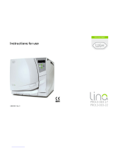
Figure 8. Typical Service Connections for the GS Series Sterilizer, Model GS8
23�0 cm
(58�42 in�)
22�5 cm
(57�15 in�)
26�0 cm
(66�04 in�)
31�75 cm
(80�65 in�)
Note: The 3M
™
Steri-Vac
™
Sterilizer/Aerator
GS Series will remain locked for three (3) hours
for mandatory aeration without a connected and
operational local exhaust hood�
IV� Preparing the Area and Service Requirements

16
70-2011-5643-0 Issue Date: 10/2015
3M
™
Steri-Vac
™
Sterilizer/Aerator GS Series
Site Planning and Installation Guide
WARNING
To reduce the risks associated with fire
and explosion, purchaser must comply with
applicable codes and regulations as they pertain
to locating the equipment and providing services
to the equipment�
WARNING
To reduce the risk of shock due to
hazardous voltage, purchaser must provide
a properly grounded outlet (an earth ground) for
installation, per applicable codes and regulations�
Electrical Service Requirements
The electrical service requirements for the installed 3M equipment are shown in Table 3� Be sure to
provide sufficient access to the power disconnect and switch� When planning the electrical service,
consider support equipment including: compressors, air dryers, and emission control systems�
Table 3 – Electrical Service Requirements
Requirement GS5 Sterilizer/Aerator GS8 Sterilizer/Aerator
Voltage 200–240 Vac
Frequency 50/60 Hz
Phase Single
Current 15 amp dedicated circuit
Heat Load 5500 Btu/hr 6150 Btu/hr
Internal Circuit Breaker 7 amp 12 amp
Power Cord 240 volt, 15 amp, NEMA 6-15 plug
2
Marks FCC cULus RCM CE0086 FCC cULus RCM CE
Code and Building
Regulation Compliance
Due to variation in local regulations, the purchaser is responsible for complying
with applicable codes and regulations as they pertain to locating the equipment
and providing services to the equipment�
Seismic Bracing
Seismic Bracing kits for 3M
™
Steri-Vac
™
Sterilizer/Aerator GS Series, Models GS5
and GS8 units are available from 3M� For information on the State of California
pre-approved seismic bracing certificates, contact 3M�
UL listed to U�S� and Canadian Safety Standards
RCM Compliant with all applicable regulatory arrangements (RCM)
FCC (Federal Communication Commission)
Conformity to European Directives

17
70-2011-5643-0 Issue Date: 10/2015
3M
™
Steri-Vac
™
Sterilizer/Aerator GS Series
Site Planning and Installation Guide
Compressed Air Requirements
Compressed air is used to operate a venturi vacuum generator and to operate the air-controlled pistons
that both lock and unlock the 3M
™
Steri-Vac
™
Sterilizer/Aerator GS Series door� Table 4 provides
the compressed air requirements� The vacuum operates during the sterilization cycle to remove air
and ethylene oxide (EO) from the GS Series sterilizer chamber� The vacuum also operates during the
Aeration stage, which may last in excess of 12 hours�
Moisture in the compressed air line will not be removed by the supplied filter� A refrigerated air dryer
may be needed to meet the dew point requirement in Table 4 and should be a non-cycling hermetic
type compatible with the flow and pressure of the selected compressor� The air dryer should be
capable of accepting saturated air and drying it to 10°C (50°F) dew point at 38°C (100°F) ambient�
The air dryer would typically have an automatic drain trap and be wired from the compressor controller�
Table 4 – Compressed Air Specifications
Specifications
Value/Range
Pressure
7�0 kg/cm
2
(100 psig) minimum
10�5 kg/cm
2
(150 psig) maximum
Flow Rate
2�2 liters per second at 5�6 kg/cm
2
(4�7 cubic feet per minute at 80 psig)
per Sterilizer/Aerator based on 100% duty cycle compressor
Quality Clean air supply with a maximum allowable dirt particle size of 0�5 microns and free of oil
Moisture Content Less than 10°C (50°F) dew point
If the compressed air source does not meet the specifications, it can cause early equipment failures�
The GS Series sterilizer warranty and preventive maintenance agreements do not cover equipment
failures caused by an improper compressed air source� Contact the 3M Health Care Service Center or
your local 3M office for additional information regarding warranty and preventative maintenance plans�
The following refrigerated air dryer is an example of equipment that may be used:
Model: Arrow F-10
Supplier: Arrow Dryers
Website: www�arrowpneumaticdryers�com
Telephone (U�S�): 1-800-761-4298
Compressor System
The following recommended compressor manufacturer can provide additional information about
compatible compressor systems:
Supplier: Powerex
Website: www�powerexcompressors�com
Telephone (U�S�): 1-800-761-4298
DANGER
To reduce the risks associated with
exposure to ethylene oxide, ensure
compressed air supply is clean, with a maximum
allowable dirt particle size of 0�5 microns, and
oil-free� Ensure air filters on compressed air
supply contain a water trap and are cleaned
and maintained properly�
Outside of the U�S�, contact your local 3M Health Care
service personnel or authorized 3M service personnel
for local suppliers of equipment that meets the
required specification�

18
78-0803-3481-3 – Rev A� Issue Date: 8/2015
3M
™
Steri-Vac
™
Sterilizer/Aerator GS Series
Site Planning and Installation Guide
Filters
A 3M air line filter kit is needed and supplied with each 3M
™
Steri-Vac
™
Sterilizer/Aerator GS Series to
remove dirt and mist particles from the incoming air� This filter must be installed on the compressed
air line at the time of equipment installation and must be drained periodically by the purchaser in order
to remove excess water� These filters are replaced at each recommended six month preventative
maintenance service procedure�
The installation includes installing the 0�3 micron filter element (mist separator) in front of the
0�1 micron filter element (micro mist separator) in order to remove coarse air contaminants that would
otherwise plug the micro-mist element� The elements may need to be changed more frequently than
six month intervals if the air supply is highly contaminated�
The purchaser is solely responsible for providing a dry, oil-free air supply (to a dew point of 10°C/50°F)�
Filters are provided for precautionary purposes only, and not as a replacement for a clean air supply�
A contaminated air supply can quickly reduce the effectiveness of the filter element, resulting in early
equipment failure�
Multiple Sterilizer/Aerator Installations
Each 3M Steri-Vac GS Series sterilizer requires a minimum flow rate of 2�2 liters per second
(4�7 scfm) at 5�6 kg/cm
2
(80 psig) pressure� Two sterilizers would require a flow rate of
4�4 liters per second (9�4 scfm) air flow at 5�6 kg/cm
2
(80 psig)�
Compressed Air Line Installation Kit
The Compressed Air Line Installation Kit, supplied with each GS Series sterilizer, is installed between
the sterilizer and the compressed air services as shown in Figure 9� The purchaser is responsible for
providing compressed air services�
Compressor Location
The compressor should be located away from work areas in order to reduce noise levels around the
GS Series sterilizer� Make sure the compressor manufacturer’s electrical power requirements are met�
Figure 9. Compressed Air Line Connection Details
(Using Installation Kit)
1
⁄4" NPT × �625 Tube Adapter
1
⁄4" NPT, 90° Street Elbow
1
⁄4" Hex Nipple
1
⁄4" Hex Nipple
1
⁄4" NPT TO
1
⁄4" NPT
2" Long
Nipple
7' High Pressure
Flex Air Line
1
⁄4" NPT
×
1
⁄4" NPT
90° Elbow
1
⁄4" NPT
Union
3
⁄8" NPT Bushing
1
⁄4" Tee
Flow
Shut Off Valve
Micro Mist Separator
Sterilizer
0–160
PSI
Gauge
Mist Separator
Optional
If required
(Included
in kit)

19
70-2011-5643-0 Issue Date: 10/2015
3M
™
Steri-Vac
™
Sterilizer/Aerator GS Series
Site Planning and Installation Guide
Ethylene Oxide Vent Line Requirements
A connection must be made from the 3M
™
Steri-Vac
™
Sterilizer/Aerator GS Series to a dedicated vent
line in order to exhaust ethylene oxide (EO) to the outside atmosphere or to the 3M
™
Abator emission
control system� The requirements for venting the GS Series sterilizer must be met (Table 5)�
Table 5. Vent Line Requirements for GS Series
Number of Sterilizer per Abator
Length and Diameter of Vent Line
1
Length
≤ 31�0 m
(100 ft�)
31�1 m to ≤
61�0 m (200 ft�)
61�1 m to ≤
91�5 m (300 ft�)
Diameter
2�54 cm
(1 in�)
2�54 cm (1 in�) 2�54 cm (1 in�)
2
Length
≤ 31�0 m
(100 ft�)
31�1 m to ≤
61�0 m (200 ft�)
61�1 m to ≤
91�5 m (300 ft�)
Diameter 2�54 cm (1 in�) 3�8 cm (1�5 in�) 3�8 cm (1�5 in�)
The 3M EO Abator can be used with the GS Series sterilizer with a maximum of two GS Series
sterilizers and up to a maximum of two 3M Aerator models XL or XLS connected to a single EO Abator
unit� Sterilizer models 5XL and 8XL cannot be combined with a GS Series sterilizer when connecting to
an EO Abator� The EO Abator interfaces with GS Series sterilizers to start and stop automatically�
The diameter of the vent line used for the EO inlet and safety vent depends on the combined length of
the two vent lines� The size of the copper tubing to connect sterilizer discharge to the EO Abator system
EO inlet should be between 2�5 cm (1�0 in) and 3�8 cm (1�5 in)� The size of the National Pipe Thread
(NPT) connection at the EO Abator system should be 1�9 cm (3/4 in�)� Reference Table 5 for required
line diameters�
The maximum length of the vent line from the GS Series sterilizer port is 91�5 meters (300 feet)�
Do not exceed this specification� The use of Type K hard drawn copper tubing is recommended�
The vent system should be constructed of straight lengths of copper tubing using a minimum number
of long radius elbows� Short radius elbows and T fittings cause an excessive amount of back pressure
and should not be used� Include a threaded fitting to termination of the run with which to facilitate the
pressure test of the system�
The vent line should be designed to avoid sags or loops in order to prevent moisture buildup at other
points within the vent line� The vent line must be gas tight from the sterilizer to the outside atmosphere
and be brazed or soldered in accordance with local fire codes�
The vent line, with the exception of a turned-down extension terminating on the roof top or exterior wall,
should be inside the building in order to prevent moisture from freezing in the vent line and blocking the
vent (Figures 10, 11 and 12)�
3M Abator (Emission Control Devices)
3M Abators (Models 50AN, 50AE or 50AJ) can be connected to and are compatible with the
3M Steri-Vac Sterilizer/Aerator GS Series� Consult the 3M Abator Operation and Installation Manual
for further information�
DANGER
To reduce the risks associated with
exposure to ethylene oxide:
a connection must be made from the
3M
™
Steri-Vac
™
Sterilizer/Aerator GS Series to a
dedicated vent line to exhaust ethylene oxide (EO)
to the outside atmosphere or to the 3M
™
Abator
emission control system�
ensure the vent line is gas tight from the GS Series
sterilizer to the outside atmosphere�
do not terminate vent line into exhaust system that
recirculates air into the building�
the vent line should terminate away from areas
where people walk or work� The vent line should
be located at least 7�6 m (25 ft) away from the
building air intake source�
vent line must be labeled to indicate EO�
ensure no blockages in vent line exist�
ensure the instructions detailed in this Guide are
followed when planning and installing the ethylene
oxide vent line�

20
70-2011-5643-0 Issue Date: 10/2015
3M
™
Steri-Vac
™
Sterilizer/Aerator GS Series
Site Planning and Installation Guide
Figure 10. Ethylene Oxide Vent Line Connection Details
(Using an Installation Kit)
3
⁄4" SWT to 1" Copper Line
3
⁄8" NPT to
3
⁄4" SWT
7' Flexible Vent Line
3
⁄8" NPT, 2" Long Nipple
3
⁄8" NPT Elbow
3
⁄8" NPT Union
Figure 11. Ethylene Oxide Horizontal Vent Line Installation Example
Steri-Vac
Sterilizer/Aerator
Copper Line
External Wall
Curved down
minimize
external
vent line
Vent Line Labeling and Install Considerations
The vent line contains significant amounts of EO during the Gas Removal and Flushing stages� Ensure
the vent line is gas tight from the GS Series sterilizer to the outside atmosphere and is labeled to
indicate EO� A separate vent line to the outside is required� The vent line should terminate away from
areas where people walk or work and should be located at least 7�6 m (25 ft) away from the building
air intake source�
1
Do not terminate the vent line within 7�6 m (25 ft) of any possible source of ignition or any opening to
the building interior such as fresh air inlets, unsealed windows, or pedestrian traffic areas� The inlet
assembly, from the Vent Line Installation Kit, must be installed within 91�44 cm (3 ft) of the
sterilizer's EO port in a position that is accessible to 3M Health Care service personnel (Figure 10)�
The single vent line is run directly to the exterior or to the 3M Abator using the appropriate connection
fittings� When the 3M Abator is installed, run the vent line from the vent outlet port on the 3M Abator
to the outside� Shut off valves in the vent line are not recommended�
1� AAMI/ANSI ST41 (2009) Ethylene oxide in health care facilities: Safety and effectiveness
/