Page is loading ...

UM_SB102-VG_v 1_012218
SB102-VG
Storage Server Barebone
User's Manual

Contents
2�8 Removing and Installing the HDD Backplane Module �����������������19
2�9 Removing and Installing the Tool-less Blade Slide �����������������������20
Chapter 3� Motherboard Settings ��������������������������������������������� 23
3�1 Motherboard Block Diagram ����������������������������������������������������������23
3�2 Motherboard Layout ������������������������������������������������������������������������24
3�3 Motherboard Content List ����������������������������������������������������������������25
3�4 Internal Connectors/Jumpers ��������������������������������������������������������26
3�5 LEDs ���������������������������������������������������������������������������������������������������39
Chapter 4. BIOS Conguration Settings ����������������������������������� 41
4�1 Updating BIOS �����������������������������������������������������������������������������������43
Chapter 5. BMC Conguration Settings ����������������������������������� 45
5�1 Method 1 (Use the BIOS setup) �������������������������������������������������������45
5�2 Method 2 (Use a Dos tool - Syscheck) �������������������������������������������48
5�3 Connect to BMC �������������������������������������������������������������������������������50
5�4 Updating BMC Firmware ������������������������������������������������������������������54
Chapter 6 Hardware Specication ������������������������������������������ 55
6�1 HDD Backplane ��������������������������������������������������������������������������������55
Chapter 7� Technical Support��������������������������������������������������� 58

19
Chapter 2 Hardware Setup
SB102-VG User's Manual
2.8.1 Installing/Removing the HDD backplane module
Push or pull the HDD backplane module into the enclosure. Make certain to
align the module with the appropriate slot.
2�8 Removing and Installing the HDD Backplane Module

Chapter 2 Hardware Setup
20
SB102-VG User's Manual
2.9.1 Pulling out the inner slide rail
Step 1 Press the trigger downward to release the inner side rail.
Step 2 Pull the inner rail out of the blade slide.
2.9.2 Installing the inner slide rail to the enclosure
Align the rectangular holes on the inner side of the chassis with the
bayonets on the side of chassis. Secure the inner chassis with the screws
from the standard screw kit after the bayonets go through the holes and are
accurately positioned.
Bayonet on chassis shall be pre-formed as per
the recommended dimension and location.
2�9 Removing and Installing the Tool-less Blade Slide

21
Chapter 2 Hardware Setup
SB102-VG User's Manual
2.9.3 Installing the outer cabinet to the slide rail
Insert the stag into the upper and lower square holes on rail
from the back of rail. Push the safety lock forward to secure the bracket. Be
certain to check if the safety lock is in disenaged position before mounting
the brackets.
Release safety lock before mounting
Push the safety lock forward to secure

Chapter 2 Hardware Setup
22
SB102-VG User's Manual
2.9.4 Installing the chassis into the cabinet
Insert the inner side of chassis into the cabinet. Check if the ball retainer
is fully opened before installation. It may cause catastrophic damage to
the chassis if ball retainer is not in fully open position while mounting the
chassis. While pushing the chassis back into the cabinet, release the slide
from locking position by pressing the trigger downward.
note :
Very Important- It Requires At Least 2 People To Install The Chassis
For Safety Puropose.
Retainer
2.9.5 Removing the blade slide
Step 1 Refer to 2.9.4 to remove the chassis from the cabinet.
Step 2 Refer to 2.9.3 to remove the outer cabinet from the slide rail.
Step 3 Refer to 2.9.2 to remove the inner side rail from the enclosure.
Step 4 Refer to 2.9.1 to push the inner slide rail into the blade slide.

23
Chapter 3 Motherboard Settings
SB102-VG User's Manual
Chapter 3� Motherboard Settings
This section describes the jumpers, internal connectors, and internal LEDs setting on
Virgo motherboard. Motherboard layout and important jumper settings are listed
below.
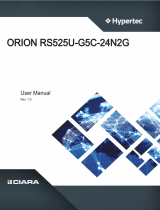
3�1 Motherboard Block Diagram
DMI GEN3@8GT/s
LGA3647-0 Socket
SPI Flash
W25Q64BVSSIG
CPU TDP 145W
Platform Environment Control Interface(PECI)
DMI3 x 4
S25FL256SAGMFI001
Flash
Debug port
USB#3
USB#2
ECC DDR4 (1866/2133/2400/2667)
CPU0
MUX
USB#0
USB#1
DIMM #A0
DIMM #B0
DIMM #C0
DIMM #D0
DIMM #E0
CPU0_VRD
VR13
XDP
Skylake-SP
(Cannonlake-SP)
CPU1
LGA3647-0 Socket
DIMM #G0
CPU TDP 145W
DIMM #I0 DIMM #K0
DIMM #L0
ECC DDR4 (1866/2133/2400/2667)
TDP 19W
Lewisburg-4
PCH
SATAPort #0~9
SATA#0
SATA#1
SATA#2
SATA#3
PCIe slot X8 (Support NTB)
PCIe slot X16
Port3(IOU2)
PCI-E GEN3 @8GT/s X8
Port2(IOU1)
PCI-E GEN3 @8GT/s X16
Port3(IOU2) Port1(IOU0)
LPC/eSPI
Platform Environment Control Interface(PECI)
@6Gb/s
PCIe5
PCIe4(NTB)
PCIe1(NTB)
PCIe2
P1 CH3/DIMM0/A0
P1 CH5/DIMM0/A8
P1 CH4/DIMM0/A4
P1 CH0/DIMM0/A0
P1 CH1/DIMM0/A4
P0 CH0/DIMM0/A
0
P0 CH1/DIMM0/A
4
P0 CH2/DIMM0/A
8
P0 CH3/DIMM0/A
0
P0 CH4/DIMM0/A
4
CPU0
CPU1
Placement
SATA#6
SATA#7
USB2.0 Port #0~3
@5Gb/s
USB3.0 Port #0~3
DIMM #F0DIMM #H0 DIMM #J0
CPU1_VRD
VR13
PCIe slot2
PCIe slot3
PCIe slot4
PCIe slot5
Port2(IOU1)
NGFF M.2 2242/2280
MUX x1
PCIE x4 or SATA x1
PCI-E GEN3 @8GT/s X4 & SATA @6Gb/s
SATAPort #10
@6Gb/s
SATA#8
SATA#9
P0 CH5/DIMM0/A
8
P1 CH2/DIMM0/A8
PCIe3
PCI Express x 4
PCI Express x 16
PCIe slot X16
PCI-E GEN3 @8GT/s X16
LSI
SAS3008
SASPort x4
@12Gb/s
SASPort x4
@12Gb/s
PCI Express x 16
S25FL256SAGMFI001
NVSRAM
CY14V101LA-BA25
Flash
UART0
Debug port
ICE0
Debug port
PCIe slot X8
PCI-E GEN3 @8GT/s X8
Port1(IOU0)
LSISAS3008
NGFF M.2 2242/2280
PCIE x 8
PCI-E GEN3@8GT/s
SFF-8643
SFF-8643
PCI Express x 4
Port1a(IOU0)
Port1c(IOU0)
Port1d(IOU0)
PCI Express x 8
Port3c(IOU2)
Port2a(IOU1)
Port2a(IOU1)
Skylake-SP
(Cannonlake-SP)
Port3a(IOU2)
SFF-8643
SFF-8643
SFF-8643
SFF-8643
PCI Express x 4
SATA#4
SPI
NUVOTON
NPCT650
SPI Flash
W25Q128V
TPM 2.0
(Internal Box Header )
Edge Connector
RJ45 x1
SPI
SPI2
USB(X2)
RMII
Aspeed AST2500
VGA CONN
VGA Pin Header
PCI Express x 1
COM1
(DB-9 CONN)
Pin Header
BMC Debug
Box Header
COM2
(1x3 pin)
JCOM4
(2x5 pin)
USB(X2)
ADM213
ADM213
COM5
USB2.0 Port #4~5
Box Header
(2x5 pin)
SFP x2
NCSI
ADM213
COM1
AST_USB Port #0~1 to PCH Port #4~5
EDY4016AABG-DR-F-D
DDR4 x16
COM4
LCM
Pin Header
(1x5 pin)
Secure boot key
PCI Express x 8
Port3c(IOU2)
PCI Express x 8
UPI
UPI @10.4GT/s
UPI1 UPI0
UPI0UPI1
UPI
UPI @10.4GT/s
SFF-8643
SFF-8643
PCIe slot X8 (Support NTB)
PCIe slot1
PCI Express x 8
Port3a(IOU2)
PCI-E GEN3 @8GT/s X8
SFF-8643
SFF-8643
SFF-8643
SFF-8643
SFF-8643
SFF-8643
SFF-8643
SFF-8643
Port1a(IOU0)
PCI Express x 4
Port1b(IOU0)
PCI Express x 4
Port1c(IOU0)
PCI Express x 4
Port1d(IOU0)
PCI Express x 4
10/100Mbps dedicate
management port
RTL8201EL
SFIx2
SFIx2
I2C4
LM95241CIMM
LM95241CIMM-1
LM95241CIMM-2
PCH
SFP
SFF-8612
SFF-8612(SFP)
SATA#5

24
Chapter 3 Motherboard Settings
3�2 Motherboard Layout
CPU 0
CPU 1CPU 1
CPU 0
1 2
4
4
5
6
10
11
1213
18
19
20
21
3
25
24
26
27
28
29
32
4045
a
45 c
47
51
55
56
57
58 59 60
62
63
64
65 66
67
5253
54
42 41
7
14
a
50
a
61
17
36
31
30
46
38
23
33
22
34
39
3437
35
48
49
b
8
9
b
9
a
b
45 b
a
8
a
15
12 Dimm Sockets
43
1 2 3 4
43
5 6
44

25
Chapter 3 Motherboard Settings
SB102-VG User's Manual
3�3 Motherboard Content List
Connectors Location Connectors Location
1 Power Supply JPWR1 34 Speaker JSPKR
2 Power Supply JPWR2 35 BIOS Recovery Mode J9
3 Power Supply JPWR3 36
ME Force Recovery
Mode
J3
4 Power Supply JPWR4 37
Flash Descriptor
Security override
J8
5 Power Supply JPWR5 38
No Reboot
(Watch Dog)
J26
6 SATA-DOM Power JDOM_PWR 39
NTB
(Non-Transparent
Bridge)
JNTB
7 Front Panel JFRNT_SSI 40 PCH GPIO JPCH_GPIO
8a
8b
Serial ATA SATA4
、
SATA5 41 NGFF JNGFF
9a
9b
MINISAS SATA0_3
、
SATA6_9 42
Internal
10GbE(Reserved)
J7
10 VGA JVGA_INT 43 PCIE3.0 CN1~CN6
11 COM1 JCOM1 44 SAS3.0 CN7
、
CN8
12 COM4 JCOM4
45a
45b
45c
External Thermal
Sensor
J2
、
J13
、
J24
13 LCM JLCM(COM3) 46
BMC Debug Port
Select
J27
14 Front USB JUSB_INT 47 VROC Key JRAID_KEY
15 XDP CONN JCPU_XDP 48 SATA4 PIN-7 Power J10
16 DIMM Sockets
JEDEC Specified
DDR4 Connector
49 SATA5 PIN-7 Power J11
17 Debug Port JLPC_DP 50 PCIE Hot-Plug SMB JPCIE_HP
18 ESPI Port JESPI 51 VRM SMB JSMB_VR
19 BMC Debug Port JBMC_DP 52
PCIE Hot-Plug Front
Panel
J4(CN5&CN6)
20 BMC GPIO JBMC_GPIO 53
PCIE Hot-Plug Front
Panel
J5(CN3&CN4)
21 SGPIO JSGPIO 54
PCIE Hot-Plug Front
Panel
J6(CN1&CN2)
22 SSGPIO JSSGPIO 55 CPU1 FAN CONN J1
23 Clear CMOS JCMOS 56 CPU0 FAN CONN J22
24 BMC I2C10 JBMC_I2C10 57 PCH FAN CONN J21
25 BMC IPMI JBMC_I2C1 58 FAN1A CONN J18
26 Battery Socket JBAT 59 FAN1B CONN J23
27 Intruder JINTRUDER 60 FAN2A CONN J17
28 PMBUS JPMBUS 61 FAN2B CONN J16
29 SPI ROM Socket JSPI_BIOS 62 FAN3A CONN J15
30 BMC Reset JBMC_RST 63 FAN3B CONN J14
31 BMC Disable JBMC_DIS 64 SAS IOC UART J20
32 BMC Buzzer JBUZZER 65
SAS IOC ACTIVITY
LED
J19
33 System PG Lock JPG_LOCK 66 SAS IOC ERROR LED J25
67 SAS IOC ICE J12

26
Chapter 3 Motherboard Settings
3�4 Internal Connectors/Jumpers
Connectors Location
12 COM4 JCOM4
13 LCM JLCM(COM3)
19 BMC Debug Port JBMC_DP
20 BMC GPIO JBMC_GPIO
21 SGPIO JSGPIO
24 BMC I2C10 JBMC_I2C10
25 BMC IPMI JBMC_I2C1
27 Intruder JINTRUDER
30 BMC Reset JBMC_RST
32 BMC Buzzer JBUZZER
45a
45b
45c
External Thermal
Sensor
J2
、
J13
、
J24
47 VROC Key JRAID_KEY
121319
20
21
25
24
27
32
45
a
47
30
1
2

27
Chapter 3 Motherboard Settings
SB102-VG User's Manual
DSR
RTS
CTS
RI
NC
DCD
RXD
TXD
DTR
GND
JCOM4
12
SW_PWR_BTN#
SW_RST_BTN#
TXDC
RXDC
GND
JLCM
13
BMC_UART_TXD5
BMC_UART_RXD5
GND
JBMC_DP
19
BMC_GPY0
BMC_GPY1
EXTRST#
I2C9SCL
I2C9SDA
GND
JBMC_GPIO
20
PCH_SCLOCK
PCH_SLOAD
PCH_SDATAOUT0
+3.3V
PCH_SDATAOUT1
GND
JSGPIO
21
GND
I2C10SDA
I2C10SCL
JBMC_I2C10
24
I2C1SDA
GND
I2C1SCL
NC
JBMC_I2C1
25
27
BMC_BUZZER
+5V
JBUZZER
32
GND
+3.3V_DUAL
GND
PCH_GPP_C10
JRAID_KEY
47
HM_TD5-
HM_TD5+
J2
45 a

28
Chapter 3 Motherboard Settings
Connectors Location
6 SATA-DOM Power JDOM_PWR
17 Debug Port JLPC_DP
18 ESPI Port JESPI
22 SSGPIO JSSGPIO
40 PCH GPIO JPCH_GPIO
51 VRM SMB JSMB_VR
57 PCH FAN CONN J21
67 SAS IOC ICE J12
6
18
40
51
57
67
17
22

29
Chapter 3 Motherboard Settings
SB102-VG User's Manual
GND
+5V
JDOM_PWR
6
PCH_LPC_LAD0
+3.3V
PCH_LPC_LAD3
RST_PLTRST_N
PCH_LFRAME_N
CLK_24M_DP80
GND
PCH_LPC_LAD1
PCH_LPC_LAD2
AST_SERIRQ
PCH_LDRQ0_N
GND
11
JLPC_DP
17
PCH_ESPI_ALENT1_N
PCH_ESPI_RST_N
SMB_HOST_3V3_CLK
SMB_HOST_3V3_DAT
PGPPA_PCH
GND
PCH_PME_N
PCH_LPC_CLKRUN_N
PCH_SMI_N
+5V_AUX
10
JESPI
18
GND
PCH_SSDATAOUT1
+3.3V
PCH_SSDATAOUT0
PCH_SSLOAD
PCH_SSCLOCK
JSSGPIO
22
PCH_GPP_C16
PCH_GPP_C17
GND
JPCH_GPIO
40
SMB_VR_CLK
GND
SMB_VR_DAT
JSMB_VR
51
GND
+12V
TACH
PWM
J21
57
ICE0_TMS
ICE0_TDO
ICE0_TDI
N.C.
SYS_HALT_L0
ICE0_TRST_L
ICE0_TCK
SAS3008_1V8
GND
N.C.
J12
67

30
Chapter 3 Motherboard Settings
Connectors Location
7 Front Panel JFRNT_SSI
14 Front USB JUSB_INT
41 NGFF JNGFF
42
Internal
10GbE(Reserved)
J7
45a
45b
45c
External Thermal
Sensor
J2
、
J13
、
J24
50 PCIE Hot-Plug SMB JPCIE_HP
52
PCIE Hot-Plug Front
Panel
J4(CN5&CN6)
53
PCIE Hot-Plug Front
Panel
J5(CN3&CN4)
54
PCIE Hot-Plug Front
Panel
J6(CN1&CN2)
5253
54
42 41
7
14
a
50
a
b
45 b

31
Chapter 3 Motherboard Settings
SB102-VG User's Manual
+3.3V_DUAL
+5V_AUX
UIDLED_OUT#
SYS_HEALTH#2
SYS_HEALTH#1
LAN1_LINK_UP
LAN1_TRAFFIC
I2C8SDA
I2C8SCL
INTRUDER#
LAN2_LINK_UP
LAN2_TRAFFIC
PWR_LED
KEY (no pin)
PWR_LED#
+3.3V
HD_LED#
SW_PWR_BTN#
GND
SW_RST_BTN#
GND
UID_SW_IN#
+3.3V_DUAL
FP_NMI_BTN
7
JFRNT_SS1
+5V_USB23
PCH_FP_USB3_RX_N2
PCH_FP_USB3_RX_P2
GND
PCH_FP_USB3_TX_N2
PCH_FP_USB3_TX_P2
GND
PCH_FP_USB2_N2
PCH_FP_USB2_P2
PCH_USB_OC#23
KEY (no pin)
+5V_USB23
PCH_FP_USB3_RX_N3
PCH_FP_USB3_RX_P3
GND
PCH_FP_USB3_TX_N3
PCH_FP_USB3_TX_P3
GND
PCH_FP_USB2_N3
PCH_FP_USB2_P3
JUSB_INT
14
3V3
GND
SFI_L2_RX_DP
SFI_L2_RX_DN
GND
SFI_L3_RX_DP
SFI_L3_RX_DN
GND
LAN_TX_FAULT3
LAN_TX_DISABLE3
GND
LAN_SDA3
LAN_SCL3
GND
LAN_MOD_ABS3
RS0/RS1_SENSE3
GND
LAN_RX_LOS3
RS0/RS1_DRIVE3
GND
RSVD_1
RSVD_2
GND
SFI_L2_TX_DP
SFI_L2_TX_DN
GND
SFI_L3_TX_DP
SFI_L3_TX_DN
GND
LAN_TX_FAULT2
LAN_TX_DISABLE2
GND
LAN_SDA2
LAN_SCL2
GND
LAN_MOD_ABS2
RS0/RS1_SENSE2
GND
LAN_RX_LOS2
RS0/RS1_DRIVE2
GND
3V3
J7
42
HM_TD6-
HM_TD6+
45 b
J13
CPU0_HP_I2C_CLK
CPU0_HP_I2C_DA
+3.3V
CPU1_HP_I2C_CLK
CPU1_HP_I2C_DAT
GND
JPCIE_HP
50

32
Chapter 3 Motherboard Settings
JNGFF
GND
GND
GND
GND
GND
GND
GND
GND
GND
GND
GND
GND
GND
GND
NC
NGFF_PEDET
PERn1
PETn1
PERp1
PETp1
PERn0_SATA-B+
PERp0_SATA-B-
PETn0_SATA-A-
PETp0_SATA-A+
REFCLK_N
REFCLK_P
PERn3
PETn3
PETp3
PERn2
PERp2
PETn2
PETp2
PERp3
VCC3_3_2
VCC3_3_4
DAS_DSS#(O)(OD)
VCC3_3_16
NC
NC
NC
NC
NC
PERST#(I)(0_3V3)
Reserved_MFG Data
Reserved_MFG Clock
NC
NC
NC
DEVSLP(I)(0_3V3)
NC
NC
NC
CLKREQ#(IO)(0_3V3)
PEWake#(IO)(0_3V3)
SUSCLK(32kHz)(I)(0_3V3)
VCC3_3_74
VCC3_3_70
VCC3_3_72
NC
VCC3_3_12
VCC3_3_14
VCC3_3_18
NC
NC
NC
NC
57
58
1
2
75
74
67
68
41

33
Chapter 3 Motherboard Settings
SB102-VG User's Manual
+3.3V
PRSNT-2
PWR FAULT-2
PWR ENABLE-2
ATTEN BUTTON-
2
MRL/EMIS-2
EMIL-2
ATTEN LED-2
PWR LED-2
GND
+3.3V
PRSNT-1
PWR FAULT-1
PWR ENABLE-1
ATTEN BUTTON-1
MRL/EMIS-1
EMIL-1
ATTEN LED-1
PWR LED-1
GND
J4
52
+3.3V
PRSNT-4
PWR FAULT-4
PWR ENABLE-4
ATTEN BUTTON-4
MRL/EMIS-4
EMIL-4
ATTEN LED-4
PWR LED-4
GND
+3.3V
PRSNT-3
PWR FAULT-3
PWR ENABLE-3
ATTEN BUTTON-3
MRL/EMIS-3
EMIL-3
ATTEN LED-3
PWR LED-3
GND
J5
53
+3.3V
PRSNT-6
PWR FAULT-6
PWR ENABLE-6
ATTEN BUTTON-6
MRL/EMIS-6
EMIL-6
ATTEN LED-6
PWR LED-6
GND
+3.3V
PRSNT-5
PWR FAULT-5
PWR ENABLE-5
ATTEN BUTTON-5
MRL/EMIS-5
EMIL-5
ATTEN LED-5
PWR LED-5
GND
J6
54

34
Chapter 3 Motherboard Settings
Connectors Location
3 Power Supply JPWR3
4 Power Supply JPWR4
28 PMBUS JPMBUS
56 CPU0 FAN CONN J22
58 FAN1A CONN J18
59 FAN1B CONN J23
60 FAN2A CONN J17
61 FAN2B CONN J16
62 FAN3A CONN J15
63 FAN3B CONN J14
64 SAS IOC UART J20
65
SAS IOC ACTIVITY
LED
J19
66 SAS IOC ERROR LED J25
4
3
28
56
58 59 60
62
63
64
65 66
61

35
Chapter 3 Motherboard Settings
SB102-VG User's Manual
SAS3008_1V8
UART0_RX
GND
UART0_TX
J20
+12V
+12V
+12V
+12V
GND
GND
GND
GND
JPWR4
GND
+12V
TAC
H
PWM
J22
+3.3V
SAS_PHY4 Error LED
SAS_PHY5 Error LED
SAS_PHY6 Error LED
SAS_PHY7 Error LED
GND
SAS_PHY0 Error LED
SAS_PHY1 Error LED
SAS_PHY2 Error LED
SAS_PHY3 Error LED
J19
+3.3V
SAS_PHY4 Active LED
SAS_PHY5 Active LED
SAS_PHY6 Active LED
SAS_PHY7 Active LED
GND
SAS_PHY0 Active LED
SAS_PHY1 Active LED
SAS_PHY2 Active LED
SAS_PHY3 Active LED
J25
J23
GND
+12V
TACH
PWM
PRSNT_N
FAULT
J23
GND
+12V
TACH
PWM
PRSNT_N
FAULT
J17
GND
+12V
TACH
PWM
PRSNT_N
FAULT
J16
GND
+12V
TACH
PWM
PRSNT_N
FAULT
J15
GND
+12V
TACH
PWM
PRSNT_N
FAULT
J14
59 60
61
62
64
66
4
63
56
65
+12V
+12V
+12V
+12V
GND
GND
GND
GND
JPWR3
3
+3.3V
GND
PMBUS_ALERT_N
SMB_PMBUS_DATA
SMB_PMBUS_CLK
JPMBUS
28
GND
+12V
TACH
PWM
PRSNT_N
FAULT
J18
J18
58

36
Chapter 3 Motherboard Settings
Connectors Location
1 Power Supply JPWR1
2 Power Supply JPWR2
5 Power Supply JPWR5
10 VGA JVGA_INT
11 COM1 JCOM1
45a
45b
45c
External Thermal
Sensor
J2
、
J13
、
J24
55 CPU1 FAN CONN J1
CPU 1CPU 1
12
5
10
11
45 c
55
HM_TD3+
HM_TD3-
J24
GND
+12V
TACH
PWM
J1
DSR
RTS
CTS
RI
NC
DCD
RXD
TXD
DTR
GND
JCOM1
11
55
45 c
+12V
+12V
+12V
+12V
GND
GND
GND
GND
JPWR1
GND
+5V
+5V
+5V
NC
GND
GND
GND
PS_ON#
GND
-12V
+3.3V
+3.3V
+12V
+12V
+5V_AUX
POWER OK
GND
+5V
GND
+5V
GND
+3.3V
+3.3V
JPWR2
1 2
GND
+12V
GND
+12V
JPWR5
5
DVO_5V
GND
DDC_DATAO
AVSYNCO
AHSYNCO
DDC_CLKO
GND
DACROA
GND
DACGOA
GND
DACBOA
JVGA_INT
10
/