Page is loading ...

Installation and
Maintenance
Instructions
B-2740 SERIES
SINGLE LEVER FAUCETS
(with or without Sidespray)
Limited One Year Warranty
T&S warrants to the original purchaser
(other than for purposes of resale) that
such product is free from defects in
material and workmanship for a period
of one (1) year from the date of purchase.
During this one-year warranty period, if the
product is found to be defective, T&S shall,
at its options, repair and/or replace it. To
obtain warranty service, products must be
returned to...
T&S Brass and Bronze Works, Inc.
Attn: Warranty Repair Department
2 Saddleback Cove
Travelers Rest, SC 29690
Shipping, freight, insurance, and other
transportation charges of the product
to T&S and the return of repaired or
replaced product to the purchaser are
the responsibility of the purchaser. Repair
and/or replacement shall be made within
a reasonable time after receipt by T&S of
the returned product. This warranty does
not cover Items which have received
secondary fi nishing or have been altered
or modifi ed after purchase, or for defects
caused by physical abuse to or misuse of
the product, or shipment of the products.
Any express warranty not provided
herein, and any remedy for Breach of
Contract which might arise, is hereby
excluded and disclaimed. Any implied
warranties of merchantability or fi tness
for a particular purpose are limited to one
year in duration. Under no circumstances
shall T&S be liable for loss of use or any
special consequential costs, expenses or
damages.
Some states do not allow limitations
on how long and implied warranty lasts
or the exclusion or limitation of incidental
or consequential damages, so the above
limitations or exclusions may not apply to
you. Specifi c rights under this warranty
and other rights vary from state to state.
P/N: 098-016721-45 Rev. 0
Date: 02-19-08
Drawn: TEH
Checked: ARH 04-08-08
Approved: JHB 04-09-08

2
Exploded View
1
2
3
6
4
5
9
7A
8
10
11
7B
Gooseneck Assembly for
B-2741, B-2742 & B-2746
1F
1C
1D
1E
1B
1G
1A
B-2740 Side Mount
Mixer Assembly
* Some items are listed for instructional purposes
and may not be sold as separate parts.

* Some items are listed for instructional purposes
and may not be sold as separate parts.
3
Exploded View
8
11
13
7A
14
12
10
9
15
16
17
18
12
7B
Gooseneck Assembly for
B-2743, B-2744 & B-2749

Part Number Guide
4
B-2740 Side Mount Mixer Assembly
1 Body Base w/ Supply Lines & Outlet *
A Handle Kit 013113-45
B Cartridge 013080-45
C Index, Temperature 014173-45
D Trim Ring 016661-45
E Locking Nut 016663-45
F Inlet & Outlet Hose 013537-45
G Set Screw 016675-45
2 Deck Mounting Ring *
3 Deck Mounting Ring O-Ring *
4 Threaded Locking Rod *
5 Brass Lock Nut *
6 Locking C-Ring *
Gooseneck Assembly for: B-2741 B-2742 B-2746
7A Gooseneck BL-5570-02 133X B-2403
7B Aerator B-0199-07 B-0199-06 B-0199-01
8 Center Body Assembly B-0430 B-0431 B-0431
9 Center Body Shank * * *
10 Washer 000999-45 000999-45 000999-45
11 Nut 002954-45 002954-45 002954-45
Gooseneck Assembly for: B-2743 B-2744 B-2749
7A Gooseneck 000398-40
7B Aerator B-0199-06 B-0199-06
8 Center Body Assembly B-0431 B-0431 009435-40
9 Center Body Shank * * *
10 Washer 000999-45 000999-45 000999-45
11 Nut 002954-45 002954-45 002954-45
12 Set Screw 001486-45 001486-45
13 Valve Body *
14 Diverter Valve 002338-45 002338-45 002338-45
15 Guide Assembly 001496-45 001496-45 B-KF
16 Shank * * N/A
17 Combo Nut Washer * * N/A
18 Side Spray Assembly B-0101
Side Spray, 4’ 001495-45 001495-45
Side Spray, 7’ 013659-45 013659-45

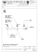
Note: An adjustable wrench may be used instead of an open end wrench.
Installation of Side Mount Mixer (No.1) B-2740
1. Shut off water supply and drain lines. Drill a hole approximately 1-1/2” diameter
in countertop where installing no.1 (side mount body).
2. Take no.1 (side mount body) and no.2 (mounting ring) (see note) and place
no.2 (mounting ring) on top of counter over 1-1/2” diameter hole. Place hoses
of no.1 (side mount body) through hole and place no.1 (side mount body) into
no.2 (mounting ring). Note: No.3 (mounting o-ring) should be installed in no.2
(mounting ring).
3. From below counter, thread no.4 (threaded locking rod) into hole in bottom of
no.1 (side mount body).
4. Install no.6 (locking c-ring) and then no.5 (brass lock nut) onto no.4 (threaded
locking ring). Hex of no.5 (brass lock nut) should be at bottom for ease of
installation. Tighten no.5 (brass lock nut) with a 3/8” wrench until no.6 (locking c-
ring) is snug against underside of countertop. Note that no.5 (brass lock nut) and
no.6 (locking c-ring) can adjust to counter thickness up to two inches.
5. Connect fl exible supply lines (3/8” female compressions) to water supply. Note
stickers on supply lines, with red sticker indicating hot and blue sticker cold.
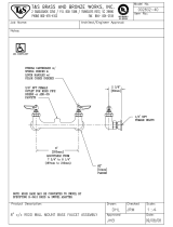
Installation of Gooseneck Assembly, included in B-2741, B-2742 &
B-2746 Assemblies:
1. With water supply and drain lines shut off from step 1 above, drill a 7/8”
diameter hole in countertop where no.8 (center body assembly) is to be installed.
The hole should be no more than 6” maximum from center of hole for side mount
mixer in step 1. For rigid gooseneck assembly, no.8 (center body assembly) and
no.7 (gooseneck) are one assembly. For the swivel gooseneck assembly, no.8
(center body assembly) and no.7 (gooseneck) are separate assemblies.
2. Remove no.11 (nut) and no.10 (washer) before placing no.9 (center body shank)
of no.8 (center body assembly) through hole above countertop. After installing
no.8 (center body assembly) in 7/8” diameter hole, put no.10 (washer) and no.11
(nut) back on no.9 (center body shank) below countertop and tighten with 1”
wrench until tight with countertop.
3. Connect outlet hose from side mount mixer to inlet of no.9 (center body
shank). Tighten sung with 15/16” wrench.
4. FOR SWIVEL ONLY: Install no.7 (gooseneck) by screwing nut of no.7 (gooseneck)
onto top of no.9 (center body shank). Install grease from packet on swivel o-ring
prior to screwing on no.9 (center body shank). Tighten with 1-1/8” wrench.
5. Open water supply and check for leaks. Lift handle on side mount mixer and
check for leaks.
5
General Instructions

6
General Instructions
Installation of Gooseneck w/ Side Spray Assembly, Included in
B-2743, B-2744 & B-2749 Assemblies:
1. With water supply and drain lines shut off from step 1 in Installation of
Gooseneck Assembly, drill a 7/8” diameter hole in countertop where no.8 (center
body assembly) is to be installed. The hole should be no more than 6” maximum
from center of hole for side mount mixer. For rigid gooseneck assembly no.8
(center body assembly) and no.7 (gooseneck) are one assembly. For the swivel
gooseneck assembly no.8 (center body assembly) and no.7 (gooseneck) are
separate assemblies.
2. Remove no.12 (set screw) from no.7 (gooseneck) with fl at head screw driver.
Carefully twist and pull no.7 (gooseneck) from no.8 (center body assembly). No.14
(diverter valve) should be visible in top of no.9 (center body shank) of no.8 (center
body assembly). With fl at head screw driver, turn screw in top of no.14 (diverter
valve) counter clockwise to loosen valve. Remove no.14 (diverter valve) from top
of no.8 (center body assembly) and set aside. With 3/4” wrench use fl ats on no.9
(shank) to remove no.8 (center body assembly) from no.13 (valve body). Remove
no.11 (nut) and no.10 (washer) before placing no.9 (center body shank) of no.8
(center body assembly) through hole above countertop. After installing no.8
(center body assembly) in 7/8” diameter hole, put no.10 (washer) and no.11 (nut)
back on no.9 (center body shank) below countertop and tighten with 1” wrench
until tight with countertop.
3. Reinstall no.13 (valve body) below countertop on bottom of no.9 (center body
shank).
4. With screwdriver reinstall no.14 (diverter valve) above countertop in no.8
(center body assembly).
5. Connect outlet hose from side mount mixer to inlet of no.13 (valve body).
Tighten snug with 15/16” wrench.
6. Install no.15 (guide assembly) for no.18 (side spray assembly) by removing
no.17 (combo nut washer) from no.15 (guide assembly). Place no.16 (shank) with
bonnet through hole in countertop for no.18 (side spray assembly). Thread lock
nut & washer on bottom of no.16 (shank) of no.15 (guide assembly) beneath
countertop. Thread tightly.
7. Place no.18 (side spray assembly) hose (1/8” NPT) fi tting through no.15 (guide
assembly) on top of countertop until spray handle rests in no.15 (guide assembly).
Below countertop install no.18 (side spray assembly) hose fi tting into bottom of
no.13 (valve body) with 3/8” wrench.
8. FOR SWIVEL ONLY: Install no.7 (gooseneck) by installing gooseneck onto top of
shank of no.8 (center body assembly) sticking out top of counter. Install grease
from packet on swivel o-rings prior to installing on no.9 (center body shank).
Install set screws in gooseneck base.
9. Open water supply and check for leaks. Lift handle on side mount mixer and
check for leaks. Use side spray and check for leaks.

T&S BRASS AND BRONZE WORKS, INC.
A fi rm commitment to application-engineered plumbing products
2 Saddleback Cove, P.O. Box 1088 T & S Brass-Europe
Travelers Rest, SC 29690 ‘De Veenhoeve’
Phone: (864) 834-4102 Oude Nieuwveenseweg 84
Fax: (864) 834-3518 2441 CW Nieuwveen
E-mail: [email protected]om The Netherlands
B-2710
Single Lever Faucet
B-2711
Single Lever Faucet
with Pop-Up Drain Assembly
B-2730
Single Lever Mixing
Faucet with Sidespray
B-2731
Single Lever Mixing
Faucet less Sidespray
RELATED T&S BRASS PRODUCT LINE
/