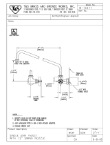
Nozzle Installation
Note: Nozzle should be installed rst. See diagram below.
Note: Nozzle should be installed rst. See diagram below.
1.
Shut o water supply and drain lines. Insert no.
Shut o water supply and drain lines. Insert no.
16
into no.
1 and rotate to front of sink. For a
and rotate to front of sink. For a
rigid nozzle, install no.
rigid nozzle, install no.
13
into no.
outlet.
2.
Tighten no.
19
rmly with a wrench.
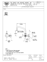
Faucet Installation
3.
Drill (2) two holes into sink
Drill (2) two holes into sink
or countertop where you are
or countertop where you are
installing no.
.
Note: Inlet spacing: 3-1/2", 4" or 8"
Note: Inlet spacing: 3-1/2", 4" or 8"
center to center.
4.
Apply Plumber's Putty to the
Apply Plumber's Putty to the
bottom face of no.
. Position
no.
1 into the drilledcountertop.
into the drilledcountertop.
5.
Install no.
and no.
on each
no.
1 shank and tighten. Install
shank and tighten. Install
no.
4 if they are tobeused.
if they are tobeused.
6.
Connect water supply to no.
Connect water supply to no.
shanks or no.
(if applicable) and
check for leaks.
NOTE: See repair kit
011643-45 for replacement of no.
011643-45 for replacement of no.
22
and no.
23
.
NOTA: Vea el kit de reparación 011643-45
NOTA: Vea el kit de reparación 011643-45
paralas refacciones delaspiezas n.º
paralas refacciones delaspiezas n.º
22
y
23
.
REMARQUE : Voir le kit deréparation 011643-45
REMARQUE : Voir le kit deréparation 011643-45
pour le remplacement desNo
pour le remplacement desNo
22
et
23
.
HINWEIS: Reparatursatz 011643-45 zum Ersatz
HINWEIS: Reparatursatz 011643-45 zum Ersatz
vonNr.
22
und Nr.
23
注意:
22
23
号的配件包型号为
. 011643-45
23
21
22
16
19
1, 5
13
countertop
Cubierta superior
Comptoir
Arbeits äche
台面
(optional
(opcional)
(en option)
(optional)
(选配件)
Instalación de la boquilla
Instalación de la boquilla
Nota: Se debe instalar la boquilla en primer lugar. Véase el siguiente diagrama.
Nota: Se debe instalar la boquilla en primer lugar. Véase el siguiente diagrama.
1.
Corte el suministro de agua y drene las líneas. Inserte la pieza n.º
Corte el suministro de agua y drene las líneas. Inserte la pieza n.º
16
en la n.º
y gire hacia el
frente del fregadero. En el caso de una boquilla rígida, instale la pieza n.º
frente del fregadero. En el caso de una boquilla rígida, instale la pieza n.º
13
en la salida n.º
2.
Apriete rmemente la pieza n.º
Apriete rmemente la pieza n.º
19
, con una llave.
Instalación del grifo
3.
Perfore dos (2) ori cios en el fregadero o en la cubierta superior, en donde está instalando la
Perfore dos (2) ori cios en el fregadero o en la cubierta superior, en donde está instalando la
pieza n.º
.
Nota: Espaciado en la entrada: Distancia entre centros de 8.89, 10.16 o 20.32 cm (3-1/2", 4" o 8").
Nota: Espaciado en la entrada: Distancia entre centros de 8.89, 10.16 o 20.32 cm (3-1/2", 4" o 8").
4.
Coloque masilla de plomería en la super cie inferior de la pieza n.º
Coloque masilla de plomería en la super cie inferior de la pieza n.º
. Coloque la pieza n.º
en
la cubierta superior perforada.
la cubierta superior perforada.
5.
Instale las piezas n.º
y n.º
en cada vástago n.º
1 y apriete. Instale las piezas n.º
y apriete. Instale las piezas n.º
sivan a
usarse.
6.
Conecte el suministro de agua a los vástagos de la pieza n.º
Conecte el suministro de agua a los vástagos de la pieza n.º
o a la pieza n.º
(siaplica) y
compruebe que no haya fugas.
compruebe que no haya fugas.
ES
FR
DE
CN
EN
ES
FR
DE
CN
EN
Installation de la lance
Remarque : La lance doit être installée en premier. Voir le schéma ci-dessous.
Remarque : La lance doit être installée en premier. Voir le schéma ci-dessous.
1.
Coupez l'alimentation en eau et les conduites d'évacuation. Insérez le No
Coupez l'alimentation en eau et les conduites d'évacuation. Insérez le No
16
dansleNo
et
faites pivoter vers l'avant de l'évier. Pour une lance rigide, installezle
faites pivoter vers l'avant de l'évier. Pour une lance rigide, installezle
13
dans la sortie No
2.
Serrez bien le No
19
avec une clé.
Einbau der Düse
Hinweis: Düse muss zuerst montiert werden. Siehe Abbildung unten.
Hinweis: Düse muss zuerst montiert werden. Siehe Abbildung unten.
1.
Wasserzufuhr ausschalten und Rohre entleeren. Nr.
Wasserzufuhr ausschalten und Rohre entleeren. Nr.
16
in Nr.
1 einsetzen und zur Vorderseite
einsetzen und zur Vorderseite
des Beckens drehen. Bei starrer Düse Nr.
des Beckens drehen. Bei starrer Düse Nr.
13
in Nr.
Auslass einsetzen.
2.
Nr.
19
mit einem Schraubenschlüssel fest anziehen.
mit einem Schraubenschlüssel fest anziehen.
水嘴安装
注意:水嘴要最先安装。请参见下方图解。
1.关闭供水及排水管道,将16号插入1号内并旋转至水池前方。如果是固定水嘴,则应将13
号放入1号出水口内。
2.用扳手将19号拧紧。
Faucet Installation
3.
Forez (2) trous dans l'évier ou le comptoir à l'endroit où vous installez le No
Forez (2) trous dans l'évier ou le comptoir à l'endroit où vous installez le No
.
Remarque : Espacement entre les entrées : 3 1/2 po., 4 po. ou 8 po. entre les axes.
Remarque : Espacement entre les entrées : 3 1/2 po., 4 po. ou 8 po. entre les axes.
4.
Appliquez du mastic de plombier sur la face inférieure du No
Appliquez du mastic de plombier sur la face inférieure du No
. Mettez en place leNo
dans
le comptoir percé.
5.
Installez les No
et
3 sur chacune des douilles No
sur chacune des douilles No
1 et serrez. Installez les No
et serrez. Installez les No
s'ilsdoivent
être utilisés.
6.
Raccordez l'arrivée d'eau aux douilles No
Raccordez l'arrivée d'eau aux douilles No
ou No
4 (le cas échéant) et recherchez des fuites.
(le cas échéant) et recherchez des fuites.
Montage der Armatur
3.
Zwei (2) Bohrlöcher in die Spüle oder die Arbeitsplatte an der Stelle bohren, woNr.
Zwei (2) Bohrlöcher in die Spüle oder die Arbeitsplatte an der Stelle bohren, woNr.
einge-
baut wird.
Hinweis: Abstand des Einlass: 3-1/2", 4" oder 8" von Mitte zu Mitte.
Hinweis: Abstand des Einlass: 3-1/2", 4" oder 8" von Mitte zu Mitte.
4.
Den Kitt auf die Unterseite von Nr.
Den Kitt auf die Unterseite von Nr.
auftragen. Nr.
1 in die Bohrungen der Arbeitsplatte
in die Bohrungen der Arbeitsplatte
platzieren.
5.
Nr.
und Nr.
an jedem Schaft Nr.
1 montieren und festziehen. Nr.
montieren und festziehen. Nr.
einbauen, fallssie
verwendet werden sollen.
6.
Wasserzufuhr zum Schaft Nr.
Wasserzufuhr zum Schaft Nr.
oder Nr.
4 (falls zutre end) anschließen und aufDichtheit
(falls zutre end) anschließen und aufDichtheit
überprüfen.
龙头安装
3.在需安装龙头的水槽或者工作台面上钻两(2)个孔。
注意:两孔间距据具体安装的型号而定,可为3-1/2"(89mm),4"(102mm)或者
8”(203mm)。
4.在5号的底面涂上油灰,将1号安置到钻好孔的工作台面上。
5.把2号和3号安装到相应的1号接头上并拧紧。根据需求选装4号配件。
6.在1号接头处或者4号(如果有使用)处连接供水,并检查是否漏水。
4 5