Page is loading ...

Orbit Industries, Inc. 2100 S. Figueroa St. Los Angeles, CA 90007 Tel: (213) 745-8884 Fax: (213) 745-2015 1-800-90-ORBIT
WARRANTY OWNER: Orbit Industries, Inc., warrants to the original consumer purchaser that it’s products will be free from
defects in materials or workmanship for a period of one year from the date of original consumer purchase.
THERE ARE NO OTHER WARRANTIES, EXPRESS OR IMPLIED, INCLUDING, BUT NOT LIMITED TO, IMPLIED
WARRANTIES OF MERCHANTABILITY OR FITNESS FOR A PARTICULAR PURPOSE.
During this one year period, Orbit, will at its option, repair or replace , without charge, any products or part which is found to be
defective under normal use and service. THIS WARRANTY DOES NOT EXTEND TO FLUORESCENT LAMP STARTERS OR
TUBES, FILTERS, DUCT, ROOF CAPS, and OTHER ACCESSORIES FOR DUCTING.
This warranty does not cover (a) normal maintenance and service or (b) any products or parts which have been subject to
misuse, negligence, accident, improper maintenance of repair (other than by Orbit), faulty installation or installation contrary to
recommended installation instructions. The duration of any implied warranty is limited to the one year period as specified for the
express warranty. Orbit OBLIGATION TO REPAIR OR REPLACE, AT Orbit OPTION, LIABLE FOR INCIDENTAL,
CONSEQUENTIAL OR SPECIAL DAMAGES ARISING OUT OF OR IN CONNECTION WITH PRODUCT USE OR
PERFORMANCE. Some states do not allow the exclusion or limitation of incidental or consequential damages, so the above
limitation or exclusive may not apply to you. This warranty gives you specific legal rights, and you may have other rights, which
vary from state to state. This warranty supercedes all prior warranties.
WARRANTY SERVICE: To qualify for warranty service, you must (a) notify Orbit at the address stated below, (b) give the
model number and part identification and (c) describe the nature of any defect in the product or part. At the time of requesting
warranty service, you must present evidence of the original purchase date.
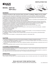
WARNING - TO REDUCE THE RISK OF FIRE, ELECTRIC SHOCK, OR INJURY TO
PERSON, OBSERVE THE FOLLOWING:
a) Use this unit only in the manner intended by the manufacturer. If you have questions, contact the manufacturer.
b) Before servicing or cleaning unit, switch power off at service panel and lock the service disconnecting means
to prevent power from being switched on accidentally. When the service disconnecting means cannot be
locked, securely fasten a prominent warning device, such as a tag, to the service panel.
"CAUTION - For General Ventilating Use Only. Do Not Use To Exhaust Hazardous Or Explosive Materials And Vapors."
" Do Not Mount In A Ceiling Thermally Insulated To A Value Greater Than R40"
WARNING - TO REDUCE THE RISK OF FIRE, ELECTRIC SHOCK, OR INJURY TO
PERSON, OBSERVE THE FOLLOWING:
a) Installation work and electrical wiring must be done by qualified person(s) in accordance with all applicable
codes and standards, including fire-rated construction.
b) When cutting or drilling into wall or ceiling, do not damage electrical wiring and other hidden utilities.
c) Ducted fans must always be vented to the outdoors.
d) If this unit is to be installed over a tub or shower, it must be marked as appropriate for the application and be
connected to a GFCI (Ground Fault Circuit Interrupter) - protected branch circuit.
WARNING:
a) "Do not install fan above or inside a 45-degree
angle projected outwards from the cooking equip-
ment element closest to the fan. See instruction
sheet for clarification;" or
b) "Not for use in cooking area - see installation
instructions;"
ROOF CAP*
(with built-in
damper)
ROUND
DUCT*
WALL CAP*
(with built-in
* Purchase
damper)
separately
POWER
CABLE*
INSULATION*
(Place around and
over Fan Housing.)
Seal gaps
around
Housing.
FAN
HOUSING
ROUND
ELBOW(S) *
Seal duct
joints with
tape.
Keep duct
runs short
Recommended to put insulation around and the fan housing to
minimize the building heat loss. Seal all the gaps around the
housing with caulk or other similar material to inhibit air leakage
to the exterior of the thermal envelope of the building. Rigid sheet
metal duct and the shortest path to the outside will minimize
static pressure losses and promote adequate flow.
Deluxe
ODU814M
READ AND SAVE THESE INSTRUCTIONS
“WARNING - To Reduce The Risk Of Electric Shock,
Do Not Use This Fan With Any Solid-State Speed Control Device.”

4” & 6” Termination (duct)
Rough Opening:
11-1/4” L X 10-1/2” W
Housing Dimension:
11-1/4” L X 10-1/2” W X 7-5/8” H
Carefully position fan
for shortest duct run and
fewest elbows to achieve
maximum performance
1. Remove grille from housing before installation.
2. Insert pair of sliding brackets in each bracket mount.
3. Locate housing between ceiling joists and truss so bottom
flange will fit flush to the ceiling joist.
4. Loosely screw to joist through the mounting bracket
KEYHOLE slots (screws not provided).
5. Optional side mount to ceiling joist and use one side of the
bracket for more stable support.
1. For new fan installation position the housing in the
attic next to the ceiling joist or truss.
2. Trace housing bottom edge on ceiling material for cutout.
3. Confirm the opening, then cut hole 11-1/4” X 10-1/2” of the
housing inside edge.
4. Place housing inside opening (attic) of the ceiling.
5. To attach follow steps 3, 4, 5 for New Construction.
Deluxe
ODU814M

-
+
-
+
1 2 3
1
Dip Switch
Power box
Low Airflow
Knob
Timer
Delay Knob
80 90 110 120 90 110 120 140
1
6"
Switch
position
Duct
diameter
(inches)
Airflow
(CFM)
6"
6"
6"4"4"4"4"
80 90 110 120 90 110 120 140
1 2 31 2 31 2 31 2
31 2 31 2 3
1 2 31 2 3
6"
Switch
position
Duct
diameter
(inches)
Air deliver
(CFM)
6"
6"
6"4"4"4"4"
Other airflow reference performance based on HVI Procedures
915, 916, and 920.
Factory setting: 110CFM ( )
HVI Certified performance based on HVI Procedures 915, 916,
and 920.
with 6" duct
2 3
2 3
1 2 3
1 2 3
1 2 3 1 2 3 1 2 3 1 2 3 1 2 3
Dip Switch Position
S T
OPERATION:
The control box, located inside the fan housing, has three separate adjustments:
(1) The low airflow knob (S) adjusts the lower airflow from 30CFM up to
the air flow rate of the high fan speed determined by the dip switch setting.
(2) The time delay knob (T) is adjustable from 3 to 30 minutes and will switch the fan
to the low speed setting after motion is no longer detected in the room for the period
of time.
(3) The dip switch will adjust the upper fan speed setting from 80 to 120 CFM
using a 4" duct or 90 to 140 CFM using a 6" duct. Both 4" & 6" duct adaptors are
included.
SERVICE PARTS
PART PART NAME Qty.
1
2
3
4
5
6
7
8
9
10
11
a
b
c
d
e
Housing
Damper / Duct Connector
Wiring plate
Screw
Blower Wheel
Wire Panel / Harness Assembly
Motor
1
2
1
1
1
1
1
1
1
4
1
12
Sensor (includes sensor system and LED light)
1
4
4
1
4
1
Isolator
Motor Plate
Washer
Nut, Hex Lock
Grille Assembly (includes part 2 & 12)
Grille Spring
Hanger Bar Kit
Screw
Power Box
* Blower Assembly includes part 6, 5, d, 4, c, b, a.
Replacement installation:
Remove the screw (part c), then take out the motor plate (part 4) from the
housing (part 9) by pushing down the rib in the plate while pulling out on
the side of the housing. Replace the broken parts.
WARNING: Before replacing, be sure to turn OFF power at power source.
5
6
d
e
a
1
12
2
3
4
b
c
7
9
8
10
10
11
Deluxe
ODU814M

WIRING DIAGRAM:
WIRING: Power must be disconnected during installation.
1. Run electrical as directly as possible from the wall switch to the unit.
2. Using approved connectors, connect cables wires according to the model and diagram below to the junction box.
3. Do not allow cable to touch side of unit after installation.
FAN
FAN
LIGHT
SWITCH BOX
BLK
WHT
Low CFM
S
switch
Fan
Preset switch
N
LED
Sensor
and LED
Light
GRD
UNIT
BLK
LED NIGHT
CONTROL
IN
BRN
CIRCUIT
UNIT
BLACK(BLK)
LED NIGHT
LIGHT
SWITCH BOX
FAN
120V AC LINE IN
GROUND (GRD)
BROWN(BRN)
WHITE (WHT)
WIRE PANEL
RECEPTACLE
LINE
WHT
SWITCH
SWITCH
Delay time
Install ceiling material to complete the ceiling construction. Then cut the opening
around the fan housing. Insert the motion sensor connector into the base connec-
tor in the unit and then install the grille. To attach the grille assembly to the fan
housing, pinch the grille springs on the sides of the grille assembly and position
the grille into the housing with the grille springs in the appropriate slots. Push
the grille assembly towards the ceiling to secure.
INSTALL GRILLE:
Deluxe
ODU814M
/