Page is loading ...

© 2019 Broan-NuTone LLC
1102077B
AER110SLW
AERN110SLW
Model number:
Número de modelo:
INSTALLATION AND
USE & CARE INSTRUCTIONS
INSTRUCCIONES DE INSTALACIÓN,
USO Y CUIDADO
English - See page 2
Español - Consulte la página 9
Decorative Fan-Light
Ventilador con luz decorativo
ROOMSIDE SERIES

INSTALLATION AND USE & CARE INSTRUCTIONS
SAFETY
2
WARNING
To reduce the risk of fire, electric
shock, or injury to persons, observe the
following:
• Use this unit only in the manner
intended by the manufacturer. If
you have questions, contact the
manufacturer at the address or
telephone number listed in the warranty.
• Before servicing or cleaning unit,
switch power off at service panel and
lock the service disconnecting means
to prevent power from being switched
on accidentally. When the service
disconnecting means cannot be locked,
securely fasten a prominent warning
device, such as a tag, to the service
panel.
• Installation work and electrical wiring
must be done by a qualified person(s)
in accordance with all applicable codes
and standards, including fire-rated
construction codes and standards.
• Sufficient air is needed for proper
combustion and exhausting of
gases through the flue (chimney) of
fuel burning equipment to prevent
backdrafting. Follow the heating
equipment manufacturer’s guideline
and safety standards such as those
published by the National Fire
Protection Association (NFPA), and
the American Society for Heating,
Refrigeration and Air Conditioning
Engineers (ASHRAE), and the local
code authorities.
• When cutting or drilling into wall or
ceiling, do not damage electrical wiring
and other hidden utilities.
• Ducted fans must always be vented to
the outdoors.
• This unit must be grounded.
CAUTION
• For general ventilating use only. Do not
use to exhaust hazardous or explosive
materials and vapors.
• For installation in flat ceilings only.
• To avoid motor bearing damage and
noisy and/or unbalanced impellers, keep
drywall spray, construction dust, etc. off
power unit.
• Please read specification label on
product for further information and
requirements.
Register this product at www.nutone.com/register. For Warranty Statement, or to order Service Parts: go
to www.broan.com or www.nutone.com and type the model number in the “Model Search” field.
Broan, 926 W. State Street, Hartford, WI 53027 800-558-1711 888-336-3948
Installer: Leave this manual with the homeowner.
READ AND SAVE THESE INSTRUCTIONS

INSTALLATION AND USE & CARE INSTRUCTIONS
OPERATION
3
CLEANING & MAINTENANCE
For quiet and efficient operation, long life, and attractive
appearance - remove grille and vacuum interior of unit
with the dusting brush attachment.
The motor is permanently lubricated and never needs
oiling. If the motor bearings are making excessive or
unusual noises, replace the blower assembly (includes
motor and impeller).
OPERATION
The humidity control and fan can be operated
separately. Use a 1- or 2-function wall control. Do
not use a dimmer switch to operate the humidity
control.
SENSOR OPERATION
This humidity-sensing
fan uses a sophisticated
humidity sensor that responds to: (a) rapid to
moderate increases in humidity or (b) humidity above
a set-point. The humidity sensor may occasionally
turn the fan ON when environmental conditions
change.
MANUAL ON WITH TIMED OFF
This humidity sensing fan has an additional operation
feature. For odor or vapor control, the fan can be
energized by cycling the power switch. Once the fan
has been energized in this manner, it will remain on
for the set timer period.
To manually energize the fan:
1. If fan power switch is already ON, proceed to
Step 2; otherwise, turn power switch ON for more
than 1 second.
2. Turn fan power switch OFF for less than 1
second.
3. Turn fan power switch back ON and fan will turn
ON.
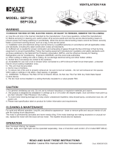
50
60
80
70
10
5
60
15
40
20 30
50
%HUMIDITY MINUTES
% HUMIDITY ADJUSTMENT
%HUMIDITY has been factory set at 80% for most
shower applications. If fan is not responding to changing
humidity conditions, adjust toward 50%. If fan is
responding too often to changing humidity conditions,
adjust toward 80%. If fan is still responding too often at
80%, contact Broan Technical Support.
To adjust the %HUMIDITY:
1. Turn power off at electrical service panel.
2. Use a small screwdriver to carefully rotate
%HUMIDITY control to desired level.
3. Turn power on.
4. Repeat above steps if necessary.
MINUTES ADJUSTMENT (TIMER)
This humidity-sensing fan has a timer that controls how
long the fan remains on after (a) rise in humidity and
(b) humidity level are both below the user-adjustable
%HUMIDITY setting, or after being energized by cycling
power switch.
To adjust the timer:
1. Disconnect power at electrical service panel.
2. Use a small screwdriver to carefully rotate MINUTES
control to increase or decrease time.
3. Turn power on.
4. Repeat above steps if necessary.
Factory settings shown.
SENSOR CLEANING
The humidity sensor is mounted in the control housing. The
sensor will operate most reliably when cleaned occasionally
as follows:
1. Disconnect power at service entrance.
2. Remove the grille. Use a dry dustcloth, clean toothbrush,
or lightly vacuum to clean sensor and grille. DO NOT
USE ABRASIVE CLOTH, STEEL WOOL PADS, OR
SCOURING POWDERS.
3. DO NOT USE cleaning sprays, solvents, or water on or
near the sensor!

INSTALLATION AND USE & CARE INSTRUCTIONS
INSTALLATION
4
OPTION -
To mount housing anywhere between ceiling framing:
Use optional Hanger Bar Kit (sold separately from local distributors or
website). Follow mounting instructions included with kit.
1. Remove blower and all packing
material from fan housing.
2. Remove wiring panel from
fan housing.
ROOF CAP
*
(with built-in damper)
WALL CAP
*
(with built-in
damper)
4-IN. ROUND
ELBOWS
*
FAN
HOUSING
Seal gaps
around
housing.
Seal duct joints
with tape.
INSULATION
(Place around and
over fan housing.)
POWER
CABLE
*
*
Purchase separately.
OR
Keep duct
runs short.
4-IN. ROUND
DUCT
*
ALL INSTALLATIONS
Start here.
IMPORTANT - The ducting from this fan to the outside
of the building has a strong effect on the air flow, noise and
energy use of the fan. Use the shortest, straightest duct routing
possible for best performance, and avoid installing the fan with
smaller ducts than recommended. Insulation around the ducts
can reduce energy loss and inhibit mold growth. Fans installed
with existing ducts may not achieve their rated airflow.
Cooking
Equipment
Floor
COOKING AREA
Do not install above or
inside this area.
45
o
45
o
NOT FOR USE IN
A COOKING AREA.
4. Attach grille brackets to
housing.
3. A pair of flanges may be
attached to housing if
desired or required.
Snap both flange pieces under rolled-over edge
of housing (all four sides).

INSTALLATION AND USE & CARE INSTRUCTIONS
INSTALLATION
5
7. Connect 4-in. round duct.
8. Connect wiring.
Connect power cable to housing with appropriate
UL approved connector. Make wiring connections as
shown in “Wiring Diagrams” section. Re-install wiring
panel and secure with screw from parts bag.
5. Attach damper/duct connector
to fan housing.
Push connector through opening from inside of housing.
Engage tabs and secure with screw from parts bag.
6. Mount housing to ceiling
structure.
Make sure bottom of housing will be flush with finished
ceiling.
For proper location using ½” ceiling material: Bend out
housing tabs to fit against bottom of structure.
Secure housing through mounting ears with
appropriate fasteners.
If mounting housing to I-joist, use wood blocking as
shown.
NEW CONSTRUCTION
For Retrofit Installation - Skip to Page 6.
TABS
HOUSING TABS
I-JOIST
WOOD
BLOCKING
CAUTION
• DO NOT TOUCH THE HUMIDITY-
SENSING CIRCUIT BOARD.
Electrostatic discharge may damage
the circuit board.

INSTALLATION AND USE & CARE INSTRUCTIONS
INSTALLATION
6
10. Finish ceiling, then install grille.
Attach MOUNTING PLATE to housing with (2) SCREWS.
Connect LIGHT PANEL PLUG to receptacle in corner of housing.
Place LIGHT PANEL SLOT over HOOK on MOUNTING PLATE.
Swing opposite side of LIGHT PANEL up to MOUNTING PLATE and
secure with ATTACHMENT SCREW.
Line up GRILLE FRAME with (3) LIGHT PANEL OPENINGS and
rotate GRILLE FRAME clockwise to secure it to LIGHT PANEL.
9. Install blower.
Re-install blower. Secure blower with 2 screws from parts bag and plug
blower into black receptacle.
5. Remove old fan.
Enlarge ceiling opening (if necessary)
to 9¾” parallel to joist) by 10½”
(perpendicular to joist). Leave ductwork
and wiring in place.
6. Fold mounting ears flat
against housing.
RETROFIT
2
10½-in.
9¾-in.
JOIST
1
MOUNTING
PLATE
LIGHT
PANEL
GRILLE
FRAME
ATTACHMENT
SCREW
MOUNTING
PLATE
ATTACHMENT
SCREW (2)
LIGHT PANEL
PLUG
HOOK
SLOT
LIGHT
PANEL
OPENING (3)
CAUTION
• Make sure that the wiring inside of the housing
does not interfere with re-installation of the blower.

INSTALLATION AND USE & CARE INSTRUCTIONS
INSTALLATION
7
7. Connect wiring.
Connect power cable to housing with appropriate UL
approved connector. Make wiring connections as shown
in “Wiring Diagrams” section. Re-install wiring panel and
secure with screw from parts bag.
9. Connect 4-in. round duct.
Pull existing ducting through housing discharge
opening.
Attach and tape ducting to duct connector.
Push connector/ducting back through opening.
Engage tabs and secure with screw from parts
bag.
Install blower. Finish ceiling, then
install grille.
See Steps 9 & 10 on Page 6.
8. Mount fan to ceiling structure.
Mount housing to ceiling structure with standard
drywall or wood screws in locations shown.
*
Center hole optional.
1
2
3
4
TABS
CAUTION
• DO NOT TOUCH THE HUMIDITY-
SENSING CIRCUIT BOARD.
Electrostatic discharge may damage
the circuit board.

INSTALLATION AND USE & CARE INSTRUCTIONS
INSTALLATION
8
WIRING DIAGRAMS
WIRING OPTION #1
• When first switch (1) is ON, fan will operate automatically, based on room humidity conditions.
• Turn fan ON immediately for the set timer period (to control odors), by cycling first switch.
• Use second switch (2) to turn light ON/OFF.
• With optional connection shown, fan will always be ON when light is ON.
BLK
HUMIDITY
CONTROL
LIGHT
FAN
GREY
BRN
BLK
RED
BLK
BLK
WHT
WHT
WHTWHT
WHT
GRD
GRD
LIGHT
(ON/OFF)
FAN
(AUTO/OFF)
120
VAC
LINE
IN
COM
2-FUNCTION CONTROL
(PURCHASE SEPARATELY)
WHT
GRD
SWITCH UNIT
(Optional)
(1)
(2)
WIRING OPTION #2
• When first switch (1) is ON, fan will operate automatically based on room humidity conditions.
• Turn fan ON immediately (to control odors) by using second switch (2).
• Use third switch (3) to turn light ON/OFF.
3-FUNCTION CONTROL
(PURCHASE SEPARATELY)
LIGHT
(ON/OFF)
COM
FAN
(ON/OFF)
FAN AUTO
(AUTO/OFF)
120
VAC
LINE
IN
SWITCH
WHT
GRD
BLK
BLK
WHT
UNIT
BLK
WHT
GRD
BLK
RED
LIGHT
WHT
WHT
BLK
WHT
BRN
HUMIDITY
CONTROL
FAN
WHT
(1)
(2)
(3)
GREY
/